Note: Descriptions are shown in the official language in which they were submitted.
CA 02647842 2008-12-23
HINGING INTERCONNECTOR FOR A CLAMSHELL HANDHELD
ELECTRONIC COMMUNICATION DEVICE
FIELD
This disclosure, in a broad sense, is directed toward a clamshell handheld
communication device that has wireless communication capabilities and the
networks
within which the wireless communication device operates. The present
disclosure further
relates to a hinging interconnector for connecting a first housing to a second
housing.
BACKGROUND
With the proliferation of wireless communication systems, compatible handheld
communication devices are becoming more prevalent, as well as advanced.
Whereas in
the past such handheld communication devices were typically limited to either
voice
transmission (cell phones) or text transmission (pagers and PDAs), today's
consumer often
demands a multifunctional device capable of performing both types of
transmissions,
including even sending and receiving e-mail. Furthermore, these higher-
performance
devices can also be capable of sending and receiving other types of data
including that
which allows the viewing and use of Internet websites. These higher level
functionalities
necessarily require greater user interaction with the devices through included
user
interfaces (Uls) which may have originally been designed to accommodate making
and
receiving telephone calls and sending messages over a related Short Messaging
Service
(SMS). As might be expected, suppliers of such mobile communication devices
and the
related service providers are anxious to meet these customer requirements, but
the
demands of these more advanced functionalities have in many circumstances
rendered the
traditional user interfaces unsatisfactory, a situation that has caused
designers to have to
improve the Uls through which users input information and control these
sophisticated
operations.
Keyboards are used on many handheld devices, including telephones and mobile
communication devices. The size of keyboards has been reduced over the years,
as newer,
smaller devices have become popular. Cell phones, for example, are now sized
to fit in
one's pocket or the palm of the hand. As the size of the devices has
decreased, the more
important it has become to utilize the entire keyboard surface as efficiently
as possible.
1
CA 02647842 2008-12-23
Many keyboards on mobile devices have an input device for navigation through
the graphical user interface. These interfaces include such devices as
trackballs and
rotating wheels which can be used to effect movement of a cursor or pointer,
or to scroll
up, down and about a displayed page. These navigation devices often occupy a
relatively
large amount of space on the incorporating mobile device. Because the
navigation device
is frequently used and often requires fine control, a lower end size
limitation will normally
be observed by device designers. To accommodate such larger, more convenient
navigation devices on the housing of the mobile device, the amount of space
that is
available for the keys of the keyboard is correspondingly reduced if the
keyboard and
navigation device are proximately located to one another.
BRIEF DESCRIPTION OF THE DRAWINGS
Examplary methods and arrangements conducted and configured according to the
advantageous solutions presented herein are depicted in the accompanying
drawings
wherein:
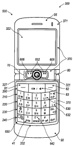
FIG. 1 illustrates a clamshell handheld wireless communication device with a
trackball assembly, configured according to the present teachings, in an open
configuration with a reduced keyboard and a hinging interconnector;
FIG. 2 is a block diagram representing a wireless handheld communication
device
interacting in a communication network;
FIG. 3A illustrates an examplary QWERTY keyboard layout;
FIG. 3B illustrates an examplary QWERTZ keyboard layout;
FIG. 3C illustrates an examplary AZERTY keyboard layout;
FIG. 3D illustrates an examplary Dvorak keyboard layout;
FIG. 4 illustrates a QWERTY keyboard layout paired with a traditional ten-key
keyboard;
FIG. 5 illustrates ten digits comprising the numerals 0-9 arranged in a
traditional,
ITU Standard E.161 numeric telephone keypad layout, including the * and # keys
flanking
the 0 key;
FIG. 6 illustrates a traditional or standard phone key arrangement or layout
according to the ITU Standard E. 161 including both numerals and letters;
2
CA 02647842 2008-12-23
FIG. 7 illustrates a front perspective view of a clamshell handheld wireless
communication device, according to the present teachings, in an open
configuration with a
full keyboard and hinging interconnector;
FIG. 8 illustrates a left side view of a clamshell handheld wireless
communication
device;
FIG. 9 illustrates a rear perspective view of a clamshell handheld wireless
communication device;
FIG. 10 illustrates a front perspective view of a clamshell handheld wireless
communication device in a closed configuration.
FIG. 11 illustrates a clamshell handheld wireless communication device with a
roller-barrel, configured according to the present teachings, in an open
configuration with
a reduced keyboard and a hinging interconnector; and
FIG. 12 illustrates a clamshell handheld wireless communication device with a
four-way keypad, configured according to the present teachings, in an open
configuration
with a reduced keyboard and a hinging interconnector
DETAILED DESCRIPTION
An examplary handheld wireless communication device 300 is shown in FIG. 1,
and the device's cooperation in a wireless network 319 is exemplified in the
block
diagram of FIG. 2. These figures are examplary only, and those persons skilled
in the art
will appreciate the additional elements and modifications necessary to make
the device
300 work in particular network environments.
As shown in the block diagram of FIG. 2, the handheld device 300 includes a
microprocessor 338 that controls the operation of the device 300. A
communication
subsystem 311 performs all communication transmission and reception with the
wireless
network 319. The microprocessor 338 further connects with an auxiliary
input/output
(I/O) subsystem 328, a serial port (preferably a Universal Serial Bus port)
330, a display
322, a keyboard 332, a speaker 334, a microphone 336, random access memory
(RAM)
326, and flash memory 324. Other communication subsystems 340 and other device
subsystems 342 are generally indicated as being functionally connected with
the
microprocessor 338 as well. An example of a communication subsystem 340 is
that of a
short range communication system such as BLUETOOTH communication module or a
Wi-Fi communication module (a communication module in compliance with IEEE
3
CA 02647842 2008-12-23
802.1 lb) and associated circuits and components. Additionally, the
microprocessor 338 is
able to perform operating system functions and preferably enables execution of
software
applications on the handheld wireless communication device 300.
The auxiliary I/O subsystem 328 can take the form of a variety of different
navigation tools (multi-directional or single-directional) such as a
navigation too1327 with
trackball 321 as illustrated in the examplary embodiment shown in FIG. 1, or a
thumbwheel, a navigation pad, a joystick, or the like. These navigation tools
are
preferably located on the front surface of the handheld device 300 when in an
open
configuration 500 but may be located on any exterior surface of the handheld
device 300.
Other auxiliary I/O subsystems can include external display devices and
externally
connected keyboards (not shown). While the above examples have been provided
in
relation to the auxiliary I/O subsystem 328, other subsystems capable of
providing input or
receiving output from the handheld device 300 are considered within the scope
of this
disclosure. Additionally, other keys may be placed along the side of the
handheld device
300 to function as escape keys, volume control keys 100, scrolling keys, power
switches,
or user programmable keys (105, 120), and may likewise be programmed
accordingly.
As may be appreciated from FIG. 1, the handheld wireless communication device
300 comprises a lighted display 322 located above a keyboard 332 constituting
a user
input and suitable for accommodating textual input to the handheld wireless
communication device 300. When the device is in the open configuration 500,
the front
face 370 has a navigation row 70 and a keypad 650 that includes alphanumeric
keys 630,
alphabetic keys 632, numeric keys 642, and other function keys 41 as shown in
FIG. 1.
Keys, typically of a push-button or push-pad nature, perform well as data
entry
devices but present problems to the user when they must also be used to effect
navigational control over a screen-cursor. In order to solve this problem the
present
handheld wireless communication device 300 preferably includes an auxiliary
input that
acts as a cursor navigation tool 327 and which is also located upon the front
face 370 of
the device 300 in the open configuration 500. While in the open configuration
500, the
front face location 370 of the navigation tool 327 accommodates thumb-
actuation similar
to the keys of the keyboard 332. A particularly usable embodiment provides the
navigation tool 327 in the form of a trackball 321 which is easily utilized to
instruct two-
dimensional screen cursor movement in substantially any direction, as well as
act as an
actuator when the trackba11321 is depressed like a button. The placement of
the navigation
4
CA 02647842 2008-12-23
tool 327 is preferably above the keyboard 332 and below the display screen
322; here, it
avoids interference during keyboarding and does not block the user's view of
the display
screen 322 during use. (See FIG. 1).
As illustrated in FIG. 1, the present disclosure is directed to a clamshell
handheld
wireless communication device 300 configured to send and receive text
messages. The
handheld device 300 includes a hand cradleable body 371 configured to be held
in one
hand by an operator of the device during text entry. A display 322 is included
that is
located on a front face 370 of the body 371 in the open configuration 500 and
upon which
information is displayed to the operator during text entry. A keypad 650 is
also located on
the front face 370 of the body 371 in the open configuration 500 and includes
a plurality of
keys. A navigation row 70 including menu keys 652 and a navigation tool 327 is
also
located on the front face 370 of the body 371 in the open configuration 500.
The
alphanumeric input keys 630 comprise a plurality of alphabetic and/or numeric
keys (632,
642) having letters and/or numbers associated therewith. The order of the
letters of the
alphabetic keys 632 on the presently disclosed handheld device 300 can be
described as
being of a traditional, but non-ITU Standard E. 161 layout. This terminology
has been
utilized to delineate the fact that such a telephone keypad as depicted in
FIG. 6 may not
allow for efficient text entry on the handheld device 300.
The clamshell handheld wireless communication device 300 is also configured to
send and receive voice communications such as mobile telephone calls. To
facilitate
telephone calls, two call keys or outer keys (not shown) are provided in the
navigation row
70 (so-called because it includes the navigation tool 327) at the outer ends
of the
navigation row 70. One of the two call keys is a call initiation key, and the
other is a call
termination key. The navigation row 70 also includes another pair of keys
("flanking
keys" 606, 608) that are located immediately adjacent to the navigation tool
327, with one
flanking key on either side of the navigation tool 327. It is noted that the
outer keys are
referred to as such not because they are necessarily the outermost keys in the
navigation
row - there may be additional keys located even further outwardly of the outer
keys if
desired - but rather because they are located outwardly with respect to the
flanking keys
(606, 608). The flanking keys (606, 608) may, for instance, constitute the
menu keys 652,
which include a menu call-up key 606 and an escape or back key 608. The menu
call-up
key 606 is used to bring up a menu on the display screen 322 and the escape
key 608 is
used to return to the previous screen or previous menu selection. The
functions of the call
CA 02647842 2008-12-23
keys and the menu keys may, of course, be provided by buttons that are located
elsewhere
on the handheld device 300, with different functions assigned to the outer
keys and the
flanking keys (606, 608).
Furthermore, the handheld device 300 is equipped with components to enable
operation of various programs, as shown in FIG. 2. In an examplary embodiment,
the
flash memory 324 is enabled to provide a storage location for the operating
system 357,
device programs 358, and data. The operating system 357 is generally
configured to
manage other application programs 358 that are also stored in memory 324 and
executable
on the processor 338. The operating system 357 honors requests for services
made by
application programs 358 through predefined application program 358
interfaces. More
specifically, the operating system 357 typically determines the order in which
multiple
applications 358 are executed on the processor 338 and the execution time
allotted for
each application 358, manages the sharing of memory 324 among multiple
applications
358, handles input and output to and from other device subsystems 342, and so
on. In
addition, users can typically interact directly with the operating system 357
through a user
interface, which can include the keyboard 332 and display screen 322. While in
an
examplary embodiment the operating system 357 is stored in flash memory 324,
the
operating system 357 in other embodiments is stored in read-only memory (ROM)
or
similar storage element (not shown). As those skilled in the art will
appreciate, the
operating system 357, device application 358 or parts thereof may be loaded in
RAM 326
or other volatile memory.
In one examplary embodiment, the flash memory 324 contains
programs/applications 358 for execution on the handheld device 300 including
an address
book 352, a personal information manager (PIM) 354, and the device state 350.
Furthermore, programs 358 and other information 356 including data can be
segregated
upon storage in the flash memory 324 of the handheld device 300.
When the handheld device 300 is enabled for two-way communication within the
wireless communication network 319, it can send and receive signals from a
mobile
communication service. Examples of communication systems enabled for two-way
communication include, but are not limited to, the General Packet Radio
Service (GPRS)
network, the Universal Mobile Telecommunication Service (UMTS) network, the
Enhanced Data for Global Evolution (EDGE) network, and the Code Division
Multiple
Access (CDMA) network and those networks, generally described as packet-
switched,
6
CA 02647842 2008-12-23
narrowband, data-only technologies which are mainly used for short burst
wireless data
transfer. For the systems listed above, the handheld wireless communication
device 300
must be properly enabled to transmit and receive signals from the
communication network
319. Other systems may not require such identifying information. GPRS, UMTS,
and
EDGE require the use of a Subscriber Identity Module (SIM) in order to allow
communication with the communication network 319. Likewise, most CDMA systems
require the use of a Removable Identity Module (RUIM) in order to communicate
with the
CDMA network. The RUIM and SIM card can be used in multiple different
communication devices 300. The handheld communication device 300 may be able
to
operate some features without a SIM/RUIM card, but it will not be able to
communicate
with the network 319. A SIMIRUIM interface 344 located within the device 300
allows
for removal or insertion of a SIM/RUIM card (not shown). The SIM/RUIM card
features
memory and holds key configurations 351, and other information 353 such as
identification and subscriber related information. With a properly enabled
communication
device 300, two-way communication between the handheld wireless communication
device 300 and communication network 319 is possible.
If the handheld wireless communication device 300 is enabled as described
above
or the communication network 319 does not require such enablement, the two-way
communication enabled handheld device 300 is able to both transmit and receive
information from the communication network 319. The transfer of communication
can be
from the handheld device 300 or to the device 300. In order to communicate
with the
communication network 319, the handheld device 300 in the presently described
examplary embodiment is equipped with an integral or internal antenna 318 for
transmitting signals to the communication network 319. Likewise the handheld
wireless
communication device 300 in the presently described examplary embodiment is
equipped
with another antenna 316 for receiving communication from the communication
network
319. These antennae (316, 318) in another examplary embodiment are combined
into a
single antenna (not shown). As one skilled in the art would appreciate, the
antenna or
antennae (316, 318) in another embodiment are externally mounted on the
handheld
device 300.
When equipped for two-way communication, the handheld wireless
communication device 300 features a communication subsystem 311. As is well
known in
the art, this communication subsystem 311 is modified so that it can support
the
7
CA 02647842 2008-12-23
operational needs of the handheld device 300. The subsystem 311 includes a
transmitter
314 and receiver 312 including the associated antenna or antennae (316, 318)
as described
above, local oscillators (LOs) 313, and a processing module 320 which in the
presently
described examplary embodiment is a digital signal processor (DSP) 320.
It is contemplated that communication by the handheld device 300 with the
wireless network 319 can be any type of communication that both the wireless
network
319 and handheld device 300 are enabled to transmit, receive and process. In
general,
these can be classified as voice and data. Voice communication is
communication in
which signals for audible sounds are transmitted by the handheld device 300
through the
communication network 319. Data is all other types of communication that the
handheld
device 300 is capable of performing within the constraints of the wireless
network 319.
Example device applications that can depend on such data include email,
contacts
and calendars. For each such application synchronization with home-based
versions on
the applications can be critical for either or both of their long term and
short term utility.
As an example, emails are often time sensitive, so substantially real time
synchronization
is highly desirable. Contacts, on the other hand, can be usually updated less
frequently
without inconvenience. Therefore, the utility of the handheld device 300 is
significantly
enhanced when connectable within a communication system, and particularly when
connectable on a wireless basis in a network 319 in which voice, text
messaging, and other
data transfer are accommodated.
As intimated hereinabove, one of the more important aspects of the handheld
wireless communication device 300 to which this disclosure is directed is its
size. While
some users will grasp the handheld device 300 in both hands, it is intended
that a
predominance of users will cradle the handheld device 300 in one hand in such
a manner
that input and control over the handheld device 300 can be effected using the
thumb of the
same hand in which the handheld device 300 is held. However, it is appreciated
that
additional control can be effected by using both hands. As a handheld device
300 that is
easy to grasp and desirably pocketable, the size of the handheld device 300
must be kept
commensurately small. Of the device's dimensions, limiting its width is
important for the
purpose of assuring cradleability in a user's hand. Moreover, it is preferred
that the width
of the handheld device 300 be maintained at less than eight centimeters
(approximately
three inches). Keeping the handheld device 300 within these dimensional limits
provides
a hand cradleable unit that users prefer for its usability and portability.
Limitations with
8
CA 02647842 2008-12-23
respect to the height (length) of the handheld device 300 are less stringent
when
considering hand-cradleability. Therefore, in order to gain greater size, the
handheld
device 300 can be elongated so that its height is greater than its width, but
still remains
easily supported and operated in one hand.
A potential drawback is presented by the small size of the handheld device 300
in
that there is limited exterior surface area for the inclusion of user input
and device output
features. This is especially true for the "prime real estate" on the front
face 370 of the
handheld device 300 in the open configuration 500, where it is most
advantageous to
include a display screen 322 that outputs information to the user. The display
screen 322
is preferably located above a keyboard 332 that is utilized for data entry
into the handheld
device 300 by the user. If the screen 322 is provided below the keyboard 332,
a problem
occurs in that viewing the screen 322 is inhibited when the user is inputting
data using the
keyboard 332. Therefore it is preferred that the display screen 322 be above
the input
area, thereby solving the problem by assuring that the hands and fingers do
not block the
view of the screen 322 during data entry periods.
To facilitate textual data entry into the handheld device 300, an alphabetic
keyboard 332 is provided. In the examplary illustrated embodiment, a full
alphabetic
keyboard 332 is utilized in which there is one key per letter (with some of
the letter keys
also having numbers, symbols, or functions associated with them). In this
regard, the
associated letters can be organized in QWERTY, QWERTZ, AZERTY, or Dvorak
layout,
among others, thereby capitalizing on certain users' familiarity with these
various letter
orders. In order to stay within the bounds of the limited front surface area,
however, each
of the keys must be commensurately small when, for example, twenty-six keys
must be
provided in the instance of the English language.
FIG. 1 illustrates an embodiment of the clamshell handheld wireless
communication device 300 in an open configuration 500. The handheld device 300
is
provided with a keyboard 332 to enter text data and place telephone calls and
a display
screen 322 for communicating information to the user. A connect/send key (not
shown) is
preferably provided to aid in the placement of a phone call. Additionally, a
disconnect/end key (not shown) is preferably provided. The send key and end
key
preferably are arranged in the navigation row 70 including the navigation tool
327.
Additionally, the navigation row 70 preferably has a menu call-up key 606 and
a back key
or escape key 608.
9
CA 02647842 2008-12-23
The keyboard 332 includes a plurality of keys that can be of a physical nature
such
as actuable buttons, or they can be of a software nature, typically
constituted by virtual
representations of physical keys on a display screen 322 (referred to herein
as "virtual
keys"). It is also contemplated that the user input can be provided as a
combination of the
two types of keys. Each key of the plurality of keys has at least one actuable
action which
can be the input of a character, a command or a function. In this context,
"characters" are
contemplated to exemplarily include alphabetic letters, language symbols,
numbers,
punctuation, insignias, icons, pictures, and even a blank space. Input
commands and
functions can include such things as delete, backspace, moving a cursor up,
down, left or
right, initiating an arithmetic function or command, initiating a command or
function
specific to an application program or feature in use, initiating a command or
function
programmed by the user and other such commands and functions that are well
known to
those persons skilled in the art. Specific keys or other types of input
devices can be used
to navigate through the various applications and features thereof. Further,
depending on
the application 358 or feature in use, specific keys can be enabled or
disabled.
In the case of physical keys, all or a portion of the plurality of keys have
one or
more indicia representing character(s), command(s), and/or functions(s)
displayed at their
top surface and/or on the surface of the area adjacent the respective key. In
the instance
where the indicia of a key's function is provided adjacent the key, the
indicia can be
printed on the device cover beside the key, or in the instance of keys located
adjacent the
display screen 322. Additionally, current indicia for the key may be
temporarily shown
nearby the key on the display screen 322.
In the case of virtual keys, the indicia for the respective keys are shown on
the
display screen 322, which in one embodiment is enabled by touching the display
screen
322, for example, with a stylus to generate the character or activate the
indicated
command or function. Some examples of display screens 322 capable of detecting
a touch
include resistive, capacitive, projected capacitive, infrared and surface
acoustic wave
(SAW) touchscreens.
Physical and virtual keys can be combined in many different ways as
appreciated
by those skilled in the art. In one embodiment, physical and virtual keys are
combined
such that the plurality of enabled keys for a particular application or
feature of the
handheld wireless communication device 300 is shown on the display screen 322
in the
same configuration as the physical keys. Using this configuration, the user
can select the
CA 02647842 2008-12-23
appropriate physical key corresponding to what is shown on the display screen
322. Thus,
the desired character, command or function is obtained by depressing the
physical key
corresponding to the character, command or function displayed at a
corresponding
position on the display screen 322, rather than touching the display screen
322.
The various characters, commands, and functions associated with keyboard
typing
in general are traditionally arranged using various conventions. The most
common of
these in the United States, for instance, is the QWERTY keyboard layout.
Others include
the QWERTZ, AZERTY, and Dvorak keyboard configurations. The QWERTY keyboard
layout is the standard English-language alphabetic key arrangement 44a shown
in FIG.
3A. The QWERTZ keyboard layout is normally used in German-speaking regions;
this
alphabetic key arrangement 44b is shown in FIG. 3B. The AZERTY keyboard layout
44c
is normally used in French-speaking regions and is shown in FIG. 3C. The
Dvorak
keyboard layout was designed to allow typists to type faster; this alphabetic
key
arrangement 44d is shown in FIG. 3D. In other examplary embodiments, keyboards
having multi-language key arrangements can be implemented.
Alphabetic key arrangements are often presented along with numeric key
arrangements. Typically, the numbers 1-9 and 0 are positioned in the row above
the
alphabetic keys 44a-d, as shown in FIG. 3A-D. Alternatively, the numbers share
keys
with the alphabetic characters, such as the top row of the QWERTY keyboard.
Yet
another examplary numeric key arrangement is shown in FIG. 4, where a "ten-
key" style
numeric keypad 46 is provided on a separate set of keys that is spaced from
the
alphabetic/numeric key arrangement 44. Still further, ten-key numeric
arrangements may
be common with or shared with a subset of the alphabetic keys, as best shown
in FIGS. 9
and 10. The ten-key styled numeric keypad 46 includes the numbers "7", "8",
"9"
arranged in a top row, "4", "5", "6" arranged in a second row, "1 ", "2", "3"
arranged in a
third row, and "0" in a bottom row. Further, a numeric phone key arrangement
42 is
exemplarily illustrated in FIG. 5.
As shown in FIG. 5, the numeric phone key arrangement 42 may also utilize a
surface treatment on the surface of the center "5" key. This surface treatment
is
configured such that the top surface of the key is distinctive from the
surface of other keys.
Preferably the surface treatment is in the form of a raised bump or recessed
dimple 43.
Alternatively, raised bumps may be positioned on the housing around the "5"
key and do
not necessarily have to be positioned directly on the key.
11
CA 02647842 2008-12-23
It is desirable for handheld devices 300 to include a combined text-entry
keyboard
and a telephony keyboard. Examples of such handheld devices 300 include mobile
stations, cellular telephones, wireless personal digital assistants (PDAs),
two-way paging
devices, and others. Various keyboards are used with such devices and can be
termed a
full keyboard, a reduced-format keyboard, or phone key pad. In embodiments of
a
handheld device 300 having a full keyboard, the alphabetic characters are
singly
associated with the plurality of physical keys. Thus, in an English-language
keyboard of
this configuration, there are at least 26 keys in the plurality, with one
letter per alphabetic
key.
FIGS. 5 and 6 both feature numeric keys arranged according to the ITU Standard
E.161 form. In addition, FIG. 6 also incorporates alphabetic characters
according to the
ITU Standard E.161 layout as well.
Reference is now made to FIG. 7, which discloses an examplary embodiment
having a full alphabetic keyboard arrangement. In particular, as shown in FIG.
7, only one
letter of the alphabet is associated with any given alphabetic key within the
keys of the
keypad 650. This is in contrast to reduced-format arrangements (as shown in
FIG. 1), in
which multiple letters of the alphabet may be associated with at least some of
the
alphabetic keys of a keyboard 332. Additionally, as alluded to above and shown
in the
referenced figures, some of the alphabetic keys also have numbers, symbols, or
functions
associated with them. In the specifically illustrated embodiment, the
alphabetic keys
(including those also having numbers, symbols, or functions associated with
them) are
arranged in a QWERTY arrangement, although any of the other full-keyboard
arrangements (QWERTZ, AZERTY, or Dvorak) may also be implemented within the
scope of this disclosure.
As described above, the International Telecommunications Union ("ITU") has
established phone standards for the arrangement of alphanumeric keys. The
standard
phone numeric key arrangement shown in FIGS. 5 (no alphabetic letters) and 6
(with
alphabetic letters) corresponds to ITU Standard E.161, entitled "Arrangement
of Digits,
Letters, and Symbols on Telephones and Other Devices That Can Be Used for
Gaining
Access to a Telephone Network." This standard is also known as ANSI TI.703-
1995/1999
and ISO/IEC 9995-8:1994. As shown in FIG. 1, the numeric key arrangement can
be
overlaid on a QWERTY arrangement. The numeric arrangement as shown can be
aptly
described as a top-to-bottom ascending order three-by-three-over-zero pattern.
12
CA 02647842 2008-12-23
While several keyboard layouts have been described above, the layouts can be
described as having keys disposed on the keyboard in a QWERTY, reduced QWERTY,
QWERTZ, Dvorak, or AZERTY key layout. These familiar keyboard layouts allow
users
to type more intuitively and quickly than, for example, on the standard
alphabetic layout
on a telephone pad. As mentioned above, the key arrangements can be reduced
compared
to a standard layout through the use of more than one letter or character per
key. By
utilizing fewer keys, the keys can be made larger and therefore more
convenient to the
user.
In at least one embodiment, a handheld wireless communication device 300 that
is
configured to send and receive email text messages comprises a hand cradleable
body 371
configured to be held in a text entry orientation by an operator or user. (For
example see
FIGS. 1 and 7). When the body 371 of the handheld wireless communication
device 300
is in the open configuration, it has a front face 370 at which a display
screen 322 is located
and upon which information is displayed to the operator of the handheld device
300 in the
text entry orientation. The handheld device 300 further comprises a
microprocessor
configured to run software programs on the handheld device 300 and to receive
operator
commands from user inputs, such as a keyboard 332 and trackball navigation
tool 321,
located on the handheld device 300. The keyboard as shown in FIG. 1 includes a
plurality
of input keys which can be associated with alphabetic, numeric, or command
values. As
shown in FIG. 1, the handheld wireless device 300 can include a keypad 650
that is
located below the display screen 322 at the front face 370 of the body 371
(when in the
open configuration 500) and the keypad 650 comprises a plurality of keys of
which a
portion are alphanumeric input keys 630. These alphanumeric input keys 630
comprise
alphabetic keys 632 which have letters arranged in one of the above described
arrangements including but not limited to QWERTY, QWERTZ, AZERTY, and Dvorak
arrangements. Furthermore, the arrangement can be of a full arrangement or
reduced
arrangement as described above, wherein the reduced arrangement has more than
one
letter associated with at least one key. As shown in FIG. 7, a full QWERTY
arrangement
is provided on keyboard 332 along with additional numeric, symbol and function
keys. A
reduced QWERTY arrangement is presented in FIG. 1. Additionally, a navigation
tool
327 can be located between the display 322 and the keypad 650 in the text
entry
orientation.
13
CA 02647842 2008-12-23
As described above, it is desirable to provide a handheld electronic
communication
device 300 with a navigation input device 327. A clamshell handheld
communication
device 300 according to the present teachings consists of three pieces, a
first housing 90
and a second housing 95, which are pivotally coupled one to the other at a
hinging
interconnector 80. Additionally, a keypad 650 can be located on the first
housing 90 and
the display screen 322 can be located on the second housing 95. Furthermore,
the
trackball assembly can be mounted on the hinging interconnector 80. In other
embodiments, the navigation input device 327 need not be limited to a
trackball assembly
- a roller-barrel 331 (see FIG. 11), four-way keypad 341 (see FIG. 12), or
other types of
navigation input devices are encompassed within the scope of this disclosure.
A clamshell device is capable of transitioning between an open configuration
500
and closed configuration 600 as illustrated in FIGS. 1 and 10, respectively.
In the closed
configuration 600, the second housing 95 substantially covers the keypad 650
on the first
housing 90. Additionally, when the clamshell handheld electronic communication
device
300 is in a closed configuration 600, the trackball 321 is concealed between
the first
housing 90 and second housing 95. While in the illustrated embodiments the
keypad 650 is
concealed by the second housing 95, other embodiments of the second housing
according
to the present teachings may only conceal a portion of the keypad 650 on the
first housing
90. In at least one embodiment the keypad 650 covers a substantial entirety of
an interiorly
exposed surface of the first housing 90. Additionally, in another embodiment
the display
screen 322 covers a substantial entirety of an interiorly exposed surface of
the second
housing 95 relative the closed configuration 600. In yet another embodiment,
the keypad
650 covers a substantial entirety of an interiorly exposed surface of the
first housing 90,
and the display screen 322 covers a substantial entirety of an interiorly
exposed surface of
the second housing 95
The keypad 650 of the first housing 90 can have a variety of different keys
each
associated with at least one of an alphabetic letter, a numeral, a command and
a function.
As illustrated in FIG. 1, the first row 200 can include three keys - a left
menu selection
key 81, a right menu selection keys 82, and a camera" key 83 in the center.
The left menu
key and right menu key 82 can be used to input a respective function shown on
the bottom
left and right portions of the display screen 322. For example, in one
embodiment, when
the clamshell device 300 is in the open configuration 500, the "message"
function may be
listed on the bottom left of the display screen 322 and the "contacts"
function may be
14
CA 02647842 2008-12-23
listed on the bottom right of the display screen 332. The "message" function
is associated
with a program that allows a user to enter a messaging application that is
capable of
creating, sending or editing messages which can include at least one of SMS,
MMS, and
email. Similarly, the "contacts" function presents a user a listing of names
and addresses.
According to the present teachings, the user would input the left general menu
key 81 to
select the "message" function. Likewise, the user would input the right
general menu key
82 to select the "contacts" function. In a similar manner, other user
selectable functions
that appear in the bottom left and right portions of the screen can be
selected by the user as
described above. In addition, while the general menu selection keys (81, 82)
have been
described as activating functions shown on the bottom left and right portions
of the display
screen 322, the functions need not be limited to those particular positions.
The center key
83 in the first row 200 is a camera key which allows a user to activate the
camera option
when using the telephone functionality on the device 300. Other functions
known to one
skilled in the art may be likewise programmed into the first row 200.
Analogously, the
sixth row 250 includes three keys in the current embodiment and these keys can
have
various functions associated therewith as would be known to one skilled in the
art.
In addition, both the first housing 90 and second housing 95 can have an
accommodation space 620 recessed into each housing that receives at least a
portion of the
trackball 321 when the device 300 is in a closed configuration 600. In this
configuration,
the hinging interconnector provides a mounting platform for the trackball 321
and the first
housing 90 and second housing accommodate for a protruding trackball 321 with
the
accommodation space 620 in the respective housing. In other embodiments, the
accommodation space 620 may be provided only on the first housing 90 or only
on the
second housing 95.
Additionally, in one embodiment at least one input key may be mounted adjacent
the trackball 321 on the hinging interconnector 80. In other embodiments as
illustrated by
FIGS. 1 and 7, two input keys, each one flanking the trackball 321 on the
hinging
interconnector 80, may be provided. As discussed previously, the input key
immediately
to the left of the trackball 321 may be a menu key 606 and the input key
immediately to
the right of the trackball may be an escape key 608. In yet another
embodiment,
additional keys may be provided on the hinging interconnector. In one
embodiment, the
hinging interconnector 80 and the first and second housing (90, 95) have
approximately
the same width relative the clamshell handheld electronic communication device
300 in
CA 02647842 2008-12-23
the closed configuration 600. In another embodiment, the hinging
interconnector 80 has a
width approximately one-half the width of either of the first and second
housings (90, 95)
relative the clamshell handheld electronic communication device 300 in the
closed
configuration 600. FIGS. 1. and 7 illustrate embodiments in which the hinging
interconnector 80 is approximately three-fourth the width of either the first
and second
housings (90, 95) relative the clamshell handheld electronic communication
device 300 in
the closed configuration 600. However, hinging interconnectors 80 of various
widths, as
would be recognized by one skilled in the art, are encompassed within the
present
disclosure. A microprocessor 338 can be housed within the device 300 and is
configured
to receive and process input data from the keypad 650 and trackball 321 such
that it
outputs corresponding display instructional data to the display screen 322.
FIG. 8 illustrates a side view of the clamshell handheld wireless device 300
in an
open configuration 500. From this view, two hinges (85, 86) are visible. These
hinges
(85,86) connect the first housing 90, second housing 95 and hinging
interconnector 80. In
one embodiment, only two hinges (85, 86), one which extends through the width
of the
first housing 90 and one which extends through the width of the second housing
95 are
used to hold the housings and hinging interconnector 80 together. However, in
another
embodiment, four hinges are used, two hinges extend at opposite sides through
the second
housing 95 and another two hinges which extend at opposite sides through the
first
housing 90, to hold the first housing 90, second housing 95 and hinging
interconnector 80
together. Additionally, FIG. 8 also illustrates an input for the headphone
110, a USB port
330, and a programmable button 120 on the first housing 90.
FIG. 9 illustrates back perspective view of the clamshell handheld wireless
device
300 in an open configuration 500. Likewise, a front display screen 97 (when
the device
300 is in the closed configuration 600) which can present the time, date,
incoming call
information to the user when the device 300 is in the closed configuration
600. On the
first housing 90, hinges 86 and 88 (not shown) are found. Likewise, a
programmable
button 120, USB port 330, an input for headphones I10 are also shown. In
addition, on
the back of the hinging interconnector 80 are a`mute/hold' button 78 and
a`pause/play'
button 79 for user selection. FIG. 10 illustrates a front perspective view of
the clamshell
handheld wireless device 300 in a closed configuration 600. On the first
housing 90,
another programmable button 105 and a volume control button 100 are
illustrated. On the
second housing 95, the front display screen 97 is shown.
16
CA 02647842 2008-12-23
Examplary embodiments have been described hereinabove regarding both
handheld wireless communication devices 300, as well as the communication
networks
319 within which they operate. Again, it should be appreciated that the focus
of the
present disclosure is upon the hinging interconnector 80, which connects the
first housing
90 and second housing 95 of the clamshell handheld communication device 300.
17