Note: Descriptions are shown in the official language in which they were submitted.
CA 02648088 2008-12-24
4146/2033.79574 PATENT APPLICATION
TOOL WITH REPLACEABLE BLADE
BACKGROUND OF THE INVENTION
The present invention relates generally to hand tools
using blades, and more specifically to wallboard taping knives
and similar tools.
A wallboard taping knife or scraper typically has a
large blade with an elongate working edge attached to a handle.
As is well known in the art, such tools are used for spreading
joint compound over wallboard tape to finish joints of adjacent
wallboard panels. Users typically repeatedly dip the knife blade
into a container of wallboard joint compound known as a mud
pan, and also scrape excess compound from the blade against
an edge of the mud pan. Due to the operator stresses on the
blade from these various repetitive activities, it is preferred to
have the blade well secured to the handle such that there is no
play or independent relative movement between the blade and
handle. A strong connection between the blade and handle
CA 02648088 2008-12-24
increases operational life of the tool and reduces user fatigue.
Thus, one design criteria of such a tool is to reduce independent
movement of the blade relative to the handle. Conventional
drywall tools address this concern by manufacturing the tool such
that the blade is permanently attached to the handle of the tool.
A significant portion of operational wear on taping
knives is incurred on the blade edge or at the point where the
blade meets the handle. As the blade becomes worn, it
becomes more difficult to evenly apply the compound. Since
conventional tools have blades that are permanently attached to
the tool, when the blade becomes worn, the entire tool must be
replaced. Another design criteria of taping knives is maintaining
user comfort during periods of extended use.
Utility knives and other tools with replaceable blades
are known in the art. However, in such tools removing the blade
involves unscrewing and/or opening the tool housing, resulting in
a complicated and time-consuming process.
2
CA 02648088 2008-12-24
BRIEF SUMMARY OF THE INVENTION
The above-listed needs are met or exceeded by the
present tool, which features a releasably attachable blade that is
removable upon depressing an actuator. When the actuator is in
a rest position, a latch is in a latched position and extends
through a latch opening in the blade, thereby securely attaching
the blade to a tool handle. When the actuator is depressed, an
actuator extension on the actuator engages a complementary
latch extension on the latch, causing the latch to retract from a
latched position to a released position such that the latch no
longer extends through the latch opening, thus allowing the blade
to be removed from the tool handle.
More specifically, a tool handle is provided for use
with a removable blade having a latch opening, the tool handle
having a housing defining a blade chamber in the housing, a
latch disposed in the housing, configured for moving between a
latched position and a released position. In the latched position,
the latch is configured to extend through the latch opening. Also
included is an actuator at least partially enclosed within the
housing, configured for moving between a rest position and a
3
CA 02648088 2012-09-12
depressed position, wherein movement of the actuator to the depressed position
causes the
latch to move to the released position.
In a broad aspect, the present invention provides a tool handle for use with a
removable blade having a latch opening, the tool handle comprising: a housing
defining a blade
chamber within said housing; a latch that is one rigid piece and disposed in
said housing, said
latch configured for moving between a latched position and a released
position, in said latched
position, said latch being configured to extend through the latch opening;
said latch further
comprising U-shaped latch shoulders; a latch retainer comprising latch
retainer portions
configured to engage said latch shoulders; a latch biasing device that is
received within a socket
located in the latch; an actuator at least partially enclosed within said
housing, configured for
moving between a rest position and a depressed position, wherein movement of
said actuator to
said depressed position causes said latch to move to said released position;
and said latch and
said actuator have complementary surfaces comprising inclined panes that are
in constant
contact with one another and that are configured to slidingly engage each
other to enable said
latch biasing device to effectively bias said actuator to said rest position
so that progressive
movement of said actuator from said rest position to said depressed position
against said latch
biasing device results in progressive retraction of said latch from said
latched position to said
released position.
In another broad aspect, the present invention provides a removable blade for
use with a tool handle having a housing defining a blade chamber within the
housing, a latch
that is one rigid piece and disposed in the housing, configured for moving
between a latched
position and a released position, a biasing device urging said latch to the
latched position, an
actuator at least partially enclosed within the housing, configured for moving
between a rest
position and a depressed position wherein movement of the actuator to the
depressed position
against a force exerted by said biasing device causes the latch to move to the
released position,
the latch and actuator having complementary surfaces that slidingly engage
each other to move
the latch between the latched position and the released position with
progressive movement of
said actuator, the removable blade comprising: a blade working portion; a
blade shank
associated with said blade working portion; a latch opening in said blade
shank constructed and
arranged for receiving the latch wherein, in the latched position, the latch
extends through said
4
CA 02648088 2012-09-12
latch opening; the latch further comprising U-shaped latch shoulders; a latch
retainer comprising
latch retainer portions configured to engage said latch shoulders; and a latch
biasing device that
is received within a socket located in the latch.
In another broad aspect, the present invention provides a tool, comprising: a
tool
handle having a housing defining a blade chamber within the housing; a latch
that is one rigid
piece and disposed in the housing, configured for moving between a latched
position and a
released position; a biasing device urging the latch to the latched position;
an actuator at least
partially enclosed within the housing, configured for moving between a rest
position and a
depressed position wherein movement of the actuator to the depressed position
against a force
exerted by the biasing device causes the latch to move to the released
position; a removable
blade having a blade working portion; a blade shank associated with said blade
working portion;
and a latch opening in said blade shank constructed and arranged for receiving
said latch
wherein, in said latched position, said latch extends through said latch
opening; wherein the
latch and actuator have complementary surfaces that slidingiy engage each
other to move the
latch between the latched position and the released position with progressive
movement of said
actuator; the latch further comprising U-shaped latch shoulders; a latch
retainer comprising latch
retainer portions configured to engage said latch shoulders; and a latch
biasing device that is
received within a socket located in the latch.
BRIEF DESCRITPION OF THE SEVERAL VIEWS OF THE DRAWINGS
FIG. 1 is an exploded top perspective view of the present tool;
FIG. 2 is a fragmentary perspective view of the tool handle with portions
removed
from clarity;
FIG. 3 is an exploded top perspective view of the tool of FIG. 1 showing
components of the tool handle, with portions removed for clarity;
FIG. 4 is a cross-section taken along the line 4-4 of FIG. 1 and in the
direction
indicated generally; and
FIG. 5 is a cross-section similar to FIG. 4 showing the actuator in a
depressed
position.
4a
CA 02648088 2008-12-24
DETAILED DESCRIPTION OF THE INVENTION
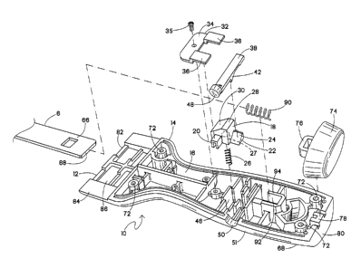
Referring now to FIGs. 1-3, a tool is generally
designated 10 and has a tool handle 12 with a housing 14
defining a blade chamber 16. A latch 18 is disposed in the
housing 14 and is configured and arranged to move between a
latched position (FIG. 4) and a released position (FIG. 5). In the
preferred embodiment, the latch 18 has at least one, but
preferably two latch shoulders 20 extending laterally from the
latch transversely to a longitudinal axis of the tool handle 12.
Also included on the latch 18 is a generally wedge-shaped latch
formation 22 generally extending along the handle longitudinal
axis and having a latch inclined surface 24 forming a plane facing
transverse to the handle longitudinal axis.
A biasing device 26, preferably a spring, is
associated at one end with the latch 18, and at the other end with
the housing 14, such that the latch is urged into the latched
position (FIG. 4). More specifically, the biasing device 26 is
located in and depends from a corresponding socket 27 (shown
hidden in FIG. 3) in the latch 18. The latch 18 also has a lug 28
having a lug inclined surface 30 facing the blade chamber 16.
5
CA 02648088 2008-12-24
A latch retainer 32 having two portions is disposed in
the housing 14. A first retainer portion 34 is mounted, preferably
using a fastener such as a screw 35 (FIG. 3), to the housing 14,
and a second retainer portion 36 is associated with and engages
the two latch shoulders 20 such that the latch retainer 32 resists
the biasing force exerted on the latch 18 by the biasing device
26. It will be appreciated that the configuration and arrangement
of the latch shoulders 20, the latch formation 22, and the latch
retainer 32 may vary to suit the application.
An actuator 38 is disposed within the housing 14
and moves between a rest position (FIG. 4) and a depressed
position (FIG. 5). In a preferred embodiment, the actuator 38 is
elongate-shaped and is disposed in an actuator cavity 40 defined
by the housing 14. Preferably, the actuator 38 has a depending,
generally wedge-shaped actuator formation 42 with an actuator
inclined surface 44 such that the actuator formation 42
complements the latch formation 22. Preferably, the housing 14
defines a formation cavity 46 wherein the actuator formation 42,
the latch formation 22, and the biasing device 26 are all
disposed.
6
CA 02648088 2008-12-24
Also, the formation cavity 46 has a floor 47 (FIGS. 4
and 5), which receives an end of the biasing device 26. The
biasing device 26 urges the latch 18 into the latched position,
which in turn exerts force on the actuator 38, by way of the
engagement between the latch formation 22 and the actuator
formation 42. Therefore, the actuator 38 is normally urged into
the rest position, and can be said to be biased as well through its
indirect engagement with the biasing device 26.
The actuator 38 includes a button-like actuator
surface 48 accessible through an actuator opening 50 in a side of
the housing 14. Preferably, the actuator surface 48 is generally
flush with or slightly recessed inside an exterior surface 51 of the
tool handle 12 such that a user would need a pointed instrument
(e.g., a nail, pen, or the like) to exert a sufficient force on the
actuator 38 to move it from the rest position to the depressed
position. Also, the above-described relatively unobstructed
arrangement of the actuator surface 48 maintains the generally
smooth exterior surface 51 of the tool handle 12 to promote
gripping comfort.
7
CA 02648088 2008-12-24
Referring again to FIGS. 1 and 3, the tool 10 is
configured to be used with a removable blade, generally
designated 52 (FIG. 1). The blade 52 has a blade working
portion 54, preferably made of blued steel and rectangular
shaped, although it is noted other shapes for taping knife blades
are known in the art and typically relate to the length of an
elongate working edge 55. A reinforcing backing plate 56
defines a blade slot 58 for receiving and supporting an upper
blade edge 60 and couples the blade working portion 54 to a
blade shank 62. At least one, and preferably two suitable
fasteners 64 such as rivets, secure the blade working portion 54,
the reinforcing backing plate 56, and the blade shank 62 together
as a unit.
As is known to skilled practitioners in the art, the tool
handle 12 is made up of two housing halves 68 forming the
housing 14, which are secured by suitable fasteners 70 (FIG. 1)
engaging corresponding bosses 72. A relatively hardened
hammer 74 is mounted to the housing 14 by mating a loop and
lug arrangement 76, 78 or by other fastening technologies known
in the art. The hammer 74 is mounted to the housing 14 at an
8
CA 02648088 2008-12-24
end 80 opposite a blade end 82 receiving the blade 52. At the
blade end 82, the housing 14 includes a pair of lips 84 defining a
space 86 for accommodating the reinforcing backing plate 56.
Included on the blade shank 62 is a latch opening 66 being
constructed and arranged to facilitate a releasable locking
engagement with the lug inclined surface 30 on the lug 28 of the
latch 18.
To attach the blade 52 to the tool handle 12, the
user inserts the blade shank 62 into the blade chamber 16
through the blade end 82. Eventually, as the blade shank 62
progresses further into the blade chamber 16, the blade shank
makes contact with the lug inclined surface 30 on the lug 28 of
the latch 18. Initially, this contact prevents the blade shank 62
from moving further into the blade chamber 16. However upon
the user exerting sufficient axial pressure on the blade 52 in the
direction of the blade chamber 16, overcoming the biasing force
of the biasing device 26, and causing the sloping nature of the
lug inclined surface 30 to engage an end 88 of the blade shank
62, the latch 18 retracts into the released position. Application of
further axial force on the blade 52 causes the blade shank 62 to
9
CA 02648088 2008-12-24
move further into the blade chamber 16, during which the now
retracted lug 28 on the latch 18 continues to press against the
surface of the blade shank 62.
When the blade shank 62 is completely inserted into
the blade chamber 16, a blade biasing device 90, disposed in a
blade biasing device cavity 92 defined by a generally "U"-shaped
biasing portion 94 of the housing 14, engages the blade shank
62. The blade biasing device 90 is positioned to exert an axial
biasing force against the end 88 of the blade shank 62, reducing
movement of the blade shank within the blade chamber 16.
When the blade shank 62 is fully inserted into the
blade chamber 16, the latch 18 in the tool 10 is aligned with the
latch opening 66 on the blade shank 62, allowing the latch to
return from its released position and extend through the latch
opening 66 by way of the biasing force of the biasing device 26.
As a result, the latch 18 moves into the latched position and the
blade 52 is releasably locked in the blade chamber 16.
Besides a gripping force or support provided by the
housing halves 68 and the close tolerance of the blade chamber
16, a feature of the present tool 10 is that the blade 52 is
CA 02648088 2008-12-24
releasable from, but also securely retained in the tool handle 12
to prevent relative blade/handle movement. More specifically,
the blade is subjected to two biasing forces operating in different
directions. In the preferred embodiment, the biasing device 26
exerts a retention force in a first direction, and the blade biasing
device 90 exerts a retention force in a second, generally normal
direction. In other words, once locked into the tool handle 12, the
blade 52 is subject to an axial as well as a transversely directed
retention force.
Referring now to FIGS. 4 and 5, when the blade 52
requires removal, the user exerts a force on the actuator surface
48, pressing it towards the inside of the tool handle 12, causing
movement of the actuator 38 from the rest position (FIG. 4) to the
depressed position (FIG. 5). Such movement causes the wedge-
shaped actuator formation 42 to engage the opposing surface 24
of the complementary latch formation 22 such that progressive
movement of the actuator 38 causes relative sliding of the
opposing inclined surfaces 44, 24. Since the user-applied force
exceeds the force of the biasing device 26, the latch inclined
surface 24 and the latch 18 retracts to the released position.
11
CA 02648088 2011-11-09
When the latch 18 is sufficiently retracted, the lug 28
on the latch 18 no longer makes contact with the blade shank 62,
thus allowing the blade shank to be removed from the blade
chamber 16, permitting complete removal of the blade 52 from
the tool handle 12. When the user releases the actuator surface
48, the force exerted on the latch 18 by the biasing device 26,
which urges the latch 18 into the latched position, in turn exerts
force on the actuator 38. The engagement between the inclined
surfaces of the latch formation 22 and actuator formation 42
transmit this biasing force. Therefore, when the user releases
the actuator surface 48, the latch 18 returns to the default latched
position and the actuator 38 retums to the rest position.
12