Note: Descriptions are shown in the official language in which they were submitted.
CA 02648365 2008-10-03
WO 2007/115575 PCT/DK2007/050041
1
Collecting bag having improved closure and method of manufacturing
such a collecting bag
Field of the invention
The invention relates to a collecting bag for human body wastes,
comprising a bag member, and a discharge portion including a discharge
opening and having a longitudinal direction, said bag member and said
discharge portion being formed by a first and a second film blank, the
second of said film blanks being provided with an extension in said
discharge portion, said collecting bag furthermore including a first plate
member having a distal edge and a second plate member having a
proximal edge, said first plate member being positioned on the first film
blank and said second plate member being positioned on the extension
of the second film blank, said discharge opening extending between said
facing edges, said collecting bag having a position, in which said first and
second plate members are situated one after the other in the longitudi-
nal direction of said discharge portion and substantially in parallel with
each other, wherein, in said position, said distal edge faces said proximal
edge and said first and second plate members have a predetermined
distance between the facing edges.
Background of the invention
This type of drainable collecting bags is often used as ostomy
bags. In the case of ileostomy patients and colostomy patients with
uncontrolled release of faeces of a more or less fluid consistence, the
collecting bag has to be emptied rather frequently, and the closure
device thus has to be easy to open and re-close after emptying and at
the same time provide a reliable and tight seal in operation, i.e. between
emptyings.
Several different designs of closure devices have been devel-
oped and are generally known.
Published international application No. WO 99/66859 discloses a
collecting bag having one or more resilient seal members positioned at
or near the discharge opening. The resilience of the member or
CA 02648365 2008-10-03
WO 2007/115575 PCT/DK2007/050041
2
members provides an efficient sealing effect at the beginning and the
end, respectively, of the folding operation.
In a further development of this collecting bag usable in a wider
range of applications, published international application No. WO
2004/030584 discloses a collecting bag of the kind mentioned in the
introduction. The collecting bag disclosed in this document provides for a
combination of forming the plate members from a relatively stiff material
and particular positions of the plate members with respect to each other,
by which the effect is obtained that the folding operation is facilitated
even in case of wide discharge portions. Surprisingly, it turns out that
sufficient tightness is achieved, even though virtually no deformation of
the plate members in the thickness direction takes place. During the
folding of the discharge portion the distal edge of the first plate member
provides a pivot which, due to the thickness of the first plate member in
combination with the small distance between this distal edge and the
proximal edge of the second plate member, gives rise to a tensional
force in the longitudinal direction of at least the second film blank and
consequently, the elasticity of the film blanks provides a sealing force.
This collecting bag has proven to function well. However, as the
plate members are traditionally attached to the respective film blank by
means of an adhesive, the manufacture is rendered relatively cumber-
some and expensive. This is underlined by the fact that the position of
the plate members is relatively important in order to ensure proper
function of the collecting bag and consequently, particular measures
have to be taken during manufacture to secure that the plate members
are positioned correctly.
Summary of the invention
With this background it is an object of the present invention to
improve a collecting bag of the kind mentioned in the introduction with
respect to reliability of the collecting bag during use.
It is a further object to improve the manufacturing conditions.
In a first aspect of the present invention, these and further ob-
jects are met by the provision of a collecting bag as stated in the
CA 02648365 2008-10-03
WO 2007/115575 PCT/DK2007/050041
3
introduction, which is furthermore characterized in that, in said position,
said distance is smaller than the total thickness of the first plate member
and the second plate member, and at least two strap members are
provided between the facing edges and extending throughout said
distance, and that the first and the second plate member are connected
with each other by said at least two strap members.
The provision of the strap members has a double function of se-
curing a proper functioning of the collecting bag during its entire period
of use, and of facilitating the manufacture of the collecting bag. When
manufacturing the collecting bag, the strap members provide a
protection of the film blank or film blanks in the area between the facing
edges of the plate members. This provides for an increased degree of
freedom with respect to the choice of joining techniques. For instance, it
has been made possible to utilize welding also for attaching the plate
members to the respective film blank, and not only for joining the film
blanks to each other. In this case the strap members absorb some of the
heat necessarily involved in the welding process. In the absence of strap
members this heat would deteriorate the film blank or film blanks,
possibly to such an extent that the closure of the discharge portion may
not be carried properly, or even that leakage occurs. Consequently, a
substantial rationalization of the manufacturing process is obtained.
During use of the collecting bag the strap members act as reinforce-
ment. This entails, i.a., that the distance between the facing edges of the
plate members remains substantially constant, thereby securing a
reliable functioning of the collecting bag during its entire lifetime. The
presence of a predetermined distance between the distal edge and the
proximal edge of the first and second plate members, respectively,
entails that it is possible to control the closure of the discharge portion
without having to take particular precautions, as the distance may be
chosen according to the materials and dimensions chosen for the film
blanks, the plate members, and the strap members. The provision of a
distance smaller than the total thickness of the first plate member and
the second plate member ensures that there will be a tensional force
acting on the second film blank when the discharge portion is folded to
CA 02648365 2008-10-03
WO 2007/115575 PCT/DK2007/050041
4
attain the closed folded condition. In turn, this tensional force provides a
sealing force acting to press the plate members towards each other in
the area of the discharge opening.
The strap members may in principle have any suitable dimen-
sions in the height and width directions of the discharge portion as long
as they fulfil the requirements of acting as a bridge between the plate
members, both during manufacture to protect the film blanks and during
use. In an advantageous development of this embodiment, each strap
member has a height in the longitudinal direction of the discharge
portion corresponding to the distance between the facing edges.
The most suitable distance between the facing edges depends of
the stiffness of the plate members and of the resilience of the film blank.
In general, stiffer plate members require a more resilient film blank and
a larger distance. The distance may lie in the range from 25-90%,
preferably 28-70%, and most preferably 30-45%, of the total thickness
of the first plate member and the second plate member.
Also in the thickness direction, the strap members may have
any suitable dimension, as long as the requirements mentioned in the
above are fulfilled, i.e. to obtain a balance between the need for
protection during manufacture and the requirements in the folding
operation when the collecting bag is in use. The thickness of each strap
member preferably lies in the range 50-100%, preferably 75-85%, of
the distance between the distal edge of the first plate member and the
proximal edge of the second plate member.
In principle, the strap members may be formed as extended,
possibly reinforced, portions of one or both of the film blanks, as long as
they are positioned to act as a bridge between the plate members.
However, it is preferred that the thickness of each strap member be
substantially larger than the thickness of each film blank, preferably in
the range 0.15-1 mm.
Although the strap members may be formed as separate mem-
bers, for instance as extended portions of the film blanks, it is preferred
that said strap members are formed integrally with the plate members,
said strap members and plate members forming a unit. Such a unit is
CA 02648365 2008-10-03
WO 2007/115575 PCT/DK2007/050041
particularly easy to handle during manufacture of the collecting bag.
Furthermore, as the connection with the plate members is in this case
made integral, a reliable reinforcement of the discharge portion in the
particular area surrounding the facing edges of the plate members is
5 provided. For instance, said integrated strap members and plate
members may be provided as a moulded unit.
Suitable materials for use in such a unit are for instance poly-
ethylene (PE), polypropylene (PP), a copolymer of PE and ethylene vinyl
acetate (EVA), nylon or any other suitable material, or a combination of
any such materials. It goes without saying that these materials may be
utilized also in the case where the plate members and strap members
are not provided in one unit.
In an advantageous embodiment, at least one of the facing
edges of the plate members is provided with a fillet or chamfer. This
provides for a springing effect when the discharge portion is folded to
attain the closed folded condition. In this manner slight deviations in the
positions and/or thickness of the plate members may be compensated
for. Such deviations are most often due to manufacturing conditions,
and may, if not compensated for, entail uneven or skew load of the film
blanks, which in worst case may lead to deterioration of the film blank,
possibly to such an extent that local rupture of the film blank occurs,
and/or lack of tightness of the discharge portion.
Preferably, each chamfer extends in the entire width of the first
and/or second plate member.
It is preferred that each chamfer extends in a part of the thick-
ness direction of the first and/or second plate member, preferably such
that the chamfer extends in a part of the facing edges in the range 30 to
70% of the thickness of the respective plate member in the area
adjacent the discharge opening.
In an advantageous embodiment, the distal edge of the first
plate member and the proximal edge of the second plate member are
each provided with a chamfer of approximately 45 degrees extending in
the entire width of the respective plate member and over approximately
50% of the thickness of each plate member.
CA 02648365 2008-10-03
WO 2007/115575 PCT/DK2007/050041
6
In a second aspect a method of manufacturing a collecting bag
including a bag member and a discharge portion is provided. The method
comprises the steps of providing a first film blank, providing a second
film blank with an extension, joining the first and second film blanks in a
first continuous seam to provide the bag member, attaching a first plate
member on the first film blank, attaching a second plate member on the
extension of the second film blank, and is characterized in the steps of
providing at least two strap members having at least the same thickness
as each film blank between the plate members, and joining the first and
second film blanks in a second continuous seam for providing said
discharge portion having a discharge opening, said seam extending at
least along side edges of the first and second plate members and along
said strap members.
As the strap members provide a protection of the film blanks, it
is possible to obtain a wider variety of joining techniques than would
have been possible otherwise.
Preferably, said joining steps are carried out by means of a
welding tool.
It is furthermore preferred that said at least two strap members
and two plate members are provided as a unit, which simplifies the
handling of the plate members and strap members to a considerable
extent.
The unit may be provided in any suitable manner, but is pref-
erably provided by moulding.
In order to compensate for slight variations in the dimensions of
the unit, which are virtually unavoidable in any manufacturing process,
said unit is preferably provided with dimensions exceeding the
dimensions of the discharge portion, and the method preferably further
comprises the step of removing surplus material from said unit by
means of cutting, punching or the like. It is noted, however, that the
strap members are of course present in the finished product.
Further features and advantages may readily be appreciated
from the following detailed description.
CA 02648365 2008-10-03
WO 2007/115575 PCT/DK2007/050041
7
Brief description of the drawings
In the following the invention will be described in further detail
with reference to preferred embodiments and the several views of the
schematic drawings, in which
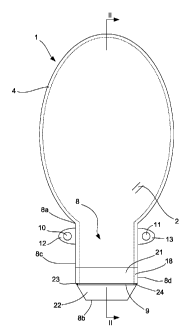
Fig. 1 shows a plane view of an embodiment of a collecting bag
according to the invention, seen from the side intended to face away
from the user and in a first position;
Fig. 2 shows a longitudinal section of the collecting bag along
the line II-II in Fig. 1;
Fig. 3 shows, on a larger scale, a perspective view of a detail of
the discharge portion of the collecting bag according to the invention;
Fig. 4 shows a sectional view along the line IV-IV of the detail
shown in Fig. 3; and
Fig. 5 shows a view corresponding to Fig. 4 of the detail of the
discharge portion of the collecting bag according to the invention in a
second and folded position.
Detailed description of preferred embodiments
In Fig. 2 some sectional areas are indicated by fully drawn lines
in order not to impede the clear reading of the drawings.
The collecting bag shown in the drawings is designed as a reus-
able ostomy bag and comprises a bag member 1 and a discharge portion
8 having a discharge opening 9, through which the collecting bag may be
emptied of its contents. The general principles relating to such an
ostomy bag are well known and common. One example of an ostomy
bag is, for instance, disclosed in Applicant's international published
application No. WO 2004/030584.
The collecting bag may assume a number of different positions,
depending on whether the bag is in its discharge position, in an
intermediate position in which the bag is closed but not locked, in a
position of use in which the bag is closed and locked, or in any other
position. In Figs. 1 and 2, the collecting bag assumes a position which
will be referred to simply as "a first position". This first position may for
instance correspond to the position the collecting bag has when it is
CA 02648365 2008-10-03
WO 2007/115575 PCT/DK2007/050041
8
supplied and to the position the collecting bag has just before the
discharge portion 8 is opened to release the contents.
The bag member 1 and the discharge portion 8 are formed by
first and second film blanks 2,3 which in a substantial part of the bag are
joined along their edges in any suitable manner, preferably by means of
one or more welding seams. In the embodiment shown the film blanks
2,3 in the bag member 1 are joined by one continuous seam 4, whereas
the joining of the film blanks 2,3 in the discharge portion 8 is to be
described further below. Preferably, and in the embodiment shown, the
discharge portion 8 is formed by end sections of the film blanks of the
bag member. Other solutions are possible, including those in which the
film blanks of the discharge portion are made as separate film blanks
joined to the film blanks of the bag member in any suitable manner.
The film blanks may be made from a suitable flexible plastic
sheet or foil material. This material should to some extent be stretchable
and possess at least some degree of elasticity. Each film blank 2,3 has
an inner side that is intended to face the contents of the bag and an
outward facing outer side. The outward facing side of the first film blank
2 is intended to face away from the user in a position of use; hence, the
first film blank 2 may be said to form the front wall of the collecting bag.
Correspondingly, the second film blank 3 has an outer side intended to
face the user in a position of use, and thus forms the back wall of the
collecting bag.
In the bag member 1, an inlet opening 5 is provided in the sec-
ond film blank 3. The inlet opening 5 is, in a manner known per se,
surrounded by connecting elements 6 for connection of the bag to a
body orifice, i.e. in this case an intestinal orifice in the form of a so-
called stoma in the user's abdominal wall.
At a distance from the inlet opening 5, the discharge portion 8
starts at a proximal or neck end 8a adjacent the bag member 1 and
extends in a longitudinal direction of the discharge portion 8 to a distal
or terminal end 8b. The end sections of the film blanks 2,3 are joined
along opposed side edges 8c and 8d.
The second film blank 3 has dimensions corresponding to that of
CA 02648365 2008-10-03
WO 2007/115575 PCT/DK2007/050041
9
the entire collecting bag, i.e. including the bag member 1 as well as the
discharge portion 8, and ends at a distal end edge 3b (cf. Fig. 2)
coinciding with the distal end 8b of the discharge portion 8. The first film
blank 2 has substantially the same dimensions in the bag member 1, but
is slightly shorter than the second film blank 3 measured in the
longitudinal direction of the discharge portion 8 and ends in a distal end
edge 2b. As the second film blank 3 is thus relatively longer, an
extension 3e of the second film blank 3 is provided.
In order to provide for sealing closure of the collecting bag, a
closure device is provided in the discharge portion 8. As mentioned in
the above, the fundamental principle underlying the closure mechanism
in this kind of collecting bag kind is that two plate members are brought
into contact with each other in an initial folding operation of the
discharge portion 8 in its longitudinal direction. This will be described in
further detail below.
A first plate member 21 is provided on the first film blank 2,
such that a distal edge 21b of the first plate member 21 is positioned
near or at the distal end edge 2b of the first film blank 2. A second plate
member 22 is provided on the extension 3e of the second film blank 3
such that a proximal edge 22a is positioned opposite the distal edge 21b
of the first plate member 21 such that the proximal edge 22a and the
distal edge 21b face each other. In the embodiment shown, the first
plate member 21 is positioned on the front side of the discharge portion
8, i.e. on the outer side of the first film blank 2, and the second plate
member 22 is positioned on the front side of the discharge portion 8 as
well, i.e. on the inner side of the extension 3e. Each of the first and said
second plate members 21, 22 has a predetermined height in the
longitudinal direction of the discharge portion between a proximal edge
21a, 22a and a distal edge 21b, 22b, respectively. The plate members
21, 22 may be connected with the respective film blank 2, 3 in any
suitable manner, for instance attached to the film blanks in a welding
operation as will be described in connection with the description of the
manufacture of the bag. In the first position shown in Figs. 1 and 2, the
first and second plate members 21, 22 are situated one after the other in
CA 02648365 2008-10-03
WO 2007/115575 PCT/DK2007/050041
the longitudinal direction of the discharge portion 8 and substantially in
parallel with each other.
The discharge opening 9, through which the bag may be emp-
tied of its contents, is formed in the discharge portion 8. In principle, the
5 discharge opening 9 is provided as a slit-shaped opening between the
two film blanks 2,3, namely as an opening between the extension 3e of
the second film blank 3 and the distal end edge 2b of film blank 2. In the
embodiment shown, however, the discharge opening 9 is delimited in
the longitudinal direction of the discharge portion 8 by the distal edge
10 21b of the first plate member 21 and thus extends between the distal
edge 21b of the first plate member 21 and the proximal edge 22a of the
second plate member 22, as the facing edges 21b, 22a are positioned on
opposite sides of said discharge opening 9. The discharge opening 9 thus
has a substantially transverse configuration relative to the longitudinal
direction of the discharge portion 8 and extends from a first side to a
second side. As will be described in further detail below, the discharge
opening 9 is delimited in the transverse direction, substantially
perpendicular to the longitudinal direction, by a strap member 23, 24 at
each side of the discharge opening 9, thus making a total of two strap
members. Consequently, the discharge opening 9 does not extend quite
from one side edge 8c to the other side edge 8d but is separated from
the side edges by the strap members.
In a manner known per se, the bag is brought from the open or
discharge position, via the first position shown in Figs. 1 and 2, via an
intermediate closed position, a detail of the collecting bag being shown
in a second and closed position in Fig. 5, to a position of use (not
shown), in which the bag is closed and locked, by a number of folding
operations and in a manner that will be described in further detail below.
The discharge portion 8 is foldable and unfoldable by at least
one folding in its longitudinal direction between the distal and proximal
ends to bring the discharge portion from an open unfolded condition to a
closed folded condition and vice versa. In the first position referred to in
the above, and described in connection with Figs. 1 and 2, the collecting
bag is unfolded and the plate members are situated one after the other
CA 02648365 2008-10-03
WO 2007/115575 PCT/DK2007/050041
11
and substantially parallel with each other. In this first position, the
contents of the bag may in principle seep or flow out of the discharge
opening. However, in the discharge position, in which the collecting bag
is hence also in an open unfolded condition, the plate members 21, 22
may be flexed slightly by applying opposite forces to the side edges 8c,
8d of the discharge portion 8 in the area of the plate members 21, 22
such that the side edges are moved towards each other in order to
enlarge the opening area. In the closed folded condition, the first and
second plate members 21, 22 are in contact with each other. The term
"closed" is to be interpreted as meaning sealingly closed such that
virtually no material (faeces) present in the collecting bag may travel
from the inside of the bag to the outside. This closed condition is
attained already when the discharge portion 8 has been folded once such
that the plate members have been brought into contact with each other
into the above-mentioned closed folded condition. "Locked" should be
interpreted to describe a condition, in which there is no need for a user
to keep the discharge portion 8 in its folded position manually.
Consequently, the bag will have reached its closed condition before it
reaches its locked condition.
When closing the bag, the discharge portion 8 is folded starting
from the distal end by initially folding the second plate member 22
against the first plate member 21, using the distal edge 21b of the first
plate member 21 as a pivot. Following this initial folding, the intermedi-
ate position, which represents a closed folded condition, shown in Fig. 5
is attained. This initial folding will have a slight stretching effect on the
material of the second film blank 3. During this folding, and in the
intermediate position as well as in the position of use, the strap
members 23, 24 connected with the film blank 3 as well as to the plate
members 21, 22 act as reinforcement of the film blank 3 An effectively
sealed closure of the discharge opening 9 is thus provided.
In order to keep the collecting bag in the closed and locked po-
sition, a locking device is provided, which in the embodiment shown
comprises foldable locking strips 12 and 13 projecting from the side
edges 8c and 8d of the discharge portion 8 at the proximal end 8a
CA 02648365 2008-10-03
WO 2007/115575 PCT/DK2007/050041
12
thereof. The projecting foldable locking strips 12 and 13, which may be
formed integrally with one of or both the film blanks 2,3, are provided
with a first set of locking means, for instance of the hook-and-loop type,
which in the embodiment shown is constituted by hook elements 10,11,
but which may also comprise snap fastening members, different types of
adhesive members etc. and are releasably engageable with a second set
of mating locking means provided on the outer side of the second film
blank 3. In the embodiments shown, a plate 14 of loop elements
constitutes the second set of locking means. It should be noted that the
locking device may be designed in other ways, e.g. as described in
applicant's International application No. WO 99/25278, or as a
traditional locking clip.
Consequently, following the initial folding the discharge portion
8 is folded again, in the embodiment shown two more times, until the
locking means 14 are brought into alignment with the projecting locking
strips 12 and 13 which are then folded to bring the locking means 10
and 11 into engagement with locking means 14.
Turning now in particular to Figs. 3 and 4, the configuration of
the plate members 21, 22 and the surrounding areas adjacent the
discharge opening 9 will be described in detail.
In the position shown, the first and second plate members 21,
22 are situated in such a way on the discharge portion 8 of the collecting
bag that a small clearance defining a distance d, occurs between the
edges facing each other, i.e. the proximal edge 22a of the second plate
member 22 and the distal edge 21b of the first plate member 21. The
distance d may be predetermined according to the materials and
dimensions of, i.a., the film blanks and plate members, and corresponds
to the height of the strap members 23, 24 in the longitudinal direction of
the discharge portion.
Generally, the predetermined distance d between the facing
edges 21b, 22a should be smaller than the total sum tl + t2 of the
thickness tl of the first plate member 21 and the thickness t2 of the
second plate member 22. Preferably, the distance d is in the range from
25-90%, preferably 28-70%, and most preferably 30-45%, of the total
CA 02648365 2008-10-03
WO 2007/115575 PCT/DK2007/050041
13
thickness tl + t2 of the first plate member 21 and the second plate
member 22. In one example corresponding to the embodiment shown, tl
is approximately 0.7 mm and t2 approximately 0,9 mm in the area
adjacent the discharge opening 9. As the distance d is approximately 0.5
mm, this results in a ratio of approximately 31%.
The thickness of the strap members 23, 24 is preferably chosen
such that the thickness t of each strap member 23, 24 is substantially
larger than the thickness of each film blank. Typical values of the
thickness are 0.15-1 mm, whereas the thickness of the film blanks is
approximately 75 m (0.075 mm). As the thickness of the strap
members is also related to the thickness of the plate members and to
the distance d between them in order to obtain a sealing closure of the
discharge portion, it is preferable to choose the thickness t in the range
50-100%, preferably 75-85%, of the distance d between the distal edge
21b of the first plate member 21 and the proximal edge 22a of the
second plate member 22. In the example corresponding to the
embodiment shown, the thickness t is approximately 0.40 mm, thus
resulting in a ratio of approximately 80%.
In the embodiment shown the strap members 23, 24 are
formed integrally with the plate members 21, 22 to form a single unit,
but they may in principle be connected to the plate members 21, 22 in
any suitable manner. For instance, the strap members may be formed as
separate parts connected with the plate members, or as parts integral
with only one of the plate members to be connected with the other plate
member in any suitable manner. The strap members 23, 24 are
connected with at least the second film blank 3, either in the same
operation as the attachment of one or both of the plate members 21, 22
to the respective film blank, or in a separate operation. The strap
members may also be made from another material than one or both of
the plate members, either as co-moulded parts of another material, or
as at least partly separate parts of another material, including for
instance extended or folded-over portions of one or both of the film
blanks of the discharge portion. It is also conceivable to form the strap
members with a height, i.e. length in the longitudinal direction of the
CA 02648365 2008-10-03
WO 2007/115575 PCT/DK2007/050041
14
discharge portion, larger than the distance d between the facing edges to
provide for an overlap of the strap members and one or both plate
members. In the embodiment shown, the number of strap members is
two, one at each side of the discharge opening. It is also possible to
have more than one strap member in each side, e.g. two narrow strap
members in a side-by-side relationship.
The strap members 23, 24 fulfil the double function of facilitat-
ing the manufacture of the collecting bag, and of securing a proper
functioning of the collecting bag during its entire period of use.
As will described in further detail in connection with the below
description of the method of manufacture, the strap members serve to
protect the film blanks during the joining operation. The advantages
obtained during manufacture are increased even further in the
embodiment comprising strap members integral with the plate member;
in this embodiment, the strap members keep the plate members
together during handling in the manufacturing process.
When the collecting bag is in use, another advantage appears:
The strap members serve to increase the strength of the hinge
constituted by the film blank when folding the discharge portion.
Depending on the degree of stretchability and resilience in the plane of
the film blanks and other factors, such as the thickness of the respective
plate members, the distance d between the facing edges has a tendency
to widen during use of the collecting bag, i.e. when a number of folding
and unfolding operations have been carried out. The presence of the
strap members makes it possible to maintain a substantially constant
distance and hence secure sealing closure of the discharge portion even
after a large number of folding operations.
Further measures to manage varying positions of the plate
members and control the folding operation comprise providing at least
one of the facing edges 21b, 22a of the plate members 21, 22 with a
fillet or chamfer 21c, 22c. In the embodiment shown, each plate
member 21, 22 is provided with a chamfer 21c, 22c extending in the
entire width of the respective plate member 21, 22. Each chamfer 21c,
22c extends in a part of the thickness direction of the first and second
CA 02648365 2008-10-03
WO 2007/115575 PCT/DK2007/050041
plate member 21, 22, the chamfers being situated such that the facing
edges 21b, 22a are substantially perpendicular to the film blanks 2 and 3
at the connection of the plate members 21, 22 to the respective film
blanks 2 and 3, whereas the outward facing edges are chamfered to
5 form a substantially funnel-shaped cross-sectional configuration. The
chamfer may extend in a part of the facing edges in the range 30 to 70%
of the thickness of the respective plate member in the area adjacent the
discharge opening 9, here approximately 50%. The chamfer angle may
vary as well, but is conveniently about 45 degrees.
10 This effect may be maintained or increased even further by
making at least one of the facing edges softer, e.g. by co-moulding the
material of the plate members with a foam material in the area adjacent
the discharge portion, in addition to making the facing edges chamfered,
filleted or rounded. Furthermore, it is possible to vary the degree of
15 resilience or elasticity of at least the second film blank, or to provide
the
attachment between at least the second plate member and the film
blank with some elasticity. The distance between the facing edges is
preferably optimised with respect to thickness and stiffness of the plate
members on one hand and the elasticity, tensional strength and
stretchability of the film blanks on which the plate members are
arranged on the other.
It might even be possible to position the plate members in such
a manner that the distance between the facing edges is substantially
eliminated. In this manner welding is still possible but the advantages
during use are not present.
With respect to the overall shape of the plate members, the first
plate member 21 has a generally rectangular shape, whereas the second
plate member 22 has a generally trapezoid shape, the second plate
member 22 having at the proximal edge 22a a width w corresponding
substantially to the width of the first plate member 21 at the distal edge
21b.
As mentioned in further detail in Applicant's above-mentioned
international published application No. WO 2004/030584, it is possible to
form the first plate member 21 with a larger height than the second
CA 02648365 2008-10-03
WO 2007/115575 PCT/DK2007/050041
16
plate member 22. The ratio between the heights of the first and the
second plate member may e.g. lie in the interval from 1:1 to 4:1
depending on the height of the first plate member. The second plate
member 22 should, however, have such a height that it has sufficient
torsional strength and stability in order to allow the folding operations to
be carried out properly. The width of each of the plate members 21,22
should be larger than the distance between the joints at each side edge
8c,8d and may e.g. be such that the plate members extend over the
entire width of the discharge portion. The dimensions of the first plate
member may vary, e.g. within an interval of the height-width ratio
ranging from 1:7 to 1:2.
Furthermore, it is noted that the first plate member 21 may
have a recess delimiting an area corresponding in substance to the
shape of the second plate member 22. Although the thickness of the first
plate member 21 is only reduced to some extent in the area adjacent the
discharge opening 9, such a recess may provide for partial accommoda-
tion of the second plate member 22 when the discharge portion 8 has
been folded to bring the first and second plate members 21, 22 into
contact with each other.
The manufacture of the collecting bag in general and of the
plate members at the discharge portion in particular will now be
described in further detail.
In short, the method comprises the steps of providing a first
film blank, providing a second film blank with an extension, joining the
first and second film blanks in a first continuous seam to provide the bag
member, attaching a first plate member on the first film blank, and
attaching a second plate member on the extension of the second film
blank. The steps particular to the inventive method include the steps of
providing at least two strap members having at least the same thickness
as each film blank between the plate members, and joining the first and
second film blanks in a second continuous seam for providing said
discharge portion having a discharge opening, said seam extending at
least along side edges of the first and second plate members and along
said strap members.
CA 02648365 2008-10-03
WO 2007/115575 PCT/DK2007/050041
17
As mentioned in connection with the description of Figs. 1 to 5,
it is preferred that the strap members and plate members are provided
as a unit, preferably by means of moulding. The unit is preferably
provided with dimensions exceeding the dimensions of the discharge
portion, further comprising the step of removing surplus material from
said unit by means of cutting, punching or the like.
The plate members 21, 22 and the strap members 23, 24,
whether or not they are provided as an integrated unit, may be made
from a suitable material, such as polyethylene (PE), polypropylene (PP),
a copolymer of PE and ethylene vinyl acetate (EVA), nylon. The plate
members and the strap members may e.g. be formed from the same
material as the film blanks, although in a considerably larger thickness.
The plate members may be made from identical materials and have the
same thickness, or possess different properties in varying areas of the
plate members.
Referring to the principles set out in the above and to the em-
bodiment shown in Figs. 1 to 5, the collecting bag may be manufactured
in the following manner:
1) The material to form the second film blank 3 is un-
wound from a roll.
2) An aperture is punched to form the inlet opening 5.
3) Connecting elements 6 are attached to the second
film blank 3.
4) The material to form the first film blank 2 is un-
wound from another roll.
5) The first and second film blanks are joined to each
other by means of a first welding operation to pro-
vide the seam 4 to form the bag member.
6) In the area of the discharge portion 8, the second
film blank 3 is folded upwards towards the bag
member 1.
7) The unit comprising the plate members 21, 22 and
the strap members 23, 24 is attached to the first
film blank 2 by means of a welding tool in the area
CA 02648365 2008-10-03
WO 2007/115575 PCT/DK2007/050041
18
of the first plate member 21.
8) Following the repositioning of the second film blank
3 to the discharge portion 8, the entire discharge
portion 8 is welded by means of a welding tool to
provide seam 18 in the area of the strap members
23, 24 and the second plate member 22.
9) Surplus material surrounding the contours of the fin-
ished collecting bag is removed in a punching opera-
tion.
During step 7) the second film blank 3 is not affected at all, and
during step 8) the strap members 23, 24 protect the second film blank 3
by absorbing part of the heat from the welding tool.
The collecting bag may be provided with further details, such as
a deodorizing filter, additional film blanks to provide a one-way valve
within the bag member, comfort layers made from e.g. non-woven
overlapping the outward facing sides of the film blanks, devices for
retaining the folded discharge opening positioned in other places than
plate 14 etc, e.g. beneath a comfort layer.
The invention should not be regarded as being limited to the
embodiments described in the above but various modifications and
combinations of the shown embodiments may be carried out without
departing from the scope of the following claims.
For example, although the invention has been described only
with reference to a collecting bag having two plate members, both of
which are positioned on the outer side of the respective film blank, other
configurations are conceivable as well, including those having more than
two plate members and those in which it is the front film blank that is
provided with an extension.