Note: Descriptions are shown in the official language in which they were submitted.
CA 02648639 2008-10-27
WO 2007/121535 PCT/AU2007/000541
POWER TOOL
BACKGROUND OF THE INVENTION
Field of the Invention
This invention relates to a hand held power tool having an operative
element for treating the face of a work piece. The power tool is of the kind
that
has a base positionable in use adjacent a work piece, an operative element
that
is rotatable about an axis, whereby the operative element is also movable in
the
direction of the axis relative to the base to treat the work piece. One form
of
power tool to which the invention applies is a router, and it will be
convenient to
hereinafter describe the invention with reference to this form of power tool.
It
should however be appreciated that the invention is not limited to that
application and can apply to other forms of power tools.
Description of the Prior Art
The following discussion of the background to the invention is intended to
facilitate an understanding of the invention. However, it should be
appreciated
that the discussion is not an acknowledgement or admission that any of the
material referred to was published, known or part of the common general
knowledge as at the priority date of the application.
Plunging type routers are one form of power tool used to cut shapes into
wooden, plastic or metal work pieces. These types of routers include an
electric
motor having an output shaft on which a cutting tool for treating the surface
of a
work piece is attached. The electric motor is typically enclosed within a
housing
which includes substantially all of the controls and componentary of the
router.
The housing is movably mounted on one or more columns extending from a
base plate which supports the housing above the work piece. The router can
be moved over the surface of the work piece using one or more handles
attached to the housing of the router.
A user operates the router by gripping the handles, positioning the base
plate over the desired portion of the work piece, turning the motor on using
the
CA 02648639 2008-10-27
WO 2007/121535 PCT/AU2007/000541
2
controls on the housing and then lowering the housing and cutting tool along
the
columns to plunge the operative element past the base plate into the work
piece. Stops are normally provided on the columns to limit the depth of the
plunge to a selected depth.
The operation of such a router requires a high degree of skill in order to
successfully position, plunge and control the apparatus in a single action. In
this regard, appreciating the face of the work piece, depth of plunge
required,
lowering speed of the cutting tool and correct setting of the position of the
stops
can be difficult to determine manually. Furthermore, due to the configuration
of
the housing and handles, the cutting tool can be obscured by the bulk of the
motor housing during operation when the operator views the work piece and
router from above. This makes it difficult guiding the cutting tool in the
horizontal
plane, which can lead to the cutting tool plunging in the wrong location.
It would therefore be desirable to provide a power tool that is relatively
easy to use. It would be preferred that the power tool be designed to make the
plunging operation of the tool easier to control during operation of the tool.
It
may also be preferred that the power tool provides improved vision of the
operative element when in use.
SUMMARY OF THE INVENTION
According to one aspect of this invention there is provided a hand held
power tool for use with an operative element to treat a work piece over a
treatment depth from a face of the work piece, the power tool including:
a base positionable in use adjacent the work piece;
a fastening assembly for holding the operative element, the fastening
assembly being rotatable about an operative axis, the fastening assembly being
movable relative to the base in the direction of the operative axis;
primary power drive means including a motor being operable to rotate
the fastening assembly about the operative axis;
secondary power drive means including a motor being operable to move
the fastening assembly relative to the base in the direction of the operative
axis;
CA 02648639 2008-10-27
WO 2007/121535 PCT/AU2007/000541
3
electronic control means for controlling at least the operation of the
secondary power drive means, the electronic control means having user
controls; and
at least one handle which is held by the user while operating the power
tool,
wherein the user controls are located on the at least one handle to
enable user operation of the secondary power drive means while holding the at
least one handle.
The power tool according to the present invention includes an
electronically controlled (secondary) power drive for moving, and in the case
of
a router, plunging the operative element to treat a work piece over a
treatment
depth from a face of the work piece. The electronic control means controlling
the movement of the operative element have user controls located on the
handle for the tool which the operator grips when operating the tool. This
location allows a user accessible, safer, more convenient, and in some cases
more ergonomic control of the tool during operation. Moreover, a user need not
let go of the handle during operation of the tool to modify or adjust
operation of
the operative element, as such adjustments can be achieved through
manipulation of the controls located on the handle of the tool.
The user control means located on the at least one handle can include
further control means for controlling other functions of the power tool. These
control means may or may not be linked to the electronic control means.
In some embodiments, the electronic control means also includes user
control means located on the at least one handle for controlling the operation
of
the primary power drive means. A switch or control means controlling power
functions of the tool can also be included in the at least one handle of the
power
tool. More preferably, the at least one handle includes a switch which locks
on
the power of the power tool.
In some embodiments, there is provided at least one user control on the
at least one handle for fine adjustment of the movement of the operative means
CA 02648639 2008-10-27
WO 2007/121535 PCT/AU2007/000541
4
along the operational axis. Preferably, the user control means for fine
adjustment of the movement of the operative means is connected to the
electronic control means. In this respect, the at least one handle includes a
control which allows low speed or fine control of the secondary power control
means via the electronic control means. This particular control is useful for
changing the zero surface depth calibration of the power tool.
In some embodiments, the user controls on the at least one handle
includes a means for selecting an adjustment mode of the electronic control
means and an adjustment controller for adjusting the parameters in that mode.
The adjustment mode is preferably selected from at least one of the secondary
power drive means, primary power drive means, rotation of the operative
element, or plunging speed of the operative element.
The primary power drive means rotates the operative element at a
rotating speed. In some embodiments, the rotating speed can be controlled by
the electronic control means, preferably through user controls located on the
at
least one handle. It is further preferred that the rotating speed is
adjustable to
suit specifications of the operative element and the work piece.
Any number of arrangements of handles can be used for an operator to
hold during operation of the power tool according to the present invention
including two or more handles, one or more of the user controls for the
electronic control means being located on one or more of the handles.
In some embodiments, the handle is located proximate to the primary
power means. However, it is more preferable for the at least one handle to
extend from the base of the power tool. Preferably, each handle is integrally
formed with the base of the power tool.
It should be appreciated that the positioning of the handles on the base
can provide a user with greater stability and control over the tool in
comparison
to when the handles extend from other locations on the tool. For example, in
some configurations the handles can be attached to a housing which is movable
CA 02648639 2008-10-27
WO 2007/121535 PCT/AU2007/000541
mounted above the base, the housing moving along the operative axis during
operation of the tool. When operating such tool, a user must compensate for
and control axial movement of the handles along the operative axis in addition
to the other parameters required for treating the work piece. In comparison,
5 when the handles are attached to the base, the handles are stationary
relative
to the operative axis, and therefore afford greater stability and control of
the tool
when treating the work piece.
Any number of handles can extend from the base. In some
embodiments, two or more handles extend from the base. Preferably, each of
the handles is spaced apart about the perimeter of the base of the tool. More
preferably, when the tool includes two handles, each handle extends from
generally opposite locations on the base.
The powered plunging configuration provided by the secondary power
drive can take a number of forms. In one embodiment, the hand held power
tool includes an output shaft extending from the motor of the primary power
drive means. The output shaft extends coaxially with the operative axis with
the
fastening assembly located at a distal end of the output shaft. In such a
configuration, the secondary power drive means is preferably operatively
associated with the primary power drive means so that operation of the
secondary power drive means moves the primary power drive means and the
fastening assembly relative to the base. This association can take many forms.
In one embodiment, the secondary power drive means includes a screw
drive and a geared connection between the motor of the secondary power drive
and the screw drive. This geared connection preferably includes a drive
member located on an output shaft of the motor of the secondary power drive
means and a driven member associated with the screw drive. The screw drive
typically includes a threaded shaft fixed in position relative to the base.
The
driven member typically has a threaded bore for locating the driven member on
the shaft so that rotation of the driven member about the shaft causes
movement of the driven member along the shaft.
CA 02648639 2008-10-27
WO 2007/121535 PCT/AU2007/000541
6
In some embodiments of the invention, the power tool further includes a
housing which houses the primary power drive means and secondary power
drive means, the housing being movable relative to the base in the direction
of
the operative axis. In such embodiments, movement of the driven member
along the shaft can therefore result in movement of the primary drive means
and the fastening assembly relative to the base. In this respect, the power
tool
can be configured to allow the driven member to engage the primary power
drive means so as to move therewith relative to the base. The driven member
may directly or indirectly engage the primary drive means.
In another embodiment, the hand held power tool includes an output
shaft extending from the motor of the primary power drive means wherein the
output shaft extends parallel to the operative axis. The drive shaft assembly
extends parallel to the output shaft of the motor of the primary power drive
means, and operatively connects the primary power drive means to the
operative element. The drive shaft assembly is also adjustable in a direction
of
the operative axis to move the fastening assembly relative to the base with
the
secondary power drive means being operatively associated with the drive shaft
assembly so that operation of the secondary power drive means adjusts the
drive shaft assembly.
In some embodiments of the invention, the drive shaft assembly includes
at least two elements that rotate about the operative axis and that move
relative
to each other in the direction of the operative axis to adjust the drive shaft
assembly. In this embodiment, the drive shaft assembly can include a drive
element in driving engagement with a driven element, and a sleeve within which
the driven element rotates, the sleeve being connected to the secondary power
drive means so that operation of the secondary power drive means moves the
sleeve and the driven element in the direction of the operative axis. In this
respect, the driven element is operatively associated with the fastening
assembly and the secondary power drive means so that operation of the
secondary power drive means moves the driven element relative to the drive
element to move the fastening assembly relative to the base. The motor of the
secondary power drive means preferably drives a threaded output shaft on
CA 02648639 2008-10-27
WO 2007/121535 PCT/AU2007/000541
7
which shaft is located a driven member having a threaded bore, the driven
member is connected to the sleeve so that rotation of the output shaft moves
the driven member along the threaded shaft and moves the sleeve with the
driven element and fastening assembly relative to the base. More preferably,
the output shaft from the motor of the primary power drive means is in driving
engagement with the drive element of the drive shaft assembly so that rotation
of the output shaft rotates the drive element.
In one form, the secondary power drive controls movement
characteristics of the fastening assembly over the treatment depth. The
movement characteristics include plunging speed and/or plunging force. The
movement characteristics may be controllable by the electronic control means,
a gearbox or both. The plunging force may also be controllable by the
electronic control means, a gearbox or both. The gearbox may include a
plurality of gears that are operable for providing respective movement
characteristics settings. The gearbox may further include a means for
mechanically selecting one of the gears and its respective movement
characteristics setting. In addition, or alternatively, the power tool may
include a
means for electronically selecting one of the gears and its respective
movement
characteristics setting. The means for selecting the one of the gears may
include a motorised gear selection mechanism.
The preferred form of hand held power tool is a router, and the preferred
form of operative element is a router bit.
According to another aspect of the invention there is provided a
microcontroller for use with a hand held power tool for use with an operative
element to treat a work piece over a treatment depth from a face of the work
piece. The power tool includes a base positionable in use adjacent the work
piece; a fastening assembly for holding the operative element, the fastening
assembly being rotatable about an operative axis, the fastening assembly being
movable relative to the base in the direction of the operative axis; primary
power
drive means including a motor being operable to rotate the fastening assembly
about the operative axis; secondary power drive means including a motor being
CA 02648639 2008-10-27
WO 2007/121535 PCT/AU2007/000541
8
operable to move the fastening assembly relative to the base in the direction
of
the operative axis; at least one handle which is held by the user while
operating
the power tool; and user controls located on the at least one handle to enable
user operation of the secondary power drive means while holding the at least
one handle. The microcontroller includes a processing unit and associated
memory device for storing control logic to cause the microprocessor to receive
control inputs from the user controls; and control operation of the secondary
power drive means in accordance with the control inputs.
Preferably, the control logic further acts to cause the microprocessor to
control operation of the primary power drive means in accordance within the
control inputs.
The primary power drive means rotates the operative element at a
rotating speed. The control logic preferably further acts to cause the
microprocessor to control the rotating speed in accordance with the control
inputs.
The control inputs may be indicative of user selection of an adjustment
mode and user selection of parameters in that mode. In this case, the control
logic may further act to cause the microprocessor to control operation of at
least
one of the secondary power drive means, primary power drive means, rotation
of the operative element, or plunging speed of the operative element in
response to user selection of the adjustment mode and parameters.
The control logic may further act to cause the microprocessor to adjust
the rotating speed to suit specifications of the operative element and the
work
piece.
The secondary power drive may move the fastening assembly over the
treatment depth at a plunging speed. In this case, the control logic may
further
act to cause the microprocessor to control the plunging speed in accordance
with the control inputs
CA 02648639 2008-10-27
WO 2007/121535 PCT/AU2007/000541
9
The control logic may further act to cause the microprocessor to adjust
the plunging speed to suit specifications of the operative element and the
work
piece.
The secondary power drive includes a gearbox having a plurality of gears
that are operable for providing respective plunging speed settings, and the
power tool includes a means for electronically selecting one of the gears and
its
respective plunging speed setting. In this case, the control inputs act to
cause
the microprocessor to control the electronic selection of gears.
BRIEF DESCRIPTION OF THE DRAWINGS
It will be convenient to hereinafter describe the invention in greater detail
by reference to the accompany drawings which show two preferred
embodiments of the invention. The particularity of the drawings and the
related
detailed description is not to be understood as superseding the generality of
the
preceding broad description of the invention.
Figure 1 is a perspective view of a first preferred embodiment of a power
tool according to the present invention.
Figure 2 is further perspective view of the power tool shown in Figure 1
having a portion of the housing removed to show the location of a primary
power drive means, secondary power drive means, drive shaft assembly,
fastening assembly and operative element.
Figure 3 is a front elevational view of the power tool shown in Figure 1
including cut out side views of each handle of the power tool.
Figure 3a is a left hand side view of the left hand grip of the router shown
in Figure 3.
Figure 3b is a right hand side view of the right hand grip of the router
shown in Figure 3.
CA 02648639 2008-10-27
WO 2007/121535 PCT/AU2007/000541
Figure 4 is a block diagram illustrating the connections between each of
the elements of the power tool shown in Figure 3.
5 Figure 5 is a front elevational view of a second preferred embodiment of
the power tool according to the present invention.
Figure 5a is a left hand side view of the left hand grip of the router shown
in Figure 5.
Figure 6 is a block diagram illustrating the connections between each of
the elements of the power tool shown in Figure 5.
Figure 7 is a schematic diagram of the printed circuit board forming part
of the control circuiting of the power tool shown in Figures 3 and 5.
Figure 8 is a front elevational view of an alternative embodiment of the
secondary power drive means of the power tool shown in Figure 1 including a
portion of the housing attached to the secondary power drive means and a two
speed gearbox arrangement.
Figure 9 is a side section view of the secondary power drive means
shown in Figure 8 illustrating components of the secondary power drive means
including a two speed gearbox.
Figure 10 is a side view of components of the secondary power drive
means shown in Figure 8.
DETAILED DESCRIPTION
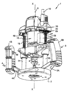
Referring to Figure 1, there is illustrated a hand held router 1 which
incorporates one preferred form of power tool according to the present
invention. The router 1 includes a generally circular base 2 which in use, is
positionable adjacent a work piece such as a timber panel (not shown) using a
CA 02648639 2008-10-27
WO 2007/121535 PCT/AU2007/000541
11
pair of handles 3, 4. Each of the handles 3, 4 include a trapezoidal shaped
extension member 3A, 4A and a generally rectangular shaped hand grip 3B, 4B
attached to the distal end thereof. Each of the extension members 3A, 4A
extend outwardly from opposite sides of the perimeter of the base 2 at an
upwardly angle relative to the base 2. The length of the connecting hand grips
3B, 4B extend perpendicularly to the length of each extension members 3A, 4A
thereby providing a vertically orientated gripping region when the router 1 is
used in the normal operational orientation, as shown in Figure 1. Each of the
hand grips 3B, 4B include a set of controls 40, 42, 44, 46 which will be
described in greater detail later in the specification.
A pair of cylindrical columns 34, 35 extend from an upper surface of the
base 2 from opposite sides of the base 2, adjacent to the location where the
handles 3, 4 extend from the base 2. A housing arrangement 5 is supported
above the base 2 on the columns 34, 35. The housing 5 encloses the operative
components of the router 1 and is (in at least the illustrated embodiment)
movable relative to its base 2 about columns 34, 35. It should however be
appreciated that in some alternative embodiments, the router 1 could be
configured with the housing 5 being stationary relative to the base 2. A
cylindrical power conduit 10 extends from a top corner of the housing 5. As
can
be appreciated, the total length of the power conduit 10 has not been
illustrated,
and would normally extend through a length of cord ending with a power plug at
its free end.
An operative element or router bit 7 for treating the face of a work piece
is shown in a position spaced between the housing 5 and the base 2. The router
bit 7 includes a fastening portion (not illustrated) which is fastened within
and
held by a fastening assembly or more specifically a collet 8 which extends out
of
the base of the housing 5. The router bit 7 can be secured within and removed
from the collet 8 by actuation of spindle lock button 9, which is connected to
an
internal locking means (not illustrated) of the collet 8. In operation, the
collet 8
and router bit 7 are rotated about an operative axis X-X by operation of a
primary power drive means (16 in Figure 2), and movable in the direction of
the
operative axis X-X by operation of a secondary power drive means (27 in Figure
CA 02648639 2008-10-27
WO 2007/121535 PCT/AU2007/000541
12
2). Each of the primary power drive means 16 and secondary power drive
means 27 are enclosed within housing 5.
The primary power drive means 16, best illustrated in Figure 2 and the
schematic shown in Figure 3, includes an electric motor having a rotor (not
illustrated) and a stator 18. An output shaft (not illustrated) of the primary
power
drive means 16 extends from the rotor. The collet 8 is located at a free end
of
the output shaft for retaining a router bit 7. Rotation of the rotor causes
rotation
of the output shaft and therefore rotation of the router bit 7 about an
operative
axis X-X. As can be appreciated, the rotational speed of the collet 8 and
router
bit 7 can be controlled by controlling the speed of the primary power drive
means 16. This is achieved through use of an electronic control means 60
(Figure 4) and user controls 40, 42, 44, 46 on the handles 3, 4 as will be
discussed in more detail later in the specification.
As illustrated in Figures 2 and 8 to 10, the housing 5 is movable relative
to the base 2 by way of operation of a secondary power drive means 27. The
secondary power drive means 27 illustrated includes a housing 28, a motor 26
with an output shaft 29 having a geared drive wheel 36 located thereon. The
housing 5, primary power drive means 16, and attached collet 8 are mounted
about a driven sprocket 30 mounted on a threaded shaft 37 extending from one
of the columns 35. The driven sprocket 30 has a threaded bore 70, allowing the
driven sprocket 30 to move along the length of the shaft 37, and thereby
accordingly move the housing 5 and attachments. The driven sprocket 30 has a
geared perimeter which interengages with an associated geared perimeter of
the geared drive wheel 36. In operation, the geared drive wheel 36 drivingly
engages the driven member 30 so that rotation of the geared drive wheel 36
causes the driven member 30 to move relative to the threaded shaft 37.
It is preferred that the motor 26 of the secondary power drive means 27
allow for fine controlled rotation of its output shaft 29. A sensor (not
shown) may
be included to measure steps of each rotation. A resolution of 200 increments
per rotation may be suitable.
CA 02648639 2008-10-27
WO 2007/121535 PCT/AU2007/000541
13
The embodiment of the secondary power drive means 27 illustrated in
Figures 8 to 10 includes a two speed gearbox 71 provided between the motor
26 and the geared drive wheel 36. In this arrangement the output shaft 29 of
the motor 26 is indirectly coupled to the geared drive wheel 36 via the two
speed gearbox 27. The output shaft 29 is coupled to an input shaft 72 for the
gearbox 71. The gearbox 71 has a first ratio gear 73 that is operable, when
selected, for transmitting rotation of the motor output shaft 29 and the
gearbox
input shaft 72 into rotation of an output shaft 75 of the gearbox 71. The
gearbox
output shaft 75 is coupled to the drive wheel 36 such that rotation of the
gearbox output shaft 75 causes rotation of the drive wheel 36, which as
mentioned above, drives rotation of the driven member 30 and causes the
driven member 30 to move relative to the threaded shaft 37. The first ratio
gear
73 is configured so as to cause a relatively slow rate rate of rotation of the
gearbox output shaft 75, the drive wheel 36 and the driven member 30. Thus,
the first ratio gear 73 provides for a relatively slow rate of movement of the
driven member 30 relative to the threaded shaft 37 for a given rate of
rotation of
the motor output shaft 29. By providing a relatively slow rate of movement of
the driven member 30 relative to the threaded shaft 37 for a given rate of
rotation of the motor output shaft 29, the first ratio gear 73 is suitable for
selection when it is desired to have finer control of the plunging speed of
the
collet 108 and attached router bit 107. For example, when the router bit 107
is
being plunged into a relatively delicate work piece finer control of the
plunging
speed may be appropriate. It will be appreciated that the first ratio gear 73
will
also be operable for applying a relatively greater amount of torque in the
gearbox output shaft 75. This greater amount of torque will result in a
greater
plunging force being applied to the collet 108 and attached router bit 107.
Similarly, the gearbox 71 has a second ratio gear 74 that is configured,
when selected, for transmitting rotation of the motor output shaft 29 into a
faster
rate of rotation of the gearbox output shaft 75 and the drive wheel 36, which
in
turn, causes a faster rate of rotation of the driven member 30. The faster
rotating driven member 30, in turn, moves relative to the threaded shaft 37 at
a
relatively faster rate. Thus, compared to the first ratio gear 73, the second
ratio
gear 74 provides for a relatively faster rate of movement of the driven member
CA 02648639 2008-10-27
WO 2007/121535 PCT/AU2007/000541
14
30 relative to the threaded shaft 37 for a given rate of rotation of the motor
output shaft 29. By providing a relatively faster rate of movement of the
driven
member 30 relative to the threaded shaft 37 for a given rate of rotation of
the
motor output shaft 29, the second ratio gear 74 is suitable for selection when
finer control of the plunging speed of the collet 108 and attached router bit
107
is not required and instead a faster plunging speed is required. For example,
when the router bit 107 is being plunged into a relatively course work piece,
when the user is more experienced in the use of the router 1 or for some other
reason, finer control of the plunging speed may not be appropriate or required
and a faster plunging speed may be more appropriate or advantageous. It will
be appreciated that the second ratio gear 74 will also be operable for
applying a
relatively lesser amount of torque in the gearbox output shaft 75 compared to
the first ratio gear 73. This greater amount of torque will result in a
greater
plunging force being applied to the collet 108 and attached router bit 107.
As shown in Figure 10, the two speed gearbox 71 includes a gear
selection lever 76 which is accessible through an aperture 77 in the housing
28
of the secondary power drive means 27. The lever 76 is coupled to the
gearbox 71 and is configured, when operated by hand, to mechanically select
either the first ratio gear 73 or second ratio gear 74 as required. It is to
be
appreciated, however, that the router 1 may incorporate an electronically
controlled means for selecting either the first ratio gear 73 or second ratio
gear
74 which may be incorporated into other electronic control means for the
router
1. The means for selecting the first ratio gear 73 or the second ration gear
74
may include a motorised gear selection mechanism (not shown). Also, while
the embodiment of the gearbox 71 illustrated in Figures 8 to 10 incorporates
only two ratio gears 73, 74, it is to be appreciated that any number of
suitable
gears may be utilised, for example three, four or more gears.
Operation of the secondary power drive means 27 results in movement
of the driven member 30 relative to the threaded drive shaft 37, allowing the
router bit 7 to be moved from a position above the base 2, as shown in Figures
1 and 2, to a position beneath the base 2. Moreover, as the position of the
primary power drive means 16 is fixed relative to the housing 5, operation of
the
CA 02648639 2008-10-27
WO 2007/121535 PCT/AU2007/000541
secondary power drive means 27 will cause corresponding movement of the
housing 5 relative to the base 2 in the direction of the operative axis X-X.
Referring to Figures 1 and 3, there is shown the locations of a number of
5 user controls 40, 42, 44, 46 on the housing 5 and handles 3, 4 of the router
1.
As shown in Figure 4, each of the user controls 40, 42, 44, 46 is connected to
an electronic controller 60, which in turn is connected to and actuates the
mains
power 62, primary power drive means 16 and secondary power drive means 27
in response to operation of these user controls 40, 42, 44, 46.
The left hand grip 3B includes a pivot switch 40 located proximate to the
distal or free end of the grip 3B. This location allows a user to actuate the
switch 40 using the left thumb or a finger of the user's left hand. The pivot
switch 40 is arranged to be moved upwardly to actuate one control setting and
downwardly to actuate a second control setting in the electronic controller
60.
In this embodiment, the pivot switch 40 actuates operation of the second power
drive means 27 through the electronic controller 60. Accordingly, movement of
the pivot switch 40 upwardly operates the second power drive means 27 to
move the collet 8 and router bit 7 upwardly in the direction of the X-X axis,
and
movement of the pivot switch 40 downwardly in the direction of the X-X axis,
operates the second power drive means 27 to move the collet 8 and router bit 7
upwardly.
As shown in Figure 3a, the left hand grip 3B can also include a roller
switch 42 which can be actuated by the index or middle finger of a user's left
hand. In this embodiment, the roller switch 42 controls the plunge depth of
the
router bit 7 within a preselected depth range. The roller switch 42 can be
used
in conjunction with the pivot switch 40 to lower the router bit 7 to any depth
within the depth range of the router, which is typically 70mm.
As best seen in figure 3b, the right hand grip 4B includes a power trigger
44 for switching power to the primary power drive means 16. Depression of the
power trigger 44 actuates the controller 60 to switch power on to the primary
power drive, thereby powering the motor and thereby causing the collet 8 and
CA 02648639 2008-10-27
WO 2007/121535 PCT/AU2007/000541
16
router bit 7 to rotate. The power trigger 44 is preferably actuated by the
index
and/or middle finger of a user's right hand. In some forms, the power trigger
44
can provide different levels of power to the primary power drive means 16
depending on how far the trigger 44 is depressed and therefore controls the
speed of rotation of the collet 8 and router bit 7.
The right hand grip 4B also includes a power locking button 46 which
when depressed locks the power on to the primary power drive means 16.
Thereafter, power to the primary power drive means 16 can only be unlocked or
turned off by pressing the power trigger 44 which releases the power locking
button 46, or of course turning the power of at the source (mains 62, socket
or
the like). The power locking button 46 is generally used by a user when the
user wishes to operate the power the rotation of the router bit 7 for an
extended
length of time, and/or if their finger is becoming tired depressing the power
trigger 44. The button 46 can be actuated by a finger or thumb of a user's
right
hand.
Referring to Figure 3, the housing 5 includes a number of controls 48, 49
on the front facia of the housing 5.
Located at the upper right hand corner of the front of the housing 5 is a
depth dial 48. The depth dial 48 controls the plunge depth of the router bit 7
within a preselected depth range. For the illustrated embodiment the depth
range is 70mm. The depth dial 48 has incremental settings of 0.5, 1, 2, 3, 4,
5,
6, 8, 10, 15, 20, 25 mm. The depth dial 48 can be used in conjunction with the
pivot switch 40 to lower the router bit 7 to any depth within the depth range.
For example, when the depth dial 48 is set to a high setting, for instance
10mm or 15mm, the router bit 7 is enabled to move a 10mm range at the
predetermined depth. At the other extreme, the depth dial 48 could be set to a
low setting, for instance 1 mm or 0.5 mm position and therefore only allow a
very
small movement range at a selected depth. Moreover, in selected
embodiments, when set at this setting, movement of the router bit 7 along the
X-X axis actuated by pivot switch 40 is comparatively low.
CA 02648639 2008-10-27
WO 2007/121535 PCT/AU2007/000541
17
A low depth dial 48 setting is useful when making an accurate zero
surface depth calibration. In this respect, adjustment can be made by lowering
the router bit 7 using the pivot switch 40 on the left hand handle 3 until the
top
of the router bit 7 is close to the work surface. Adjustment can then be made
by
setting the depth dial 48 to the 1 mm or 0.5mm position and then using the
pivot
switch 40 to fine adjust the zero surface setting of the router bit 7.
Still referring to Figure 3, the housing 5 further includes a speed control
dial 49 at the centre of the front facia of the housing 5. The speed control
dial
49 sets the speed of the primary power drive means 16 to a particular setting
or
range of speeds. In the illustrated embodiment, the speed control dial 49
adjusts the speed of the primary power drive means 16 between 10,000 rpm to
20,000 rpm. Therefore, when the trigger switch 44 is depressed, the router bit
7
is rotated at or within a set speed range determined by the setting of the
speed
control dial 49.
Figure 4 provides a block diagram representation of the main
components of the router 1 and the connections between these components
and an electronic controller in the form of a microcontroller mounted on a
printed control board (PCB) 60. Each of the primary drive means 16, secondary
drive means 27, mains power 62, depth dial 48, speed control dial 49, pivot
switch 40, roller switch 42, power trigger 44 and power lock button 46 are
connected to the microcontroller 60. Actuation of any one or more of the depth
dial 48, speed control dial 49, pivot switch 40, roller switch 42, power
trigger 44
and power lock button 46 triggers an action in the microcontroller 60, which
in
turn actuates the appropriate response or action in one of the drive means 16,
secondary drive means 27, or mains power 62. For example, when the power
trigger 44 is actuated, the microcontroller 60 responds to this actuation by
appropriately starting the motor of the primary drive means 16.
In order to include control switches such as the pivot switch 40, roller
switch 42, power trigger 44 and power lock button 46 in the handles 3, 4 of
the
router 1, it is necessary to create a clear path of conduit through the router
1
CA 02648639 2008-10-27
WO 2007/121535 PCT/AU2007/000541
18
structure from each of the handles 3, 4 to the housing 5. In this respect,
most
past configurations of routers have included the control switches in the
housing
in order to keep the switches in close proximity to the components that these
switches are connected and control. The close proximity to components also
simplifies the wiring connections between switches and components, but can
limit the accessibility and ease of use of such controls. In comparison, the
control switches 40, 42, 44, 46 of the illustrated embodiment have been
located
in a much more accessible location, on the handles 3, 4 of the router 1. As
schematically illustrated in Figure 4, this has necessitated the inclusion of
specific pathways or conduits between the housing 5 and handles 3, 4, through
column 34 and through the base 2 and extension members 3A, 4A to create the
connections between components, controllers and switches in the illustrated
embodiment of the present invention.
Figures 5 and 6 illustrates router 50 incorporating another embodiment of
the present invention. The router 50 has substantially all the same elements
as
the previously described router 1, with the exception of the configuration of
the
control means 152 provided on the handle 103 and display 155, 156 on housing
105. Due to this similarity, each like element has been given the same
numerical designation with the addition of 100, and it should be understood
that
the foregoing description of these like elements of router 1 is equally
applicable
to the elements disclosed in figures 5 and 6 for router 50.
As shown in Figure 5a, the left hand grip 103B of the router 50 includes
an upper mode switch 152 which can be actuated by the users left hand thumb.
The mode switch 152 is used to select an adjustment mode in which the pivot
switch 140 can be used to adjust one or more parameters in that mode. In the
illustrated router 50, the mode switch 152 is connected to a microcontroller
mounted on a PCB 160 in Figure 6 which controls the functions of each of the
primary power drive means 116, secondary power drive means 127, rotation
speed of the collet 108 and router bit 107, plunging speed of the collet 108
and
attached router bit 107. Referring to Figure 6, it can be seen that actuation
of
the mode switch 152 causes the microcontroller 160 to be set into a particular
mode, say for example primary drive means 116 speed. This mode is indicated
CA 02648639 2008-10-27
WO 2007/121535 PCT/AU2007/000541
19
on the LED array 156 located on the housing 5 and will be displayed on the
LCD display screen 155, with the graphics on the screen 155 changing to show
the parameters for that particular mode. The pivot switch 140 can then be used
to adjust the parameters shown on the screen 155. Similar adjustment can be
made for controlling the secondary power drive means 127 (plunge speed,
depth, zero depth calibration or the like).
The display screen 155 and control switches or buttons 140, 144, 146,
152 can be used in some embodiments for accessing other electronic functions
of the router 50 such as metric/imperial conversions, languages, calibration
functions or the like.
It should be appreciated that the described router 1 and 50 utilise a
secondary power drive means 27, 127 to move the router bit 7, 107 relative to
the base 2, 102 which is controlled from a hand grip control switch 40, 140.
The
combination of these features makes plunging the router bit 7, 107 to the
required depth easier and allows the operator to plunge with greater precision
than existing plunging routers. It should also be appreciated that the
embodiments of the invention in which the handles 3, 4, 103, 104 are attached
to the base 2, 102 facilitates vision of the router bit 107, as this
configuration
allows a user to grip the router 1, 50 at the base 2, 102 rather than at a
more
upwardly position proximate to the housing 5, 105, which can in some
configurations of router partially obscure the operators line of sight to the
router
bit 7, 107.
Figure 7 is a schematic diagram of the microcontroller 200 mounted to
the PCB 60 and the PCB 160 shown respectively in Figures 4 and 6. The
microcontroller 200 includes central processing unit (CPU) 201, a non-volatile
memory device 202 for storing control logic to cause the microcontroller to
execute the functionality described herein, a volatile memory device 203 for
temporarily storing data and control signals input to and output from the CPU
201, an input/output (I/O) control unit 203 and a clock unit 204.
CA 02648639 2008-10-27
WO 2007/121535 PCT/AU2007/000541
In another embodiment, the invention may be implemented primarily in
hardware using, for example, hardware components such as application
specific integrated circuits (ASICs). Implementation of the necessary hardware
components to perform the functionality described herein will be apparent to
5 persons skilled in the relevant art(s).
In yet another embodiment, the invention may be implemented using a
combination of both hardware and software.
10 Those skilled in the art will appreciate that the invention described
herein
is susceptible to variations and modifications other than those specifically
described. It is understood that the invention includes all such variations
and
modifications which fall within the spirit and scope.
15 Future patent applications may be filed in Australia or overseas on the
basis of or claiming priority from the present application. It is to be
understood
that the following provisional claims are provided by way of example only, and
are not intended to limit the scope of what may be claimed in any such future
application. Features may be added to or omitted from the provisional claims
at
20 a later date so as to further define or re-define the invention or
inventions.