Note: Descriptions are shown in the official language in which they were submitted.
CA 02648643 2014-05-20
THERMAL SPRAY COATING OF POROUS
NANOSTRUCTURED CERAMIC FEEDSTOCK
Field of the Invention
This invention relates in general to thermal spray coatings, and, in
particular, to ceramic thermal spray coatings having porous nanostructured
inclusions uniformly distributed throughout.
Background of the Invention
Thermal spray technologies for applying material to surfaces are very well
known in the art. Thermal spray coatings can be made from feedstocks of a
variety of forms, such as, particulate, suspensions and liquid precursors.
When particulate feedstocks are used, typically the particles have diameters
varying from 5 to 100 pm. This powder is fed into a thermal spray torch, which
has a source of heat. This source of heat can be generated by the combustion
of a fuel gas (e.g., acetylene and oxygen) or a plasma gas (e.g., Ar/H2
plasma). The powder particles that tend to melt in the heat source (spray jet)
of the thermal spray torch are accelerated (via gas expansion) towards the
substrate surface. The molten particles arrive
at the substrate surface, where they flatten, cool and solidify forming
lamellas
or splats. The typical thermal spray microstructure resembles a stack of
overlapping splats.
Ceramic materials are known for being hard and stiff. Ceramic thermal
spray coatings have been used for many years as anti-wear coatings.
Recently, it has been observed that nanostructured ceramic oxide thermal
spray coatings exhibit higher wear resistance when compared to their
conventional counterparts.
1
CA 02648643 2008-10-17
WO 2007/121556 PCT/CA2007/000636
A paper previously published by the applicant (R. S. Lima, A. Kucuk,
C. C. Berndt, "Bimodal Distribution of Mechanical Properties on Plasma
Sprayed Nanostructured Partially Stabilized Zirconia", Materials Science &
Engineering A, 327, 2002, p. 224-232) teaches that porous non-molten
nanostructured particles can be embedded in coating microstructure when
thermal spraying with nanostructured partially stabilized zirconia.
There exists a need for a cost effective, simple method of producing
porous ceramic thermal spray coatings for a number of applications; for
example, to produce abradable coatings for seals, and thermal barrier coatings
(TBCs).
Abradable Coatings
Abradable coatings or seals are used in compressors and combustion
chambers of aircraft and land-based gas turbines to decrease clearance
between e.g. a stator casing and a rotor blade tip, and hence to increase
compressor and combustion chamber efficiency, and decrease fuel
consumption. Modern turbines require very small clearances between rotating
components (blade tips, labyrinth seals) and the stator case in order to
minimize gap losses, and increase efficiency. For this purpose, different
types
of abradable coatings (seals) are deposited via thermal spray on the stator
case to cope with rotor misalignment, thermal and centrifugal dilations, and
unbalanced parts. The primary requirement of abradable coatings is to allow
the coating to wear away without damaging the blade tip.
Abradable coatings are characterized by a friable structure of carefully
selected materials. These coatings are difficult to engineer because they must
be at the same time readily abradable and mechanically stable to withstand
the harsh operating conditions of a gas turbine. There is a demand from the
aerospace and energy industries for the production of turbines that operate at
higher temperatures, i.e. temperatures higher than about 1100 C. Operation
at higher temperatures translates into higher efficiency, higher economy and
less pollution. As a consequence, it is desirable that the abradable coatings
also follow this trend, i.e., they are able to operate at higher temperatures.
2
CA 02648643 2008-10-17
WO 2007/121556
PCT/CA2007/000636
In order to achieve this goal, two main types of high temperature
abradable coatings are currently in use. The first one is based on the
combination of a high temperature alloy (CoNiCrAlY), a self-lubricating
material (BN) and a polymer (polyester). The metallic alloy provides the
oxidation resistance and mechanical integrity at high temperatures. The BN
lowers the friction coefficient of the coating and the polyester produces high
amounts of porosity (producing a friable structure) after it is burned out of
the
coating.
The second type of high temperature abradable currently in use is
based on a ceramic material (Zr02-6-8wt% Y203), BN and polyester. The
cerafnic material provides the mechanical and chemical integrity at high
temperatures. Like the metallic abradable, the BN also lowers the friction
coefficient and the polyester also creates a network of porosity in the
coating
microstructure (after being burned out), therefore making a friable ceramic
material.
Despite the success of the current approaches, there are still problems
to be solved. For example, when spraying a composite material with very
different physical properties, such as CoNiCrAlY and polyester or Zr02-7wt%
Y203 and polyester, it is very difficult to have consistency in the spraying
process, therefore these types of coatings may exhibit homogeneity
problems. Further, after coating deposition, the polymer must be burned out of
the coating to create porosity. This process takes hours and raises the cost
of
the process in terms of time and money.
Thermal Barrier Coatings (TBCs)
TBCs are deposited on the surface of metal parts that are routinely
subjected to thermal shock (e.g., turbine blades and combustion chambers of
aircraft and land based gas turbines, etc.) to decrease heat transfer between
e.g. hot gases arising from the combustion of fuel (e.g., kerosene) and the
metallic parts. TBCs are normally made of two layers of coatings. The first
layer
is generally a metallic bond coat (BC), which is deposited directly (via
thermal
spray) on the metallic surface of the blades and combustion chambers. The BC
3
CA 02648643 2008-10-17
WO 2007/121556 PCT/CA2007/000636
layer (coating) is usually made of CoNiCrAlY alloys and the typical BC
thickness varies from 100 to 200 pm. The main function of the BC is to protect
the metallic parts of the turbine against high temperature oxidation and to
serve
as a support coating or anchor coating for the second layer. The second layer
(also known as top coat) deposited (via thermal spray) on the BC layer, is a
ceramic coating usually based on zirconia (Zr02). The typical thickness of the
ceramic top coat varies from 250 to 500 pm. The main function of the ceramic
top coat, due to its inherent mechanical integrity, stability, low thermal
diffusivity/conductivity and chemical resistance up to high temperatures, is
to
protect the metallic parts of the turbine against the high temperature
environment of the combustion of fuel in the turbine engine. With the use of
TBCs it is possible to increase the compressor and combustion chamber
efficiencies (by burning fuel at higher temperatures) and decrease fuel
consumption. Today, most of the aviation and land based gas turbines make
use of TBCs.
There is a demand from the aerospace and energy industries for the
production of turbines that operate at higher temperatures, i.e., temperatures
higher than 11000C. Operation at such higher temperatures would translate
into higher efficiency, high economy and less pollution. New materials such
as La2Zr207, SrZr03 and BaZr0 that are more stable at higher temperatures
and present a low thermal conductivity have been proposed recently to
address this need but their fracture toughness is lower than zirconia-based
TBCs making them more prone to delamination near the BC interface.
In order to provide higher combustion temperatures, it is important to
engineer TBCs with lower thermal diffusivity, thermal conductivity and elastic
modulus values, when compared to those of the current TBCs. A low elastic
modulus of the ceramic topcoat makes it possible to reduce the thermal
stresses at the top coat/BC interface arising from the difference in thermal
expansion coefficients between the two layers. As the BC is not responsible
for the thermal protection performance of the TBC, the ceramic top coat will
have to be re-engineered or further developed in order to produce a structure
which will lower the thermal transfer from the combustion gases to the
metallic parts of the turbine. Moreover, there is always a demand for more
4
CA 02648643 2008-10-17
WO 2007/121556 PCT/CA2007/000636
reliable TBCs that will last longer and confer a better thermal protection of
the
metallic substrate in gas turbines as well as in diesel engines, internal
combustion engines, and in general any metal surface that is coated for
thermal protection.
It has been very widely established that zirconia-based coatings are
not suitable for use as a TBC, principally because zirconia-based coatings are
known to sinter and densify in high temperature environments. The smaller
the crystal size the faster they sinter. For these reasons the zirconia-based
coatings would be expected to become very rigid and would be expected to
crack under thermal shock conditions.
It will thus be appreciated that thermal spray coatings have important
applications and that a wide variety of thermal, mechanical and chemical
properties of coatings may be desired.
Summary of the Invention
Applicant has discovered that controlling thermal spray deposition
parameters, including particle size distribution, and morphology, temperature,
and particle velocities, produces nanostructured coatings that have important
applications by virtue of a variety of thermal, mechanical and chemical
properties, including a high macroscopic abradability, low thermal
diffusivity,
low thermal conductivity and low elastic modulus. These properties are
provided by selection of a composition size and morphology of a ceramic
particle and thermal spray parameters used to form the nanostructured
coating, with a view to controlling a spatial distribution of porous
nanostructured inclusions separated by solidified, non-porous inclusions.
Accordingly a method is provided for producing a coating, the method
comprising obtaining a ceramic powder of porous particles, collecting
particles
from the ceramic powder that have high porosity and selected sizes; and
thermal spraying the collected particles while controlling parameters of the
thermal spray to impart temperatures and velocities on the collected
particles,
wherein the selected size, and imparted temperatures and velocities ensure
that parts of the collected particles are not melted, whereby a nanostructured
5
CA 02648643 2008-10-17
WO 2007/121556 PCT/CA2007/000636
coating is produced having a spatial distribution of porous nanostructured
inclusions.
Controlling the distribution and amount of porous nanostructured
inclusions further permits the abradable coatings to be of a desired
resistance
to crumbling (fragmentation) permitting application in harsh operating
environments and permits control over elasticity modulus properties to permit
low thermal stress interfaces with a TBC.
Thus, there is provided an abradable thermal spray coating comprising
a ceramic material, the coating having a microstructure comprising about 10-
80% by area, based on surface area of a cross-section of the coating, of a
particulate phase comprising agglomerated semi-molten nanoparticles of the
ceramic material.
There is also provided a thermal barrier coating comprising a ceramic
material with a microstructure having about 10-80% by cross-sectional area of
porous nanostructured inclusions (semi-molten nanoparticles) distributed
uniformly throughout.
Concerning thermal barrier coatings, new materials such as La2Zr207,
SrZr03 and BaZr0 that are more stable at higher temperatures and present a
low thermal conductivity have been proposed and may be applied as a top
coat over the nanostructured zirconia-yttria coating to help improving the
overall stability of the coating system and further lowering its thermal
conductivity.
In one particularly preferred embodiment, agglomerated ceramic
nanoparticles of Zr02-7wV/0 Y203 thermally sprayed at a temperature of about
2500-2700 C and a velocity of from about 200 m/s to about 250 m/s
advantageously provides a nanostructured coating having about 30-35% by
area of particulate phase based on surface area of a cross-section of the
nanostructured coating.
Further features of the invention will be described or will become
apparent in the course of the following detailed description.
6
CA 02648643 2008-10-17
WO 2007/121556 PCT/CA2007/000636
Brief Description of the Drawincis
In order that the invention may be more clearly understood, a preferred
embodiment thereof will now be described in detail by way of example, with
reference to the accompanying drawings, in which:
Fig. 1 is a graph of a size distribution of agglomerated ceramic
nanoparticles used as a feedstock.
Fig. 2A is a photomicrograph of a typical zirconia-yttria agglomerated
ceramic nanoparticles formed by spray-drying zirconia-yttria nanoparticles for
use as a feedstock in accordance with the present invention;
=
Fig. 2B is a view of the agglomerated ceramic nanoparticles of Fig. 2A
at higher magnification;
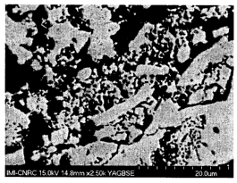
Fig. 3A is a photomicrograph showing a microstructure (cross-section)
of a zirconia-yttria nanostructured coating in accordance with an embodiment
of the invention;
Fig. 3B is a magnified view of a darker region in Fig. 3A;
Fig. 3C is a magnified view of Fig. 3B showing the porous
nanostructured inclusion in the darker regions;
Fig. 4 is a photomicrograph showing a microstructure (cross-section) of
prior art high temperature abradable A2;
Fig. 5 is a photograph of a wear scar formed during an abradability test
(condition A) of nanostructured coating;
Fig. 6 is a photograph of a wear scar formed during an abradability test
(condition B) in the nanostructured coating;
Fig. 7 is a graph showing the effect of the thermal-treatment on thermal
diffusivity of nanostructured and conventional zirconia-yttria coatings;
7
CA 02648643 2008-10-17
WO 2007/121556 PCT/CA2007/000636
Figs. 8A,B,C are a photomicrograph images showing a microstructure
(cross-section) of a zirconia-yttria nanostructured coating (of Fig. 3) after
a
heat-treatment at 1400 C for 1 h, 5 h, and 20 h, respectively;
Fig. 9 is a magnified view of Fig. 8C demonstrating that the porous
nanostructured inclusion in the darker regions of Fig. 3 shrink (forming a
void
space) but do not fully densify after a thermal-treatment at 1400 C for 20 h;
and
Fig. 10 is a graph showing the effect and evolution of the heat-
treatment on the elastic modulus values of nanostructured (of Fig. 3 - in
accordance with an embodiment of the invention) and conventional zirconia-
yttria coatings.
Description of Preferred Embodiments
The present invention is directed to thermal sprayed ceramic
nanostructured coatings that have porous nanostructured inclusions uniformly
distributed throughout. By controlling feedstock and thermal spray parameters
Applicant has produced a distribution of the porous nanostructured inclusions
that results in nanostructured coatings that have desirable thermal, and
mechanical macroscopic characteristics. For example, controlling the
distribution of porous nanostructured inclusions further permits the abradable
coatings to be of a desired resistance to crumbling (fragmenting) permitting
application in harsh operating environments and permits control over
elasticity
modulus properties to permit low thermal stress interfaces with a TBC.
Thermal spray coatings according to the invention are produced from
agglomerated ceramic nanoparticles, which may be composed of any ceramic
nanoparticles that can be agglomerated into particles suitable for thermal
spray coating and provide the desired porosity. The ceramic nanoparticles
may be made of zirconium oxide, such as zirconium oxide stabilized by
another metal oxide. Zirconium oxide stabilized by yttrium oxide is
particularly
preferred. Yttrium oxide stabilized zirconium oxide has a general formula of
Zr02 - x wt% Y203, where x is preferably about 5-20 wt%, more preferably
about 6-8 wt%. Zirconium oxide may be alternatively stabilized by calcium
8
CA 02648643 2008-10-17
WO 2007/121556 PCT/CA2007/000636
oxide, or magnesium oxide, and may further comprise cerium oxide, titanium
oxide or other materials as stabilizers. Any of the zirconium oxides used may
have small amounts of different materials, for example, A1203, Si02 and
Dy203 (dysprosia).
The agglomerated ceramic nanoparticles are agglomerated to produce a
highly porous particle. Preferably the agglomerated ceramic nanoparticles form
a porosity network. The bond between the individual ceramic nanoparticles may
be rather weak.
Advantageously, the method can produce a nanostructured coating (e.g.
abradable coating or thermal barrier coating (TBC)) having .desired properties
entirely from a single agglomerated ceramic nanoparticles. Alternatively the
feedstock could include agglomerated ceramic nanoparticles and other
feedstock components.
The ceramic nanoparticles that form the agglomerated ceramic
nanoparticles preferably have an average size of from about 2 nm to about
400 nm, more preferably from about 4 nm to about 200 nm, and more
preferable still, from 30-130 nm.
It is known to agglomerate ceramic nanoparticles by the process of
spray-drying to form microscopic, spherical, porous, agglomerated ceramic
nanoparticles. Fortunately the spherical shape of the agglomerates is a
natural
product of the spray-drying process. The advantage of this shape is that
spheres have the highest volume to surface area ratio resulting in a highest
fraction of unmelted or partially melted core, and a most easily controlled
fraction of unmelted or partially melted to melted material. It will be
appreciated
that the roundness of the agglomerates is not as important as the porosity for
application in this invention.
The distribution of diameters of the agglomerated ceramic nanoparticles
used to make the feedstock may, for example, range from 5 pm to 200 pm. The
porous agglomerated particles may have a diameter distribution centered at
between 50 microns and 130 microns, more preferably between 80 and 120
microns and more preferably 90 to 110 microns. In general, higher diameters of
9
CA 02648643 2008-10-17
WO 2007/121556 PCT/CA2007/000636
the agglomerated ceramic nanoparticles permit greater density of the porous
nanostructured inclusions, but agglomerated ceramic nanoparticles of higher
diameters require higher power torches to provide a given deposition
efficiency.
The foregoing ranges are preferred ranges for zirconium oxide agglomerates,
when sprayed using a 35-45 KW plasma spray torch.
Mixtures (blends) of agglomerated ceramic nanoparticles and
conventional feedstock particles may also be used to engineer the feedstock to
impart known properties of the conventional feedstock particles to the
nanostructured coating, such as electrical, magnetic, mechanical, chemical or
thermal properties.
For producing abradable coatings, for example, different materials, such
as boron nitride (BN), may be added in the agglomerated ceramic nanoparticles
to further lower a coefficient of friction of the coating. Furthermore, the
addition
of a polymer, such as polyester to subsequently be burned out to produce
additional porosity in the material in accordance with the techniques known in
the art of thermal sprayed abradable coatings, can also be used.
Further examples of conventional feedstock powders that may be added
include particles having a lower melting point than that of the agglomerated
ceramic nanoparticles to improve deposition efficiency. Such powders may be
selected to minimize infiltration of liquid phase into the porous, non-molten
portion of the particles, for example, by choosing a particle that melts to
produce a high viscosity fluid.
The feedstock including the agglomerated ceramic nanoparticles may
potentially be deposited by any thermal spray device known in the art, for
example, using a plasma spray, a flame spray torch. Applicant has
successfully applied the coating using an air plasma torch.
Thermal spraying in a controlled manner using spray conditions that do
not fully melt the agglomerated ceramic nanoparticles, and preferably do not
encourage the molten part of the feedstock to infiltrate (via capillary
effect) into
the network of porosity of the non-molten portion of the particles (porous
nanostructured inclusions) is preferred. This may be accomplished by using
CA 02648643 2008-10-17
WO 2007/121556 PCT/CA2007/000636
agglomerated ceramic nanoparticles having relatively large diameters, and
imparting a relatively high velocity to the feedstock such that the feedstock
has
a relatively short dwell time in the plume of the spray torch. The
agglomerated
ceramic nanoparticles, when deposited, retain unmelted or semi-molten porous
cores, resulting in the porous nanostructured inclusions distributed within
the
coating. They become features of the coating microstructure that can be
readily
identified by cross-section imaging. Therefore, in addition to the voids that
are
normally observed in thermally sprayed materials, i.e. coarse pores (formed by
the imperfect packing of thermally sprayed particles), and fines pores
(located
in between two adjacent thermal spray splats), this type of coating exhibits
porous nanostructured inclusions that contain a third and new type (or source)
of porosity.
It is thought that this extra source of porosity will lower even further the
thermal diffusivity, thermal conductivity and elastic modulus values of these
top
coats, as is advantageous for forming a more efficient, and longer lasting
TBC.
This unique structure may allow this coating to operate at temperatures higher
than those of current TBCs. Furthermore, the uniformity and density of the
distribution of porosities throughout the coating microstructure (both across
the
sprayed surface and throughout the depth of the coating) imparts a desirable
level of friability to an abradable coating, for example.
Also, the porous nanostructured inclusions embedded in the
nanostructured coating microstructure act as "weak links" for the
nanostructured coating making them useful as abradable coatings. During the
rubbing of a turbine blade against this type of nanostructured coating, as the
porous nanostructured inclusions lower the coating's strength and integrity,
the
nanostructured coating is easily removed, avoiding major blade wear and
consequently forming the seal, or abradable coating.
The nanostructured coating microstructure preferably comprises an
amount of about 10-80% by volume of porous nanostructured inclusions, more
preferably about 20-45% by area, based on total area of the nanostructured
coating (cross-section). Amounts in a range of 30-35% by volume may be
particularly readily produced. The amount of porous nanostructured inclusions
11
CA 02648643 2008-10-17
WO 2007/121556
PCT/CA2007/000636
may be conveniently measured by visual image analysis. Porosity of the
nanostructured coating is generally reasonably good, a porosity of 10-50% (as
measured by visual image analysis) being typical, although higher porosities
may be attainable.
Thermal spraying is a generally known technique in the art. In the
present invention, the feedstock of ceramic material is preferably thermally
sprayed at a temperature around the average melting point of the ceramic
material, for example at a temperature of 400 C of the average melting point
of the ceramic material. A temperature range of 200 C of the average
melting point may be particularly preferred. In general the better control
over
the temperature, the more effectively the distribution and uniformity of the
porous inclusions can be controlled. Spraying at lower temperatures
encourages the formation of more particulate phase in the coating
microstructure (i.e., less particle melting) resulting in a coating with
higher
amounts of semi-molten particles or higher porosity. However, spraying at
temperatures that are too low reduces coating deposition efficiency (i.e. the
ratio of feedstock particles that adhere to the surface to those that bounce
off
the substrate and do not adhere).
During thermal spraying, the ceramic material is preferably sprayed at
a velocity of about 50-600 m/s. Velocities in a range of about 150-400 m/s
may be particularly desirable. Velocities in a range of about 200-250 m/s are
particularly useful in the thermal spray of zirconium oxide-based
agglomerated ceramic nanoparticles having a morphology and size as
described herein.
First Example, Abradable coating
Feedstock Powders and Thermal Spraying:
Ceramic abradable coatings (A1), as exemplary embodiments of the
invention, were formed from zirconia-yttria (Zr02-7wt% Y203) (NanoxTM
S4007, Inframat Corp, Farmington, CT, USA) agglomerated ceramic
nanoparticles. The microscopic agglomerates exhibited diameters varying
12
CA 02648643 2014-05-20
from -10 to 160 pm. Each microscopic agglomerate was formed by the
agglomeration of individual nanosized zirconia-yttria particles via the spray-
drying process. Sieving was employed to remove smaller NanOXTM S4007
agglomerates from the initial size distribution to produce a distribution as
shown in Fig. 1. The 10-160 pm powder was sieved using a 53 pm (Mesh
270) USA Standard Testing Sieve, in an Alpine Augsburg Vacuum Sifter
(Germany) in to order to try to obtain a particle size range of approximately
53-160 pm. Portions of 50 g of powder were sieved for 5 minutes each to
produce the desirable particle size distribution, until the desired quantity
of
powder had been obtained. The diameter distribution of particles used in the
feedstock is centered near 90 pm, and is 80% contained between 61 and 119
m. It was confirmed that this feedstock has strong nanostructural
characteristics (individual nanosized particles varying from -30 to -130 nm)
and high porosity (Fig. 2).
A high temperature, metal-based, abradable coating (A2) (CoNiCrAIY-
BN-polyester) (SulzerTm Metco 2043, Sulzer Tm Metco, Westbury, NY, USA)
was employed to serve as a reference for comparison with the ceramic
abradable. Feedstock powders were thermally sprayed by using an air plasma
spray torch (F4-MB, SulzerTm Metco, Westbury, NY, USA). Both coatings
were deposited on HastelloyTM X substrates that had been grit-blasted to
roughen the surface before spraying.
Prior to deposition, plasma spray velocities and temperatures of the
zirconia-yttria particles (for A1) in the spray jet were measured using a
diagnostic tool (DPV 2000, Tecnar Automation, Saint Bruno, QC, Canada).
The diagnostic tool is based on optical pyrometry and time-of-flight
measurements to measure the distribution of particle temperature and velocity
in the thermal spray jet. A total of 5000 particles were measured at the
centerline of the thermal spray jet, where the particle flow density was the
highest. The particle detector was placed at the same spray distance as used
when depositing the coatings, i.e., 10 cm from the torch nozzle.
13
CA 02648643 2014-05-20
During the spraying process, a cooling system (air jets) was applied to
reduce the coating temperature, which was monitored using a pyrometer. The
maximum surface temperature was approximately 160 C for the A1 coatings
and 150 C for the A2 coating. The thicknesses of the coatings varied from 2.3
to 2.5 mm. Two different sets of spray parameters were used to spray the A1
coatings (producing two different coatings: A1-1, A1-2), whereas, one set of
spray parameters was employed to spray the A2 coating.
For the A1 coatings, a -175 pm thick CoNiCrAlY bond coat (Amdry
9951, SulzerTM Metco, Westbury, NY, USA) had been previously deposited
with a air plasma spray (F4-MB, SulzerTM Metco, Westbury, NY, USA) on the
HastelloyTM X substrates after the grit blasting, as usually done for thermal
spray coatings to roughen and promote the mechanical anchoring (adhesion)
of the sprayed particles onto the substrate surface.
Heat Treatment for Reference Sample:
The polyester of the feedstock used to form A2 was burned out of the
coating (to create porosity) by using the following conditions supplied by
SUIZerTM Metco: (i) ramping up from room temperature to 500 C at 5 C/min,
(ii) soaking at 500 C for 3.5 hours and (iii) ramping down from 500 C to room
temperature in approximately 2 hours.
Nano and Microstructural Characterizations:
Nanostructural and microstructural features of the agglomerated
ceramic nanoparticles feedstock and coatings were evaluated via scanning
electron microscopy (SEM). The porosity of the coatings was measured by
image analysis. A total of 10 images per coating were evaluated for porosity
measurements. The percentage of porous nanostructured inclusion in the
microstructures of the coatings was also measured via image analysis. A total
of 10 images per coating were evaluated for the determination of the
percentage of cross-section area of the porous nanostructured inclusions.
14
CA 02648643 2008-10-17
WO 2007/121556 PCT/CA2007/000636
Coating Macroscopic Hardness:
The hardness of the coatings was measured on a HR15Y scale with a
12.7 mm (0.5") WC ball under a 15 kgf load. A total of 5 measurements were
taken for each coating.
Rub-Rig Test
Abradability tests were carried out using a rub-rig, which can simulate
operating conditions of typical gas turbine engines. All tests were performed
at room temperature according to the conditions described in Table 1. The
rub-rig tests were performed under different blade tip speeds and seal
incursion rates. (conditions A and B) simulating operating conditions of gas
turbines. Two tests per condition were evaluated for each coating examined.
After rub-rig testing, the volume loss of each coating was measured via
optical profilometry. The blade wear was measured by a digital vernier caliper
while the seal wear was determined using a dial indicator mounted on a
height gauge. During rub-rig testing, a pyrometer (400-1400 C temperature
measuring range) was employed to measure the surface temperature of all
abradable coatings tested. As the pyrometer did not register any temperature
signal for all tests, it is assumed that the surface temperature for all
coatings
during rub-rig testing was below 400 C. The rub-rig and facility details can
be
found in Table 2.
Table 1
Rub-Rig Test Conditions for Abradability Evaluations*
Condition A B
Blade tip speed (m/s) 310 155
Incursion rate (m/s) 2.5 760
Total incursion (mm) 1 1
Blade material Inconel 718TM Inconel 718TM
(blade width: 6 mm ¨ blade thickness: 3 mm)
15
CA 02648643 2008-10-17
WO 2007/121556
PCT/CA2007/000636
Table 2
Rub-Rig and Facility Details
Air turbine performance At 250 SCFM, 150 psig - 8 Hp, 12 in-
lbs torque, 40,000 rpm
Tip speed 425 m/s
Pyrometer 400-
1400 C temperature measuring
range
Horizontal load cell 50 lbs capacity
Vertical load cell 25 lbs capacity
Radial incursion 2.5 pm/s to 760 pm/s
Axial incursion 5 pm/s to 760 pm/s
Heated tests Up to 760 C (flat samples)
Data acquisition system Acquisition rates up to 25 Hz
Nanostructure of the Zirconia-Yttria Feedstock
Referring to Fig. 2A and Fig. 2B, a typical zirconia-yttria particle is
shown. When analyzed at higher magnification (Fig. 2B) it is possible to
observe the nanostructured features of the feedstock. Each microscopic
feedstock particle was agglomerated by spray-drying of zirconia-yttria
nanoparticles, with diameters varying from -30 to -130 nm. Therefore it is
confirmed that this feedstock exhibited a strong nanostructural character and
was porous.
Particle Temperature and Velocity
Average values (and standard deviations) of surface temperature and
velocity of the particles in the spray jet for the A1-1 coatings were 2666
195 C and 244 65 m/s, respectively. Surface temperatures and velocities in
16
CA 02648643 2008-10-17
WO 2007/121556 PCT/CA2007/000636
the spray jet for the A1-2 coatings were 2563 174 C and 208 50 m/s,
respectively. As the melting point of Zr02-7wV/0 Y203 is approximately
2700 C, not all particles were fully melted during spraying, i.e., semi-molten
particles were also deposited in addition to the fully molten ones. Therefore
the original porous nanostructure of the feedstock remained in parts of the
coating microstructure, as discussed below.
Microstructural Characterization:
The overall microstructure of coating A1-2 is depicted in Fig. 3A. It is
evident that the coatings have a bimodal microstructure represented by lighter
. and darker regions. When the darker regions are observed at higher
magnifications, semi-molten zirconia-yttria nanoparticles are evident (Figs.
3B,C). The amount of semi-molten zirconia-yttria nanoparticles embedded in
the nanostructured coating for A1-1 and A1-2 were found to be 30 2% and
35 3%, respectively, based on total surface area of a cross-section of the
coating.
It is evident from the structure of an agglomerate of ceramic
nanoparticles (Fig. 2B) that its mechanical integrity is weak. The agglomerate
of ceramic nanoparticles is very porous and tiny necks hold the clusters of
individual ceramic nanoparticles together. Therefore, if a large quantity of
these agglomerated ceramic nanoparticles, in a semi-molten state, are
embedded in the nanostructured coating, they will act as weak links for
coating integrity. Consequently, this type of coating may be friable, even
though it is composed entirely of a ceramic.
The microstructure of the A2 coating is shown in Fig. 4. It is evident
that that the A2 coating was highly porous, which is necessary to lower the
mechanical integrity of the coating in order to increase its abradability
properties.
The porosity values for all three coatings evaluated are listed in Table
3. It is important to note that the porosity of A2 is higher than the porosity
standardized by the manufacturer (Sulzer Metco), which is 35-45%. Thus A2
17
CA 02648643 2014-05-20
as measured is nearly twice as porous as that standardized by the
manufacturer. The high porosity values are believed to be the result of non-
optimized spray parameters.
Table 3
Porosity values measured by image analysis
Coating Porosity % (n=10)
A1-1 Nano zirconia-yttria 15 + 1
A1-2 Nano zirconia-yttria 20 1
A2 CoNiCrAIY+BN+polyester 70 + 3
The feedstock of A1-1 was sprayed at higher values of particle
temperature and velocity than those of A1-2. As a consequence, A1-1
exhibited lower amounts of non-molten particles and lower porosity than A1-2,
illustrating that feedstock sprayed at lower temperatures and lower velocities
leads to more porous coatings.
Coating Hardness:
Values of Rockwell Y hardness of the coatings are listed in Table 4. It
is evident that the A1 coatings are much harder than A2. In fact, the A1
coatings are, on average, 4 times harder than the metallic-based abradable.
Table 4
Rockwell Y hardness measured with 12.7 mm (0.5") WC ball under 15 kgf
load
Coating HR15Y (n=5)
A1-1 Nano zirconia-yttria 87 1
A1-2 Nano zirconia-yttria 78 2
A2 CoNiCrAIY+BN+polyester 20 + 4
The hardness of the A2 coating is about three times lower than the
hardness standardized by the manufacturer (SulzerTM Metco), which is 60-70.
The low hardness value like the high porosity are believed to be the result of
non-optimized spray parameters. The A2 sample is just used for a "ballpark"
18
CA 02648643 2014-05-20
comparison or relative reference. As it is softer than a regular abradable, it
is
thought that if this sample were harder, the performance of the A-1 coatings
during rub-rig testing would stand out even more.
Rub-Rig Testing Results:
Rub-rig test results for condition A are listed in Table 5. Condition A
represents the test carried out at high blade speed and slow blade incursion.
Under these conditions all coatings behaved in a similar way, i.e., there were
no significant differences among blade wear, seal wear and volume loss for all
the coatings. The blade was virtually intact for all tests.
Table 5
Rub-rig test results for condition A (two tests per condition per coating)*
Coating Blade wear Seal wear Volume
loss
(Lim) (1-tm) (mm3)
A1-1 Nano zirconia-yttria 0 1003 129
A1-1 Nano zirconia-yttria 0 965 120
A1-2 Nano zirconia-yttria 0 1041 137
A1-2 Nano zirconia-yttria 13 978 126
A2 CoNiCrAIY+BN+polyester 0 965 129
A2 CoNiCrAIY+BN+polyester 0 973 132
A1 coatings did not shatter or chip during the abradability test. Fig. 5 is
a photograph of the wear scar of the nanostructured coating sprayed using
A1-2. It shows a well-defined and smooth structure. Metallic residues from the
metallic blade are not visually apparent. Therefore, this coating is very
friable
for this test condition.
Rub-rig test results for condition B are listed in Table 6. Condition B
represents the test carried out at low blade speed and fast blade incursion.
19
CA 02648643 2008-10-17
WO 2007/121556
PCT/CA2007/000636
Table 6
Rub-rig test results for condition B (two tests per condition per coating)*
Coati nci Blade wear Seal wear Volume
loss
(iim) (Pm) (mm3)
A1-1 Nano zirconia-yttria 373 622 60
A1-1 Nano zirconia-yttria 381 546 136
A1-2 Nano zirconia-yttria 183 732 76
A1-2 Nano zirconia-yttria 102 762 83
A2 CoNiCrAIY+BN+polyester 0 948 125
A2 CoNiCrA1Y+BN+polyester 0 957 140
Under these conditions, A2 exhibited the best performance, i.e., it
exhibited the lowest blade wear and highest seal wear and volume loss. The
A1-1 coating exhibited the lowest abradability, with the highest blade wear
and lowest seal wear and volume loss. A1-1 was (i) sprayed with the highest
particle velocity and temperature values, (ii) exhibited the lowest amount of
non-molten particles embedded in the coating microstructure, (iii) the highest
hardness and (iv) the lowest porosity.
However, it must also be stressed that the A2 coatings tested as
comparative examples herein contained a much higher level of porosity and
were much softer than the metallic-based coatings normally employed in the
art. The expected hardness is 60-70, and not 20 as measured. Therefore, it is
expected that the differences in wear performance between ceramic coatings
of the present invention and the metallic-based coatings normally employed in
the art would be greatly reduced for the metallic-based coatings produced
using optimized conditions.
The A1 coatings, despite being not as friable as the metallic-based
abradable, exhibited good performance, especially under test condition A.
The A1 coatings did not shatter or chip during the abradability test. The wear
scars of these coatings are also well-defined, however, metallic residues of
CA 02648643 2008-10-17
WO 2007/121556 PCT/CA2007/000636
the metallic blades on their surfaces can be observed (Fig. 6). On the other
hand, the wear scars of the A2 coating were not as smooth as those of the
ceramic seal.
Conclusion:
Despite ceramic being generally considered to be hard and stiff, a
nanostructured ceramic material can be employed to form abradable coatings
with friable structures. By thermal spraying porous agglomerated ceramic
nanoparticles such that the feedstock does not completely melt or infiltrate
the porosity network of the agglomerated ceramic nanoparticles, ceramic
nanostructured coatings with very high friability can be formed by uniformly
distributing a relatively high concentration of porous nanostructured
inclusions
in the coating microstructure.
Under abradability testing using high blade speed and slow blade
incursion, there are no significant differences in performance between the
nanostructured ceramic A1 and the metallic-based abradable coatings A2,
despite the nanostructured ceramic coatings being 4 times harder than the
metallic-based abradable.
Under abradability testing using low blade speed and fast blade
incursion, the A2 coating exhibited better performance, however, by
increasing the volume of non-molten nanostructured ceramic particles
embedded in the coating microstructure, it is expected that the ceramic
abradables may perform like the metallic abradable under these test
conditions.
During all abradability tests, the two ceramic abradables exhibited
uniform wear scars without chipping or shattering.
Second example; TBC
Feedstock Powders and Thermal Spraying:
A ceramic B1 as an embodiment of the invention useful as a top coat
of a TBC was formed from agglomerated ceramic nanoparticles (Zr02-7wt%
21
CA 02648643 2014-05-20
Y203) Powder (NanoxTM S4007, lnframat Corporation, Farmington, CT, USA).
The nanostructured feedstock powder was thermally sprayed by using an
Ar/H2 air plasma spray torch (F4-MB, SUIZerTM Metco, Westbury, NY, USA).
The microscopic agglomerates exhibited diameters varying from -10 to 160
pm. Each microscopic agglomerate was formed by the agglomeration of
individual nanosized zirconia-yttria particles via the spray-drying process.
Sieving was employed to remove smaller NanOXTM S4007 agglomerates from
the initial size distribution to produce a distribution centered substantially
shown in Fig. 1. The 10-160 pm powder was sieved using a 53 pm (Mesh
270) USA Standard Testing Sieve, in an Alpine Augsburg Vacuum Sifter
(Germany) in to order to try to obtain a particle size range of approximately
53-160 pm. Portions of 50 g of powder were sieved for 5 minutes each to
produce the desirable particle size distribution, until the desired quantity
of
powder had been obtained. The diameter distribution of particles used in the
feedstock is centered near 90 rn, and is 80% contained between 61 and 119
gm. It was confirmed that this feedstock has strong nanostructural
characteristics (individual nanosized particles varying from -30 to -130 nm)
and high porosity (Fig. 2).
For comparison, a conventional top coat B2, representing a widely
known top coat currently applied by turbine industries, was deposited from a
conventional (i.e. non-porous) zirconia-yttria (Zr02-8wt% Y203) powder
(Metco 204B-NS, SulzerTM Metco, Westbury, NY, USA) using an Ar/H2 air
plasma spray torch (9-MB (GH nozzle), Sulzer Tm Metco, Westbury, NY, USA).
Coatings were deposited on metallic substrates (low carbon steel) that had
been grit-blasted to roughen the surface before spraying.
Before deposition of the coating, velocities and temperatures of the
zirconia-yttria agglomerated ceramic nanoparticles in the plasma spray jet
were measured using a diagnostic tool for both the nanostructured and
conventional feedstock (Accuraspray, Tecnar Automation, Saint Bruno, QC,
Canada). The diagnostic tool is based on optical pyrometry and time-of-flight
measurements to measure the distribution of particle temperature and velocity
in the thermal spray jet. The particle detector was placed at the same
22
CA 02648643 2008-10-17
WO 2007/121556 PCT/CA2007/000636
spray distance as used when depositing the coatings, i.e., 10 cm and 11 cm
from the torch nozzle for the nanostructured and conventional powders,
respectively.
During the spraying process, a cooling system (air jets) was applied to
reduce the coating temperature, which was monitored using a pyrometer. The
maximum surface temperature was approximately 160 C for the zirconia-yttria
coatings. The thicknesses of the coatings were about ¨500 pm.
Nano and Microstructural Characterizations:
Nanostructural and microstructural features of the feedstock and
nanostructured coating coatings were evaluated via scanning electron
microscopy (SEM). The porosity of both the coatings was measured via
image analysis. A total of 10 images per coating were evaluated for porosity
measurements. The percentage of non-molten zirconia-yttria agglomerated
ceramic nanoparticles embedded in the nanostructured coating was also
measured via image analysis, by manually selecting the non-molten
inclusions. A total of 10 images per coating were evaluated for the
determination of the percentage of non-molten particles.
Thermal Treatment
A thermal treatment (-tt) was performed on B1-tt and B2-tt coatings to
determine the effect of temperature on the microstructure, thermal diffusivity
and elastic modulus values. The thermal treatment was carried out on free-
standing coatings that had been removed from the low carbon steel
substrates by dissolving the metal base. The thermal treatment was carried
out in a furnace in air by commencing at room temperature and increasing to
1400 C over a 60-90 min. period. The coatings were left at this temperature
for a dwell time of 1, 5 and 20 h. After each period, the samples were
removed from the furnace and allowed to cool. Initial cooling was very rapid
and, typically, room temperature was reached within 30 min.
Thermal Diffusivity
23
CA 02648643 2008-10-17
WO 2007/121556 PCT/CA2007/000636
The thermal diffusivity of as-sprayed and thermally treated coatings
was determined by a laser flash method. The measurements were made on
coatings that had been removed from the substrate.
Particle Temperature and Velocity
Average values of surface temperature and velocity were 2670 C and
210 m/s for the agglomerated ceramic nanoparticles and 2700 C and 148 m/s
for the conventional powder. As the melting point of Zr02-7-8wV/0 Y203 is
about 2700 C, not all particles were fully molten during spraying, i.e., semi-
molten particles were deposited in addition to the molten ones. Therefore,
core parts of the original agglomerated ceramic nanoparticles of the feedstock
were embedded in the coating microstructure, as discussed below.
Microstructure of the nanostructured coating
The nanostructured coating coating shown in Figs. 3A-C is
representative of the as-sprayed coatings B1 produced by the present
example. It is evident that the coating exhibits a bimodal microstructure
formed by lighter and darker regions. When the darker regions are observed
at higher magnifications, semi-molten agglomerates, resulting from the partial
melting of the feedstock particles, are evident (Fig. 3B,C). This
characteristic
arises when the molten part of a semi-molten particle does not fully penetrate
into its non-molten inner core. The amount of non-molten agglomerates
embedded in the coating microstructure was about 35% (based on total
surface area of a cross-section of the coating).
It is evident from the microstructure of typical agglomerates (Fig. 2A,B)
that they are very porous, and tiny necks hold the clusters of individual 30-
130 nm particles together. Therefore, if a large quantity of these particles,
in a
semi-molten state, is embedded in the coating microstructure, the overall
porosity of the coating will be substantially increased.
24
CA 02648643 2008-10-17
WO 2007/121556 PCT/CA2007/000636
Thermal Diffusivity
Figure 7 shows the results of thermal diffusivity at room temperature
for as-sprayed (i.e., non thermal-treated - ntt) agglomerated nanostructured
(B1-ntt) and conventional zirconia-yttria (B2-ntt) coatings and following
thermal treatment (-tt) (B1-tt,B2-tt) at 1400 C for 1, 5 and 20 h.
The thermal diffusivity of B2-ntt was 57% higher than that of B1-ntt.
The thermal diffusivity of B2-tt coating was 59% higher than B1-tt after 20 h
of
thermal exposure. Therefore, the expected sintering effects of high
temperature exposure on the nanostructured coating did not appreciably
change the difference of thermal diffusivity between the two coatings. This
phenomenon is counter-intuitive, because according to conventional wisdom
in the art nanoparticles of ceramic exhibit higher sintering rates than those
of
conventional ones. This counter-intuitive phenomenon can be explained
based on the following observations (Fig. 8).
Figure 8 shows the cross-section of B1, after the heat treatment at
1400 C for 1 (Fig. 8A), 5 (Fig. 8B) and 20 h (Fig. 8C). By looking at these
pictures it is possible to observe that the porosity levels of this ceramic
coating increase with sintering time. While not being limited to the following
theory in all aspects of the invention, Applicant believes this counter-
intuitive
phenomenon can be explained by the partial sintering of the semi-molten
porous nanostructured inclusions. These semi-molten porous nanostructured
inclusions tend to sinter at higher rates than those of the "scaffold" of the
coating formed by previously fully molten and resolidified particles, due to
the
nanostructural character of the inclusions and high temperature effects
(1400 C), and therefore they tend to shrink at higher rates than than those of
the "scaffold".
As previously described, the porous nanostructured inclusions are
surrounded by dense resolidified particles (splats/lamellas, i.e., the
scaffold)
that were fully molten in the spray jet. These resolidified particles form
shells
that surround the semi-molten particles, thereby keeping coating integrity.
CA 02648643 2008-10-17
WO 2007/121556 PCT/CA2007/000636
These dense resolidified particles, due to their morphology and higher density
levels, should exhibit lower sintering rates than those exhibited by the
porous
nanostructured inclusions. As a consequence, the porous nanostructured
inclusions, during heat treatment, exhibit higher shrinkage rates than those
of
the resolidified lamellar structure (scaffold). Consequently, voids are
created
within the "shells" during heat treatment within the porous nanostructured
inclusions, as observed in Fig. 8.
This void creating characteristic is the counter-intuitive phenomenon,
which apparently keeps the thermal diffusivity levels of the ceramic coating
at
lower levels than those of the conventional one even after 20 h of heat
treatment at 1400 C.
It is important to point out that the heat treatment carried out did not
completely densify the inner structure of the porous nanostructured
inclusions. Figure 9 shows a higher magnification view of the coating
previously shown in Fig. 8C, which was heat treated at 1400 C for 20 h. Even
after the heat treatment it is possible to distinguish the porous
nanostructured
inclusions. The porous nanostructured inclusions that remain help to reduce
the thermal diffusivity levels of the ceramic coating, in addition to the
interlamellar voids created during heat treatment, also observed in Fig. 9.
Elastic Modulus
The elastic modulus values of the as-sprayed (non thermal-treated -ntt)
and thermal-treated (-tt) nanostructured B1 and conventional B2 coatings
were also measured (Fig. 10). The elastic modulus values were measured by
laser-ultrasonics.
The elastic modulus values of B2-ntt was higher than that of B1-ntt.
The heat treatment did not alter this observation. The elastic modulus value
of B2-tt was 290% higher than B1-tt after 20 h of thermal exposure at 1400 C.
26
CA 02648643 2008-10-17
WO 2007/121556
PCT/CA2007/000636
Given the dictates of conventional wisdom, it was important to verify
these properties of B1. As ceramic coatings (especially nanostructured
coatings) are subject to sintering effects that could abruptly increase the
stiffness of the material, (i.e., its elastic modulus) lowering its capacity
to
withstand thermal shocks and variations of shape (volume) that occur when
the coating material and its metallic substrate are heated from ambient
temperature to operational temperatures (or vice-versa), which can be higher
than 1000 C in gas turbines.
The low values of elastic modulus measured for the B1-ntt and B1-tt
coatings are also attributed to the same phenomenon that impeded significant
thermal diffusivity increase of this coating, as previously explained. This
counter-intuitive characteristic is not only important for the use of this
coating
as a TBC, but also as a high temperature abradable. These low elastic
modulus values may facilitate thicker TBCs with coatings of (e.g., 1 mm) of
this material.
It is important to point out that according to conventional wisdom, this
type of nanostructured coating would exhibit higher sintering effects (when
compared to those of conventional materials) in shorter amount of times
when exposed to same high temperature levels, such as, porosity healing and
increasing of stiffness (elastic modulus), due to the known enhanced sintering
effects caused by the nanoparticles within the porous nanostructured
inclusions.
According to conventional wisdom these enhanced sintering effects
would tend to increase the thermal diffusivity and elastic modulus values of
the nanostructured coating to higher values than those of the conventional
ceramic coating. However, by looking at Figs. 7 and 10 it is observed that the
thermal diffusivity and elastic modulus values of the nanostructured coatings
tend to stabilize after just 5 h of heat treatment at 1400 C, on the other
hand,
even after 20 h of heat exposure, the values of these two properties have not
shown signs of stabilization in the conventional coating. The results for the
27
CA 02648643 2008-10-17
WO 2007/121556 PCT/CA2007/000636
conventional coating show that sintering of the zirconia-yttria material is an
ongoing process even after 20 h at 1400 C.
The fact that the thermal diffusivity and elastic modulus values of the
B1 coatings tend to stabilize after just 5 h of heat exposure at 1400 C
demonstrates that B1 can be considered a so-called "intelligent material",
which has an internal mechanism for counteracting the influences of the
environment. Traditional materials are normally inert or reactive to the
environment in which they operate. Reactive materials generally lose their
performance and/or stability by reacting with the environment. For example,
materials that are attacked by corrosion.
The nanostructured coatings developed in this study appear to react
intelligently to a high temperature environment and react so that differential
sintering rates prevent steep continuous growth of thermal diffusivity and
elastic modulus values over time. As previously described, the partial
densification of the porous nanostructured inclusions (a sintering effect)
will
lead to void formation within the shells composed of previously fully molten
material that surround the porous nanostructured inclusions (Fig. 2). These
results are demonstrated in Figs. 7, 8, 9 and 10. It is important to point out
that the scale bars in Figs. 2A and 8 are parallel to the substrate surface.
Therefore, formation of these voids parallel to the substrate surface (Fig.
8),
will counter-act the sintering (densification) effects of the porous
nanostructured inclusions. In other words, the sintering (densification) of
the
porous nanostructured inclusions causes a compensation effect, i.e., the
formation of horizontal voids (in relation to the substrate surface). The void
formation parallel to the substrate surface will tend to lower (i) the heat
transfer that goes through thickness, from the environment to the substrate
and (ii) the elastic modulus values of the coatings. As an average balance
between sintering effects and void formation, these nanostructured coatings
will tend to exhibit rapid stabilization of thermal diffusivity and elastic
modulus
values after a few hours of thermal exposure at high temperatures.
28
CA 02648643 2008-10-17
WO 2007/121556
PCT/CA2007/000636
Conclusions
Agglomerated ceramic nanoparticles were thermally sprayed under
carefully controlled temperature and velocity conditions, which allowed the
engineering of zirconia-yttria nanostructured coatings containing 35% in area
of (porous nanostructured inclusions) distributed uniformly throughout the
nanostructured coatings.
The agglomerated ceramic nanoparticles are highly porous. The
porous nanostructured inclusions contain non-molten porous cores of the
agglomerated ceramic nanoparticles that are embedded in the microstructure
of the nanostructured coatings where the molten part of the feedstock did not
fully penetrate into the non-molten porous core.
The porous nanostructured inclusions are an additional source of
porosity within the nanostructured coating. This extra source of porosity
helps
to lower the thermal diffusivity values of zirconia-yttria coatings to levels
not
attained by regular conventional zirconia-yttria thermal spray coatings. The
presence of the porous nanostructured inclusions in the nanostructured
coating also lowers the elastic modulus of the nanostructured coatings,
rendering a coating with lower stiffness.
Heat treatment at 1400 C for 1, 5 and 20 h demonstrated that the
nanostructured zirconia-yttria coating exhibited significantly lower values of
thermal diffusivity and elastic modulus after 20 h exposure, when compared
to those of the conventional zirconia-yttria coating. These phenomena defy
conventional wisdom and may be explained based on the partial sintering of
the porous nanostructured inclusions, which are surrounded (as a shell) by
previously fully molten feedstock that resolidified on the surface during
coating formation. The porous nanostructured inclusions partially sinter and
shrink, leaving empty voids within the "shells" in the coating structure.
Therefore this type of coating may be considered as an "intelligent material",
which reacts in an intelligent way to the influences of the environment.
29
CA 02648643 2008-10-17
WO 2007/121556
PCT/CA2007/000636
These improved properties make it possible to create a more efficient
and reliable ceramic top coat as compared to currently used TBCs. Moreover,
this type of coating could be used as an intermediate layer between a base
coat and a top coat made of a ceramic material more stable at high
temperature.
Other advantages inherent to the structure are obvious to one skilled in
the art. It will be understood that certain features and sub-combinations are
of
utility and may be employed without reference to other features and sub-
combinations. This is contemplated by and is within the scope of the claims.
Since many possible embodiments may be made of the invention without
departing from the scope thereof, it is to be understood that all matter
herein
set forth or shown in the accompanying drawings is to be interpreted as
illustrative and not in a limiting sense.