Note: Descriptions are shown in the official language in which they were submitted.
CA 02648753 2008-10-17
WO 2007/121569 PCT/CA2007/000673
SOLID-STATE LIGHTING NETWORK AND PROTOCOL
FIELD OF THE INVENTION
[0001] The present invention pertains to the field of lighting and in
particular to the
control of lighting networks.
BACKGROUND
[0002] Two lighting network interconnect systems which are widely used today
are
DMX512A and the Digital Addressable Lighting Interface (DALI). DMX512 was
developed in the 1980s for control of stage lighting and DALI was developed in
the
1990s for fluorescent lamp control. DMX512 uses RS-485 and DALI operates on
proprietary hardware. Lighting technology, however, has progressed
tremendously over
the past decade and neither of these two interconnect systems easily
facilitates general-
purpose lighting control at a level desirable for solid-state lighting. Both
interconnect
systems are very closely tied to their hardware layer specifications, and,
while providing
flexible command definitions, are limited to a rigorous addressing and message
format.
[0003] Other interconnect systems rely on components from proprietary and open
technology. Widely known industry-standard interconnect systems are BACnet
(see
www.bacnet.org), BitBus (see www.bitbus.org), CANbus (see www.canbus.us), KNX
(see www.konnex.org), LonWorks (see www.longmark.org) ModBus (see
www.modbus.org) or X10 (see www.xl0.org), for example. These interconnect
systems
are well-suited for certain building or industrial site management
applications and even
for specialized home automation applications. They are feature rich and have
been used
with varying success to implement general lighting control networks but have
not been
found to provide cost effective solid-state lighting control interconnect
system solutions.
Remote control of solid-state lighting devices with existing general purpose
interconnect
systems is complicated and cost-ineffective.
[0004] One such system is described in the "BITBUSTM interconnect serial
control bus
specification", order number 280645-001 as published by Intel Corporation,
1988,
which is herein incorporated by reference. Interconnect systems have also been
CA 02648753 2008-10-17
WO 2007/121569 PCT/CA2007/000673
described in the patent literature.
[0005] For example, U.S. Patent No. 5,726,644 describes a lighting control
system
with packet hopping communication. The system can be used for building lights
that are
master controlled to reduce power consumption under building master control,
or in
response to electric utility commands to the building computer. Each lighting
wall
control unit includes a transceiver which can communicate to at least one
neighbour
transceiver, thereby forming a distributed communication network extending
back to the
building computer. The transceivers operate asynchronously with low data rate
FSK
signals, using carrier frequencies between 900 and 950 MHz. Different
communications
protocols control packet forwarding and acknowledgement so that messages reach
their
destination but are not forwarded in endless circles thereby potentially
reducing
collisions. This interconnect system, however, is configured to submit
commands for the
control of one parameter to all of the device control units.
[0006] U.S. Patent No. 6,175,771 describes a lighting communication
architecture
which provides different kinds of controlling options. A single channel per
line
communication is described, wherein this can be used to form single channel
DMX to
communicate with DMX format luminaires, while still using only one
communication
per line. The controlling console has a single connector that outputs
information for all
luminaires. This -is connected to a distribution rack, which itself includes
plural
connectors but spaced from the console. The multiple connectors can represent
communications in many different formats including formats of one lamp per
line, or
time division multiplexed formats of many lamps per line. The patent describes
interconnect architectures on a physical layer level but does not specify
instructions or
details of instruction encoding.
[0007] U.S. Patent Nos. 6,664,745, 6,570,348, 6,459,217 and 6,331,756 describe
methods and an apparatus for digital communications with multi-parameter light
fixtures. It is further described that a typical light fixture is an integral
unit that has a
lamp assembly and a communications node to control the lamp assembly and that
a
lighting system contain many such light fixtures. One type of lighting system
has at least
two communication systems that interconnect the light fixtures. A digital
controller is
connected to one of the communication systems, at least one of the light
fixtures of that
communication system is a designated gateway for sending control signals to
the other
2
CA 02648753 2008-10-17
WO 2007/121569 PCT/CA2007/000673
communication system. Another type of lighting system has two digital
controllers
connected to respective communication systems. Each of the communication
systems
interconnects many light fixtures, at least one of which has two communication
nodes
respectively connected to the communication systems. A third type of lighting
system
mixes the first and second types. These patents describe interconnect
architectures on a
physical layer level but do not specify instructions or details of instruction
encoding.
Thus there is a need for a new solid-state lighting interconnect system.
[0008] This background information is provided to reveal information believed
by the
applicant to be of possible relevance to the present invention. No admission
is
necessarily intended, nor should be construed, that any of the preceding
information
constitutes prior art against the present invention.
SUMMARY OF THE INVENTION
[0009] An object of the present invention is to provide a solid-state lighting
network and
protocol. In accordance with an aspect of the present invention, there is
provided a solid-
state lighting network comprising one or more master controllers and one or
more
nodes, and an interconnect system operatively coupling the one or more master
controllers to the one or more nodes, wherein the one or more nodes and the
one or more
master controllers are configured to generate messages and exchange the
messages via
the interconnect system, and wherein each message comprises a number of
parameters
and one of one or more command codes.
[0010] In accordance with another aspect of the present invention, there is
provided a
solid-state lighting network control method comprising generating messages,
with each
message comprising a number of parameters and one of one or more command
codes,
and communicating the messages via an interconnect system.
BRIEF DESCRIPTION OF THE FIGURES
[0011] Figure 1 illustrates a solid-state lighting network according to one
embodiment
of the present invention.
[0012] Figure 2 illustrates a table of commands for a solid-state lighting
interconnect
system according to an embodiment of the present invention.
3
CA 02648753 2008-10-17
WO 2007/121569 PCT/CA2007/000673
[0013] Figure 3A illustrates the first part of a table of commands for a solid-
state
lighting interconnect system according to an embodiment of the present
invention.
[0014] Figure 3B illustrates the second part of the table illustrated in
Figure 3A.
[0015] Figure 4 illustrates a table of commands for a solid-state lighting
interconnect
system according to an embodiment of the present invention.
[0016] Figure 5 illustrates a state machine for processing commands according
to one
embodiment of the present invention.
[0017] Figure 6 illustrates a state machine for processing transmitted
commands
according to one embodiment of the present invention.
DETAILED DESCRIPTION OF THE INVENTION
Definitions
[0018] The term "light-emitting element" (LEE) is used to define a device that
emits
radiation in a region or combination of regions of the electromagnetic
spectrum, for
example, the visible region, infrared or ultraviolet region, when activated by
applying a
potential difference across it or passing an electrical current through it.
Light-emitting
elements can have monochromatic, quasi-monochromatic, polychromatic or
broadband
spectral emission characteristics. Examples of light-emitting elements include
semiconductor, organic, or polymer/polymeric light-emitting diodes (LEDs),
optically
pumped phosphor coated LEDs, optically pumped nano-crystal LEDs or other
similar
devices as would be readily understood. Furthermore, the term light-emitting
element is
used to define the specific device that emits the radiation, for example a LED
die, and
can equally be used to define a combination of the specific device that emits
the
radiation together with a housing or package within which the specific device
or devices
are placed.
[0019] The term "solid-state lighting" is used to refer to a kind of lighting
that
employs electroluminescent light sources such as for example light-emitting
elements.
[0020] As used herein, the term "about" refers to a +/-10% variation from the
nominal
value. It is to be understood that such a variation is always included in any
given value
4
CA 02648753 2008-10-17
WO 2007/121569 PCT/CA2007/000673
provided herein, whether or not it is specifically referred to.
[0021] Unless defined otherwise, all technical and scientific terms used
herein have
the same meaning as commonly understood by one of ordinary skill in the art to
which
this invention belongs.
[0022] The present invention provides an interconnect system for controlling a
solid-
state lighting network. The lighting network comprises one or more master
controllers,
one or more nodes and an interconnect system. Tasks operate on both the master
controller and the nodes, which can be implemented in software or firmware,
which can
be processed by a computing device or processor associated with each thereof.
A master
control program can be operated within each master controller. The master
control
program comprises certain tasks which, based upon user input, generate and
control the
submission of messages via the interconnect system. The nodes can receive
messages
and tasks within the nodes can process the messages. Certain tasks within each
node can
respond to the received messages and may, depending on the type of the
message,
submit response messages back to the master controller(s) via the interconnect
system.
In this manner the message system can be used to implement commands of a solid-
state
lighting network protocol.
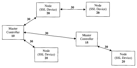
[0023] Figure 1 illustrates a lighting network according to one embodiment of
the
present invention. The lighting network comprises master controllers 10 and
15, which
via an interconnect system 30 are connected to one or more nodes 20, wherein
for this
embodiment each node is a solid-state lighting device. As illustrated, master
controller
10 can provide control messages over the interconnect system 30 to multiple
nodes and
optionally as illustrated to master controller 15. In addition, in some
embodiments of
the present invention, as illustrated in Figure 1, nodes can forward messages
therebetween also via the interconnect system.
[0024] Each message comprises a message code indicating whether the message is
a
command or a response to a command. Command messages can originate from the
master controller(s), whereas response messages can originate from nodes. The
data in
messages is controlled by tasks within a respective master controller or node.
[0025] Generally node tasks, i.e. tasks within a node, are intended to act
upon
commands encoded within messages received from the master controller(s) to
control
5
CA 02648753 2008-10-17
WO 2007/121569 PCT/CA2007/000673
the operating conditions of the node. Nodes can comprise lighting devices such
as
luminaires or fixtures which can comprise one or more solid-state or non-solid
state
lighting devices or actuators, for example. The operating conditions of a node
can
include luminous flux and chromaticity of emitted light generated by a
lighting device or
the orientation of the lighting device, for example.
Interconnect System
[0026] The unique requirements of solid-state lighting can be met by an
adequately
structured interconnect system of proper topology. The interconnect system can
support
a wired or wireless network, the configuration of which would be readily
understood by
a worker skilled in the art. The interconnect system provides a degree of
interconnectivity that is sufficient to be able to support exchange of
messages between
the master controller(s) and the nodes. The interconnect system may exchange
messages
directly between the master controller(s) and the nodes or some or all nodes
or master
controller(s) may relay messages to other nodes and master controllers.
[0027] In one embodiment of the present invention, the interconnect system can
be
fully interconnected such that each one of the nodes or master controller(s)
or both can
directly communicate with any one of the other nodes or master controller(s)
or both.
For example, nodes that utilize wireless networks are fully interconnected on
a physical
layer with all other nodes within the range of the respective carrier signals.
Wireless
networks according to the present invention can utilize different bands of
electromagnetic radiation such as visible, infrared, microwave or radio
frequencies. As
is well known, certain types of wired buses may also provide full
interconnectivity.
Wired networks can utilize any adequate cabling and topology.
[0028] In one embodiment of the present invention, the interconnect system
provides
interfaces for the connection of gateways for expansibility to other lighting
systems and
possible communication with either the same or another type of network. The
interconnect system can optionally comprise interfaces to other networks which
are not
exclusively dedicated to lighting control, for example, gateways to a building
management system or the like.
[0029] The present invention provides a solid-state lighting network
interconnect
system specified in accordance with the Open Systems Interconnection Reference
Model
6
CA 02648753 2008-10-17
WO 2007/121569 PCT/CA2007/000673
(OSI model) which is herein incorporated by reference. The OSI model utilizes
a
hierarchical description for communications and computer network protocol
design.
Detailed information about the OSI model is readily available and widely
known.
[0030] The OSI model describes interconnect systems in a seven layer
hierarchical
model: Layer 7, also called the application layer, specifies network
applications such as
file transfer, terminal emulation, email etc. Layer 6, also called the
presentation layer,
specifies how to represent or encode data. Layer 5, also called the session
layer, defines
how communication sessions are established between network devices. Layer 4,
also
called the transport layer, specifies data flow control, error correction and
data recovery.
Layer 3, also called the network layer, specifies how data is organized into
chunks or
packets and also defines address assignment and package forwarding. Layer 2,
also
called the data link layer, defines frame format and error checking. Layer 1,
also called
the physical layer, defines the physical implementation of the network
including the
medium, for example, wire or wireless, which is used for data exchange.
Solid-State Lighting Device
[0031] In one embodiment of the present invention, a node is a solid-state
lighting
device. Examples of solid-state lighting devices include solid-state
luminaires or
fixtures. A solid-state lighting device can comprise one or more light-
emitting elements
or a one or more groups of light-emitting elements, wherein each group can
comprise
one or more light-emitting elements. Each group can comprise light-emitting
elements
of the same nominal chromaticities, for example chromaticities can be in the
red, green,
blue, amber, purple or white range etc. When differently coloured light-
emitting
elements emit light which is adequately mixed, controlling colour and
intensity of the
mixed light is then a matter of controlling the amount of light provided by
each of the
same colour light-emitting elements. The colour of the mixed light can thus be
controlled within a range of colours defined by the colour gamut of the
illumination
device. The colour gamut is defined by the different colour light-emitting
elements
within the illumination device subject to achievable operating conditions.
[0032] Current drivers are coupled to the arrays and are configured to supply
current
to each array of light-emitting elements separately. The current drivers
control the
amount of drive current supplied to and hence the amount of light emitted by
the light-
7
CA 02648753 2008-10-17
WO 2007/121569 PCT/CA2007/000673
emitting elements. The current drivers are configured to regulate the supply
of current to
each array separately so as to control the luminous flux and chromaticity of
the
combined mixed light. A power supply coupled to the current drivers can
provide
electrical power.
[0033] A lighting device controller is coupled to current drivers and the
controller is
configured to independently adjust each average forward current by separately
adjusting
the duty cycles of each of current drivers. The controller transmits control
signals to
each of current drivers, wherein the control signals determine the current
generated by
the current drivers which is supplied to each array of light-emitting
elements. Variations
of the drive current, which are intended to control the time-averaged amount
of light
emitted by the light-emitting elements, are desirably fast enough to avoid
perceivable
flicker.
[0034] A solid-state lighting network protocol for the solid-state lighting
network
specifies how to control the operating conditions of the lighting devices in
the lighting
network. The message format defines how the lighting devices can be addressed.
Different embodiments of the present invention may address lighting devices in
different
ways.
[0035] In one embodiment for example, messages can include an address field.
The
address field can contain address data encoding an address referring to a
specific node.
One or more nodes in the network may share the same address. Alternatively, a
sequence
of multiplexed messages can be sent to all nodes on, for example, a bus, and
the position
of each message within the sequence determines what node the message is
designated
for. It is then up to the node to extract the right message(s) from the
sequence. Further,
certain network topologies permit the master controller(s) to communicate with
each one
of the nodes separately via a dedicated physical connection that is not shared
with other
nodes such as in a star topology, for example. Interconnect systems according
to the
present invention may therefore utilize different protocols which either
include or
exclude address data in the message format.
Lighting Device Controller
[0036] A lighting device comprises an internal lighting device controller. A
lighting
device controller can be a device having a programmable central processing
unit (CPU)
8
CA 02648753 2008-10-17
WO 2007/121569 PCT/CA2007/000673
(such as a microcontroller) and peripheral input/output devices (such as
analog-to-digital
converters) to monitor parameters from devices that are coupled to the
controller. These
input/output devices can also permit the central processing unit of the
controller to
communicate with and control the devices coupled to the controller, such as
LED
drivers for example. The controller can optionally include memory such as one
or more
storage media including volatile and non-volatile computer memory such as RAM,
PROM, EPROM, and EEPROM, floppy disks, compact disks, optical disks, magnetic
tape, or the like, wherein control programs (such as software, microcode or
firmware
etc) for monitoring or controlling the devices coupled to the controller are
stored and
executed by the CPU. Optionally, the controller also provides a means for
converting
user-specified operating requirements into control signals to control the
peripheral
devices coupled to the controller. The controller can be configured with a
user interface
to receive data from a keyboard, for example. Furthermore, the controller can
be
operatively coupled, either directly or indirectly, via adequate interfaces
with the
interconnect system.
Master Controller
100371 The master controller can generate commands according to a solid-state
lighting network protocol and submit the commands via the interconnect system
to a
lighting device, wherein the lighting device controller can receive these
commands from
the master controller(s).
[0038] The master controller can comprise a form of one or more digital or
analog
processing units such as a CPU together with memory as would be readily
understood by
a person skilled in the art. A sequence of instructions, for example a solid-
state lighting
network protocol can be stored in the memory for access by the master
controller. The
master controller may be part of a control console or a computer system, for
example.
[0039] In one embodiment, the master controller(s) generate predetermined
sequences
of commands or they generate commands according to information received from a
user
via a user interface, for example, which is coupled thereto.
Solid-State Lighting Network Protocol
[0040] The solid state-lighting network protocol includes the following
components at
9
CA 02648753 2008-10-17
WO 2007/121569 PCT/CA2007/000673
OSI model layers 1, 2, 6 and 7. Layer 1 can be an EIA/TIA RS-485 multi-drop
network
with a single master or other hardware implementation as would be readily
understood
by someone skilled in the art. Layer 2 can be an industry-standard universal
synchronous
microcontroller asynchronous receiver transmitter (USART), or the like. In one
embodiment, the communication format can be one start bit, eight data bits and
one stop
bit, for example and the communication rate may be between about 19.2 kbps and
about
250 kbps, for example. As would be known to a worker skilled in the art, the
solid-state
lighting network protocol can also be implemented using interconnect systems
with
other layer 1 to layer 5 components.
[0041] Layer 6 specifies how the commands of the lighting network protocol are
encoded. Embodiments of solid-state lighting network protocols are described
below
and in Figure 2, Figures 3A and 3B and Figure 4.
[0042] The application layer, layer 7, of the solid-state lighting network
comprises a
command set which can be tailored to meet the requirements of solid-state
lighting
network control. Different embodiments of command sets according to the
present
invention are described below. Each command set can provide at least a portion
of the
required information to effectively control a solid-state lighting device
regarding a
certain functionality.
[0043] In one embodiment, the solid-state lighting command set can optionally
provide commands for monitoring and control of external devices such as
timers,
daylight or occupancy sensors, or other devices for example. The solid-state
lighting
network protocol can include commands for the control of external devices, for
example, elements in building access management systems and the like. A solid-
state
lighting command may be used to control non-lighting functions of a luminaire
or
functions of non-luminaire devices. Such functions or devices can be
configured and
operated using their own designated address or by simply sharing an address
with a
luminaire.
[0044] The following examples describe and illustrate different aspects of
embodiments of the present invention having direct regard to embodiments
wherein a
node is a solid-state lighting device. Figure 2, Figures 3A and 3B and Figure
4 illustrate
tables listing command classes and commands according to embodiments of the
present
CA 02648753 2008-10-17
WO 2007/121569 PCT/CA2007/000673
invention. Each command class comprises the listed commands. As described
above,
commands can be encoded in messages which may or may not bear address data. As
illustrated in the Figures 2, 3A, 3B and 4 each command can be encoded as
specified by
the binary and hexadecimal numbers in the representation column. It is noted
that the
encodings are exemplary only and that command sets of different embodiments
can be
encoded in other ways, as would be readily understood by a worker skilled in
the art.
[0045] In one embodiment, commands can comprise one or more parameters
representing data such as one or more operating conditions. The operating
conditions are
encoded in numbers which may vary within specified ranges. Example ranges are
specified in the parameter column in the tables illustrated in Figures 2, 3A,
3B and 4. A
parameter can comprise data units of one or more words indicated by WORD or
BYTE.
WORD[x] or BYTE[x] indicates that the respective parameter comprises x WORDS
or
x BYTES. A BYTE comprises eight bits and a WORD can comprise 16 bits or other
adequate number of bits that is suitable to encode a desired data range or
parameter
values. The last column of the tables provided in Figures 2, 3A, 3B and 4
indicates the
response encoded in a subsequent signal which is to be returned by the
originally
addressed solid-state lighting device. Nodes or solid-state lighting devices
can return
acknowledge (ACK) signals indicating merely that the solid-state lighting
device has
received or recognized the command and a solid-state lighting device can also
return a
parameter which can be encoded in a number of BYTEs or WORDs. Each command is
submitted to solid-state lighting devices at specific addresses, however two
or more
solid-state lighting devices can share the same address.
[0046] Figure 2 illustrates command classes and commands according to an
embodiment of the present invention. The commands which are listed in the
table
illustrated in Figure 2 are specified in detail below.
[0047] Figures 3A and 3B illustrate command classes and commands according to
an
embodiment of the present invention. This command set comprises an extension
of the
command set of the first embodiment. It is noted that the command set of the
second
embodiment includes additional commands. It is also noted that the same types
of
commands can have different parameter ranges, for example, the intensity
specific
commands in example 1 provide ten bit intensity resolution control with
encoded
intensities ranging from 0 to 1023, whereas in example 2 provide twelve bit
intensity
11
CA 02648753 2008-10-17
WO 2007/121569 PCT/CA2007/000673
resolution control with encoded intensities ranging from values 0 to 4095 is
provided.
The commands which are listed in the table illustrated in Figures 3A and 3B
are
specified below.
[0048] Figure 4 illustrates a subset of command classes and commands according
to an
embodiment that can be used in combination with the commands already presented
in
example 2. The command set according to example 3 comprises the commands
listed in
the table illustrated in Figure 4 and includes the commands of as presented in
example 2.
The commands which are listed in the table illustrated in Figure 4 are
specified below.
[0049] According to one embodiment of the present invention, Figure 5
illustrates a
state machine for processing commands according to the commands as presented
in
Figures 2, 3A, 3B and 4.
[0050] According to one embodiment of the present invention, Figure 6
illustrates a
state machine for processing transmitted commands according to the commands as
presented in Figures 2, 3A, 3B and 4.
List of commands
Calibration commands
[0051] Set serial number assigns a serial number to a luminaire dependent on
the data
included in the command.
[0052] Set dark current offset sets photodiode readings for red, green, blue
and amber
when the light output from the luminaire is switched off.
[0053] Set wavelength constant sets the dominant wavelength values for the
red, green
and amber light-emitting elements, expressed in nanometers.
[0054] Set set-points for a CCT sets and stores target photodiode settings for
red, green,
blue and amber for a given correlated color temperature (CCT) and intensity.
[0055] Set temperature constant sets calibrated temperature constants for red,
green,
blue and amber.
[0056] Erase calibration values erases a preset number of calibration values.
12
CA 02648753 2008-10-17
WO 2007/121569 PCT/CA2007/000673
[0057] Write to f ash saves calibration values and current settings in flash.
[0058] Set temperature offset This command is used only in temperature
calibration. At
the start of calibration, when the luminaire is at a low temperature, the
offset is set to the
current temperature to eliminate the effects of temperature constants. As the
luminaire
heats up, the temperature constants are adjusted to give the same CCT as at
the start of
calibration.
[0059] Set photodiode targets sets photodiode target settings for red, green,
blue and
amber.
[0060] Query CCT error queries the difference between the target photodiode
value and
the current photodiode value.
[0061] Disable RGBA smoothing enables or disables the DMX mode. When DMX is
enabled, delay is introduced between color changes.
[0062] Enter number of calibration points set the permissible number of
calibration
points.
Initialization commands
[0063] Initialization commands initialize certain operational parameters of a
luminaire
without directly affecting the light output of the luminaire. The
initialization commands
are:
[0064] Set maximum intensity directs the addressed device to store the value
specified
in the parameter as its maximum intensity, relative to full luminaire
intensity.
[0065] Set minimum intensity directs the addressed device to store the value
specified
in the parameter as its minimum intensity, relative to full luminaire
intensity.
[0066] Set maximum correlated color temperature (CCT) directs the addressed
device
to store the value specified in the parameter as its maximum correlated color
temperature (CCT), expressed in microreciprocal Kelvin (mireks).
[0067] Set minimum CCT directs the addressed device to store the value
specified in
the parameter as its minimum CCT, expressed in mireks
13
CA 02648753 2008-10-17
WO 2007/121569 PCT/CA2007/000673
[0068] Set default intensity directs the addressed device to store the value
specified in
the parameter as its default intensity relative to full luminaire intensity.
100691 Set default CCT directs the addressed device to store the value
specified in the
parameter as its default CCT, expressed in mireks.
[0070] Set default CCT offset directs the addressed device to store the value
specified
in the parameter as its default CCT offset, wherein the CCT offset is an
incremental
change in chromaticity in a direction perpendicular to the Planckian locus in
the CIE
(Commission Internationale de l'Eclairage) 1960 Uniform Colour Space (UCS),
expressed in mireks relative to the corresponding default CCT.
[0071] Set default chromaticity directs the addressed device to store the
value
specified in the parameter as its default chromaticity, expressed in CIE 1960
UCS uv
coordinates.
[0072] Set default red, green, blue, amber (RGBA) directs the addressed device
to
store the values specified in the parameter as its red, green, blue and amber
default
intensities, relative to full luminaire intensity for the specified colors.
[0073] Set default fade rate directs the addressed device to store the default
fade rate
as specified in the parameter.
Intensity commands
[0074] Intensity commands are intended to directly affect the light output of
the
addressed one or more luminaires. The intensity commands are:
[0075] Set intensity directs the addressed device to generate the intensity
specified in
the parameter, relative to full luminaire intensity.
100761 Ramp up directs the addressed device to smoothly increase the current
intensity
by the amount specified in the parameter according to the current ramping
function and
fade rate, relative to full luminaire intensity.
[0077] Ramp down directs the addressed device to smoothly decrease the current
intensity by the amount specified in the parameter according to the current
ramping
function and fade rate, relative to full luminaire intensity.
14
CA 02648753 2008-10-17
WO 2007/121569 PCT/CA2007/000673
[0078] Step up directs the addressed device to immediately increase the
current
intensity by the amount indicated in the parameter, relative to full luminaire
intensity.
[0079] Step down directs the addressed device to immediately decrease the
current
intensity by the amount indicated in the parameter, relative to full luminaire
intensity.
[0080] Set to current intensity stops fading and sets the output intensity to
the current
intensity.
Color commands
[0081] Color commands are intended to directly affect the color of the light
generated
by a luminaire. The color commands are:
[0082] Set CCT directs the addressed device to generate white light with the
CCT as
specified in the parameter, expressed in mireks.
[0083] Set CCT offset directs the addressed device to generate white light
with a CCT
offset as specified in the parameter, expressed in mireks relative to the
current CCT.
[0084] Set chromaticity directs the addressed device to generate white light
with the
chromaticity as specified in the parameter, expressed in CIE 1960 UCS uv
coordinates,
while maintaining the current intensity.
[0085] Set RGBA directs the addressed device to generate light according to
the red,
green, blue and amber intensity values specified in the parameter, relative to
full
luminaire intensity for the specified colors.
[0086] Ramp CCT directs the addressed device to smoothly change the CCT by the
amount specified in the parameter, expressed in mireks, according to the
current
ramping function and fade rate.
[0087] Ramp CCT offset directs the addressed device to smoothly change the
current
chromaticity to the chromaticity indicated by the CCT offset value specified
in the
parameter, expressed in mireks, according to the current ramping function and
fade rate.
[0088] Ramp chromaticity directs the addressed device to smoothly change the
chromaticity of the generated light by the amount specified by the values in
the
CA 02648753 2008-10-17
WO 2007/121569 PCT/CA2007/000673
parameter expressed in CIE 1960 UCS uv coordinates, according to current
ramping
function and fade rate, while maintaining the current intensity.
[0089] Ramp RGBA directs the addressed device to smoothly change the red,
green,
blue and amber intensity values as specified in the parameter, relative to
full luminaire
intensity for the specified colors, according to a predefined ramping
function.
[0090] Step CCT directs the addressed device to immediately change the CCT by
the
amount specified in the parameter, expressed in mireks.
[0091] Step CCT offset directs the addressed device to immediately change the
current
chromaticity to the chromaticity indicated by the CCT offset value specified
in the
parameter, expressed in mireks.
[0092] Step chromaticity directs the addressed device to immediately change
the
chromaticity of the generated light by the amount specified by the values in
the
parameter expressed in CIE 1960 UCS uv coordinates.
[0093] Step RGBA directs the addressed device to immediately change the red,
green,
blue and amber intensity values as specified in the parameter, relative to
full luminaire
intensity for the specified colors.
[0094] Step CCT down decreases the CCT to the next calibrated value, except
when
the CCT is at its minimum calibrated value.
[0095] Set CCT To Cal Point sets the output to a calibration point determined
by the
data included in the command.
Preset commands
[0096] In addition to the default operational parameters, each luminaire has a
32-
element array of user-defined operational parameters. The preset commands are:
[0097] Select preset directs the addressed device to generate the preset
intensity and
color according to the preset array element specified by the parameter.
16
CA 02648753 2008-10-17
WO 2007/121569 PCT/CA2007/000673
[0098] Set preset intensity directs the addressed device to store the value
specified in
the parameter as the currently selected preset intensity, relative to full
luminaire
intensity.
[0099] Set preset CCT directs the addressed device to store the value
specified in the
parameter as the currently selected preset CCT, expressed in microreciprocal
Kelvin
(mireks). This command overrides the action of previous Set preset
chromaticity and Set
preset RGBA commands for the currently selected preset.
[00100] Set preset chromaticity directs the addressed device to store the
value specified
in the parameter as the currently selected preset chromaticity, expressed in
CIE 1960
UCS uv coordinates. This command overrides the action of previous Set preset
CCT and
Set preset RGBA commands for the currently selected preset.
[00101] Set preset RGBA directs the addressed device to store the values
specified in
the parameter as the currently selected red, green, blue and amber preset
intensities,
relative to full luminaire intensity for the specified colors. This command
overrides the
action of previous Set preset chromaticity and Set preset chromaticity
commands for the
currently selected preset.
Fade commands
[00102] Fade commands are intended to control transitions between operational
states
of a luminaire. The luminaire controller can fade (ramp) between the current
intensity or
color and a user-specified intensity or color according to different
predetermined ramp
functions. Fading can be controlled from within the luminaire, which can make
the
luminaire more complex, or alternatively from outside via the network but at
the
expense of higher network traffic.
[00103] Set fade rate instructs the addressed device to set a fade rate. In an
embodiment
of the present invention the fade rate is set to, for example: F= 506 steps /
sec where x
X
is the fade time parameter according to International Electrotechnical
Commission (IEC)
standard 50929:2003 Section E.4.3.3.2.1, Command 47. Set fade rate does not
affect the
light generated by the addressed device but it instructs the device to store
the fade rate
specified in the parameter.
17
CA 02648753 2008-10-17
WO 2007/121569 PCT/CA2007/000673
[00104] Set linear fade sets a constant fade rate. The luminaire controller
may
optionally fade between the current intensity or color and a user-specified
intensity or
color at a fixed rate as specified by the fade rate.
[00105] Set smooth fade sets a variable fade rate that has a sigmoid fade rate
versus
time profile. An embodiment of a smooth intensity or color change can follow
I(t)= 1-c~~7c*t)*(I2 - 1 t )+ t
I V tE [O>1] >
with T=Q2 - It )*x> where t is time, T is
the total transient time, I, is the initial intensity at the beginning of the
fade and I2 is the
desired intensity of after the fade is completed, and x is the fade time
parameter
according to IEC 50929:2003 Section E.4.3.3.2.1, command 47. A good
approximation
for I(t) can be implemented in fixed-point arithmetic using a polynomial
approximation
Z2 Z4
1- cos(z) 4 52 ' 0<- z<,7/2
based on =
2 1-~~-z)~ (~-z)4 4 + 52 z/2<z<;T
Synchronization commands
[00106] Synchronization commands instruct the addressed device to disable
execution
of commands while enabling the receipt and queuing of a subsequent command.
The
synchronization commands are:
[00107] Enable hold instructs the addressed device to delay execution of a
subsequent
command until it receives an Execute command.
[00108] Disable hold instructs the addressed device to execute subsequent
commands
immediately.
[00109] Execute instructs the addressed device to execute a preceding command
if an
Enable Hold command has been previously received without a subsequent Disable
hold
command.
Address commands
[00110] A luminaire has a factory-assigned 64-bit address and a user-defined
16-bit
short address. The luminaire will respond to both its factory-assigned address
and its
short address. Address commands instruct the addressed device to update its
short
address.
18
CA 02648753 2008-10-17
WO 2007/121569 PCT/CA2007/000673
[00111] Change short address instructs the addressed device to set its short
address to
the specified parameter.
[00112] A luminaire may be assigned to one or more of sixteen groups, wherein
all
luminaires assigned to a group respond in unison to a command with the
appropriate
group address.
[00113] Set group flags instructs the addressed device to set its group flags
according to
the specified parameter.
[00114] Verify short address verifies whether the short address is correct.
Query defaults commands
[00115] Query defaults commands instruct the addressed device to return the
respective
settings. The settings can be specified by using a respective one of the
initialization
commands. Each query command has a respective counterpart initialization
command as
described above. A query command instructs the addressed device to return the
value of
the queried setting. The query commands are:
[00116] Query maximum intensity instructs the addressed device to return the
default
maximum intensity, relative to full luminaire intensity.
[00117] Query minimum intensity instructs the addressed device to return the
default
minimum intensity, relative to full luminaire intensity.
[00118] Query maximum CCT instructs the addressed device to return the default
maximum CCT, expressed in mireks.
[00119] Query minimum CCT instructs the addressed device to return the default
minimum CCT, expressed in mireks.
[00120] Query default intensity instructs the addressed device to return the
default
intensity, relative to full luminaire intensity.
[00121] Query default CCT instructs the addressed device to return the default
CCT,
expressed in mireks.
[00122] Query default CCT offset instructs the addressed device to return the
default
19
CA 02648753 2008-10-17
WO 2007/121569 PCT/CA2007/000673
CCT offset, expressed in mireks relative to the corresponding default CCT.
1001231 Query default chromaticity instructs the addressed device to return
the default
chromaticity, expressed in CIE 1960 UCS uv coordinates.
[00124] Query default RGBA instructs the addressed device to return red,
green, blue
and amber default intensities, relative to full luminaire intensity for the
specified colors.
[00125] Query default fade rate instructs the addressed device to return the
default fade
rate.
Query variables
[00126] Query variables commands query variable or non-default settings of an
addressed device. The query variables commands are similar to the query
defaults
commands and follow the same sequence of steps. The query variables commands
are:
[00127] Query intensity instructs the addressed device to return the current
intensity,
relative to full luminaire intensity.
[00128] Query CCT instructs the addressed device to return the current CCT,
expressed
in mireks.
[00129] Query CCT offset instructs the addressed device to return the current
CCT
offset, expressed in mireks, relative to the corresponding current CCT.
[00130] Query chromaticity instructs the addressed device to return the
current
chromaticity, expressed in CIE 1960 UCS uv coordinates.
[00131] Query RGBA instructs the addressed device to return the current red,
green,
blue and amber intensity values, relative to full luminaire intensity for the
specified
colors.
[00132] Query preset instructs the addressed device to return the current
preset array
index.
[00133] Query temperature instructs the addressed device to return the current
luminaire temperature.
CA 02648753 2008-10-17
WO 2007/121569 PCT/CA2007/000673
[00134] Query hours of operation queries accrued hours of operation from the
addressed device. The accrued hours of operation can be the total amount of
hours since
the last service of the device, for example, the amount of hours since the
installation of a
luminaire, or the amount of operating hours or hours the luminaire has not
been
switched off since installation.
[00135] Query group flags instructs the addressed device to return the current
group
flags.
[00136] Query fade rate instructs the addressed device to return the current
fade rate.
[00137] Query fade type instructs the addressed device to return the current
fade type.
[00138] Query short address instructs the addressed device to return the
current short
address.
[00139] Query error code instructs the addressed device to return the current
device
error code.
Query constant commands
[00140] Query constant commands query values of predetermined parameters as
listed
below. The query constants commands are:
[00141] Query protocol version queries what version of the solid-state
lighting network
protocol the addressed device is compatible with.
[00142] Query device type queries an identifier of the addressed device which
can
indicate the category of the device. The devices in the solid-state lighting
network can be
classified into categories such as luminaires and external devices. Note that
the devices
can be categorized by any other adequate classification scheme.
[00143] Query factory address instructs the addressed device to return its
factory-
assigned 64-bit address.
[00144] Query manufacturer instructs the addressed device to return
manufacturer-
specific information.
[00145] Query physical minimum intensity instructs the addressed device to
return the
21
CA 02648753 2008-10-17
WO 2007/121569 PCT/CA2007/000673
minimum non-zero intensity of the luminaire, relative to full luminaire
intensity.
[00146] Query color gamut instructs the addressed device to return the color
gamut of
the luminaire, expressed in CIE 1960 UCS uv coordinates. The gamut defines the
range
of colors that the luminaire is able to generate.
[00147] Query feature support instructs the addressed device to return
information
indicating the capabilities of the device.
External Device commands
[00148] External Device commands can communicate information with and control
external devices. The data format and the information represented in the data
are device-
specific and can vary among devices. The parameter format can be as specified
in the
table which is illustrated in Figure 3A and Figure 3B.
[00149] Read data value instructs the addressed device to read a data value
from an
array of data values, indexed according to the specified parameter.
[00150] Write data value instructs the addressed device to write a data value
to an array
of data values, indexed according to the specified parameter.
[00151] Read data block instructs the addressed device to read a block of data
from the
device.
[00152] Write data block instructs the addressed device to write a block of
data to the
device.
[00153] It is obvious that the foregoing embodiments of the invention are
exemplary
and can be varied in many ways. Such present or future variations are not to
be regarded
as a departure from the spirit and scope of the invention, and all such
modifications as
would be obvious to one skilled in the art are intended to be included within
the scope of
the following claims.
[00154] The disclosure of all patents, publications, including published
patent
applications, and database entries referenced in this specification are
specifically
incorporated by reference in their entirety to the same extent as if each such
individual
patent, publication, and database entry were specifically and individually
indicated to be
incorporated by reference.
22