Note: Descriptions are shown in the official language in which they were submitted.
CA 02649588 2008-10-17
WO 2007/125158 PCT/F12007/000112
1
LAND CLEARING DEVICE
FIELD OF THE INVENTION
The invention relates to the land clearing
device as defined in the preamble of claim 1.
BACKGROUND OF THE INVENTION
The idea for the invention arose from the
ever-growing need for clearance in coppices, young
stands, and forestry lands in general, along power
lines, on the roadsides, in the parks, along outdoor
routes, and in the field of landscape management,
which is catching on. vastly. In all these applica-
tions, the vegetation intended for clearing may vary
greatly from slight grass to dense willow-herb or
raspberry vegetation, from single bushes to vast wil-
low-tree thickets, or from thin brushwood even to
relatively thick trees. Furthermore, the surface of
the land intended for clearing may vary, comprising
stubs, rocks and other such obstacles which easily
damage the blades of the land clearing device.
The most typical land clearing device is a
portable clearing saw, in which a sawing blade, a cut-
ting blade, or a steel or nylon wire can be used. The
most significant problem of the clearing saw is its
ineffectiveness and therefore its expensiveness. In
automated land clearance, chain crushers or rotating
and cutting blade rows are used in working machines as
connected to the boom assembly, but these machines are
not, however, applicable to all uses. Firstly, the
quality of their work is often messy. They may pose a
danger when used in urban settlements, because the
fast rotating blades may throw soil, rocks and wood
chips or pieces of the blades that can reach very far.
Also, the blades must be repaired or replaced rela-
tively often if the land clearing conditions become
CA 02649588 2008-10-17
WO 2007/125158 PCT/F12007/000112
2
even slightly more difficult. Furthermore, said land
clearing devices are relatively large and heavy, so
their operation requires large and heavy, and there-
fore space-consuming, working machines, which accord-
ingly leave their marks for example in young stands
and in areas intended for landscaping.
OBJECTIVE OF THE INVENTION
The objective of the invention is to elimi-
nate the drawbacks referred to above.
One specific objective of the invention is to
disclose a novel land clearing device which is light
and compact, suitable without any modifications for
all land clearing from slight grass to relatively
thick trees, the blades of which device are strong and
endure almost any object without being damaged.
SUbIIKARY OF THE INVENTION
The land clearing device in accordance with
the invention is characterized by what has been pre-
sented in claim 1.
The land clearing device in accordance with
the invention is intended for use in conjunction with
a hydraulic boom crane as connected to its head. The
land clearing device comprises a body which can be
connected to the head of the hydraulic boom crane, a
hydraulic motor supported on the body, and a blade op-
erated by the hydraulic motor. In accordance with the
invention, two elongated blade guides are supported on
the body, which guides may be plate-like, rod-like, or
bar-like elements, providing appropriate rigidity to
the construction. The space between the blade guides
comprises two blade panels, reciprocating at the same
pace and in opposite directions and connected to the
hydraulic motor. Furthermore, both blade panels com-
CA 02649588 2008-10-17
WO 2007/125158 PCT/F12007/000112
3
prise knife-like blade rows flush with each other, ex-
tending in opposite directions.
Preferably, the blade rows comprise a set of
V-shaped blades, both sides of which are sharp and the
point is directed out from the blade. Thereby, as the
blades reciprocate in opposite directions, openings
appear between the V-shaped blades, which openings
then close rapidly, and, as the openings are closed by
the sharp-edged blades moving in opposite directions,
the material caught in them becomes cut, regardless of
its nature. When encountered by a thickish tree, the
construction functions as a powerful.saw which rapidly
.saws and crushes any object, even the thicker ones.
Also the reciprocating movement of both blade panels
is an advantageous structural solution from the func-
tional point of view. It ensures that any object can-
not hit the points of the V-shaped blades and become
stuck in them; instead all objects intended to be cut
are caught into the spaces between the blades and
thereby become cut.
In another embodiment of the invention, the
blades in the blade rows comprise cutting and knife-
like sides and a milling point construction, which en-
ables cutting of considerably thick trunks even more
efficiently than the sharp sawing points. The milling
blades preferably comprise chisel-like blades which
point to both working directions, said blades being
either slanted or perpendicular with respect to the
direction of motion and working chippingly to effec-
tively mill and cut even a thicker trunk. Such blades
do not reject any thick trees encountered, but instead
efficiently stick to the trunk and cut it.
In the land clearing device in accordance
with the invention, the hydraulic motor used at the
head of the boom assembly may be a rotating motor
which is arranged to move the blade panels by means of
CA 02649588 2008-10-17
WO 2007/125158 PCT/F12007/000112
4
a technique known per se, i.e. by means of a crank-
shaft and connecting rods.
In another embodiment, the hydraulic motor is
a rotating motor to which only one blade panel is con-
nected by means of the crankshaft and the connecting
rod. In this case, the blade panels are interconnected
by a lever mechanism which moves also the other blade
panel at the same pace but in opposite direction.
A solution in which the hydraulic motor is a
double hydraulic cylinder to which the blade panels
are connected in order to reciprocate them has re-
vealed itself as a preferred embodiment. In this case,
the hydraulic cylinder provides significant advan-
tages. It is light and compact and provides per se a
straight reciprocating movement, so that any crank
constructions or other changes to the movement of
force are not required. Furthermore, the use of the
double hydraulic cylinder in which the cylinder capac-
ity is equal on both sides of the piston ensures a re-
ciprocating movement of the blade panels at an equal
speed and without any jerking. Also in the operation
by a hydraulic cylinder, only one of the blades can be
connected to the hydraulic cylinder, in which case the
blades can be interconnected by means of a suitable
synchronizing arrangement, such as a lever mechanism,
for their simultaneous movement in opposite direc-
tions.
In one embodiment of the invention, two hy-
draulic cylinders, connected to different blades, are
used as the power unit. Also in this case, the blades
are interconnected by means of a suitable synchroniz-
ing lever, which ensures the simultaneous reciprocat-
ing movement of the blades in opposite directions. If
suitable double-acting hydraulic cylinders are used in
this embodiment, a cross-connection may preferably be
arranged between them, which ensures their simultane-
ous operation.
CA 02649588 2008-10-17
WO 2007/125158 PCT/F12007/000112
A construction in which the hydraulic cylin-
der is directly connected to one blade panel, and the
piston rod is connected to the other blade panel, has
revealed itself as a particularly preferable embodi-
5 ment. In this way, the blade panels move relative to
each other, as the hydraulic cylinder and its piston
move relative to each other. In this case, however,
the movement of the blade panels must be guided or
limited between the blade guides. This can be achieved
by means of different mechanical barriers which the
blades hit when in motion. However, the movement of
the blade panels is preferably guided by means of a
suitable synchronizing arrangement between the blade
panels, such as a rocker arm supported at the center
on the body of the device, to the ends of which lever
the hydraulic cylinder and the piston rod or the blade
panels are connected. Thus, the blade panels cannot
move freely between the blade guides, but only on a
limited path defined by the rocker arm.
As the blade construction comprises two blade
panels, constantly reciprocating and rubbing against
each other, and blade guides on the outer side of the
blade panels, the construction has three surfaces
which are constantly in abrasive motion. Considering
further the conditions in which the blade construction
is used, i.e. dusty and dirty ground and constant
moisture due to water and fluids of the vegetation in-
tended for clearance, it is preferable to have lubri-
cating grooves on the opposing surfaces of the blade
panels and on the opposing surfaces of the blade pan-
els and the blade guides, via which grooves lubricant
is directed from the body to the surfaces which are
rubbed against each other. The lubricant can be led to
lubricating grooves via suitable valves from the hy-
draulic circuit which operates the hydraulic motor, so
that separate lubricating systems and lubricant con-
tainers are not required.
CA 02649588 2008-10-17
WO 2007/125158 PCT/F12007/000112
6
The land clearing device in accordance with
the invention provides significant advantages compared
to the prior art. The structure of the land clearing
device is simple and reliable. It is compact and
light, so it can be efficiently used at the head of
boom assemblies as long as 10 meters even in rela-
tively small working machines. The blade construction
is strong and suitable for clearing, cutting and trim-
ming of all types of biomaterials. Due to its light-
ness and compact size, it is suitable, when used manu-
ally, for working on hedges and other plants for their
cutting and shaping.
LIST OF FIGURES
In the following, the invention will be de-
scribed in detail by means of examples with reference
to the accompanying drawings, in which
Fig. 1 represents one land clearing device in
accordance with the invention as connected to a work-
ing machine,
Fig. 2 represents a first embodiment of the
land clearing device in accordance with the invention,
Fig. 3 represents a second embodiment of the
land clearing device in accordance with the invention,
Fig. 4 represents a third embodiment of the
land clearing device in accordance with the invention,
and
Fig. 5 represents one detailed blade con-
struction.
DETAILED DESCRIPTION OF THE INVENTION
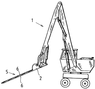
Fig. 1 represents a general view of the con-
nection of the land clearing device in accordance with
the invention to the head of a hydraulic boom assembly
construction 1 as connected to a working machine, and
its operation. Depending on the required working dis-
CA 02649588 2008-10-17
WO 2007/125158 PCT/F12007/000112
7
tance and the working machine used, the length of the
boom assembly and the number of joints may vary
freely. The substantial feature of the land clearing
device in accordance with the invention is that it
does not limit the selected working direction. The
land clearing device can be used freely in horizontal
direction, vertical direction and at different angles
at the required heights, within the rotation limits of
the joint construction of the boom assembly.
In the embodiment of Fig. 2, the land clear-
ing device comprises a body 2 from which it can be
connected to the boom assembly of the working machine.
Two straight, plate-like and elongated blade guides 6
(both shown in Fig. 1) are connected to the body 2.
Between the blade guides, two elongated blade panels 7
are placed such that their opposing surfaces rest
against each other and their outer surfaces rest
against the respective blade guides. Both blade panels
have, along their longer sides, blade rows 8, compris-
ing V-shaped blades 9. Both sides of the blades are
sharpened from the side of the blade guides such that
the sharp, cutting edges of the blades are flush with
each other and facing each other in the blade panels.
A rotating hydraulic motor 3 is supported on
the body 2, the connecting rods 11 connected to both
ends of the crank shaft 10 of said motor. In Fig. 2,
one of the connecting rods is connected to the lower
blade panel and the other is connected to the upper
blade panel. In this case, as the hydraulic motor 3
rotates, both blade panels 7 reciprocate between the
blade guides 6 at the same pace and always in opposite
directions, the sharp edges of the blades intersecting
each other and cutting the material caught between
them. For the cutting and operating characteristics of
the device, it is substantial that the blades which
cut in the same way are positioned on both sides of
the device, so that cutting is achieved every time the
CA 02649588 2008-10-17
WO 2007/125158 PCT/F12007/000112
8
device is moved. Similarly, it is substantial that
both blade panels move relative to the body of the de-
vice, so that any single blade cannot hit the object
intended for cutting and become stuck in it; instead
the objects intended for cutting always end up in the
spaces between the blades and therefore break with
certainty.
Fig. 3 represents a second embodiment of the
invention in which the blades of the cutting blade
panels differ from the embodiment of Fig. 1, and a hy-
draulic cylinder 4 is used as the power unit. The
blade construction is presented in detail in Fig. 5.
As to the hydraulic cylinder, it is a double hydraulic
cylinder in which the cylinder capacities are equal on
both sides of the piston. In this case, when the hy-
draulic cylinder is controlled by means of constant
oil flow, the motion of the piston and, therefore, of
the blade becomes uniform and equally fast in both di-
rections.
In this embodiment, the piston rod 14 of the
hydraulic cylinder is connected to only one of the
blade panels 7, and the blade panels are mechanically
interconnected by means of a lever mechanism 12. The
lever mechanism 12 comprises a rigid lever 15, pivo-
tally connected at the center to the blade guide 6,
one end of which lever being connected by means of a
joint 16 to the upper blade panel. The opposite end of
the lever 15 is connected to the lower blade panel by
means of a joint 17 through an elongated opening 18
provided in the topmost blade panel. Thus, as the hy-
draulic. cylinder reciprocates the topmost blade panel
between the blade guides 6, the lever 15 simultane-
ously moves the lower blade panel in opposite direc-
tions at the same speed. At the same time, the lever
15 limits the motion ranges of the blade panels 7 such
that they only move within the defined limits.
CA 02649588 2008-10-17
WO 2007/125158 PCT/F12007/000112
9
In Fig. 3, lubricating grooves 13 are also
schematically indicated in dashed line, which grooves
are preferably arranged on the blade guide and/or
blade panel surfaces which move against each other,
into which grooves lubricant is directed from the body
in a suitable manner, i.e. continuously or in cycles,
such that these four plate-like parts are able to move
easily relative to each other.
Fig. 4 represents a schematic view of a pre-
ferred embodiment of the invention which provides for
an extremely compact, powerful and reliable land
clearing device. It comprises, as in Figs. 2 and 3,
two blade panels 7, reciprocating between two blade
guides 6. In the figure, the hydraulic cylinder 19,
operating as the power unit, is connected to the lower
blade panel to move simultaneously with it. The con-
nection between the hydraulic cylinder 19 and the
lower blade panel is realized through an elongated
opening 22 provided in the upper blade panel. The up-
per blade panel, in turn, is connected to the piston
of the hydraulic cylinder, more particularly to the
piston rod 20, such that the piston and the upper
blade panel move together. The hydraulic cylinder is a
so called double hydraulic cylinder, in which the pis-
ton rod extends in both directions from the piston and
out of the cylinder as an evenly thick construction,
such that cylinder capacities on both sides of the
piston are equal. In this case, when the hydraulic
cylinder is controlled by means of constant oil flow,
the motion of the piston and, therefore, of the blade
becomes uniform and equally fast in both directions.
To prevent the blade panels 7 from moving
freely between the blade guides along their total
length, a rocker arm 21 is pivotally connected, sub-
stantially at its central point, to the body of the
device. One end of the rocker arm is pivotally con-
nected to the moving assembly formed by the hydraulic
CA 02649588 2008-10-17
WO 2007/125158 PCT/F12007/000112
cylinder 19 and the lower blade panel, and the other
end is pivotally connected to the moving assembly
formed by the piston rod 20 and the topmost blade
panel. The rocker arm construction therefore limits
5 the motion range of the blade panels between the blade
guides to a specific, reciprocating motion.
The land clearing device of Fig. 4 is compact
and light in all directions. It is also easily con-
trollable by means of, for example, electronically or
10 mechanically controlled hydraulic couplings (not shown
in the figure), wherein hydraulic pressure is alter-
nately directed to opposite sides of the piston of the
hydraulic cylinder.
The land clearing device in accordance with
the invention, and in particular the embodiment in ac-
cordance with Fig. 4, can also be easily built as a
very compact and light, manually operated hedge trim-
mer. In this case, the manually portable clearing de-
vice comprises a blade body, a blade, and a motor,
provided with suitable operating handles, the power
unit being connected to the hydraulic motor via hy-
draulic hoses of sufficient length. The oil pump and
the motor, either a combustion motor or an electric
motor, rotating the pump may, therefore, be positioned
farther from the object, within the limits defined by
the length of the hydraulic hoses. It is also possible
that the oil pump and the light combustion motor form
an assembly designed to be carried on one's back or
pulled along on wheels, so that the trimmer is easy to
use in all surroundings.
Fig. 5 represents a more detailed view of one
blade construction in accordance with the invention,
which can be used in all land clearing devices in ac-
cordance with the invention, a more general descrip-
tion of which has been given in the context of the em-
bodiment of Fig. 3. Both opposing blade rows comprise
a set of blades 23, the opposing surfaces 29 of which
CA 02649588 2008-10-17
WO 2007/125158 PCT/F12007/000112
11
being straight and flat. The blades have knife-like,
cutting sides 24, approaching each other toward the
point, and an efficient, wood-milling point construc-
tion 25.
The point construction 25 comprises a
straight and triangular point surface 26, which has a
base 30, parallel to the opposing surface of the oppo-
site blade, and milling edges 27, extending toward
each other from the base and slightly curving inwards.
Slanted guiding surfaces 28, curving at first toward
each other, depart from the milling edges 27 to curv-
edly meet the straight knife-like sides 24. Inward-
curving and cutting lower edges 31 of the guiding sur-
faces 28 form in the blades moving against each other
a powerful, cutting, round-shape mouth, which cuts
most of the material caught between the blades. The
rest of the material is cut between the knife-like,
long sides 24, as the blades move against each other,
the opposing surfaces 29 tightly engaged.
The invention is not limited merely to the
examples referred to above; instead many variations
are possible within the scope of the inventive idea
defined by the claims.