Note: Descriptions are shown in the official language in which they were submitted.
CA 02649657 2010-08-12
CWCAS-200 -
APPARATUS FOR CUTTING POTATOES OR SIMILAR VEGETABLES
BACKGROUND OF THE INVENTION
[0002] The present invention generally relates to cutting methods and
equipment. More particularly, this invention relates to an apparatus equipped
with an impeller assembly that positions and orients elongate food products
prior to encountering a cutting device that produces size-reduced products of
generally consistent thickness.
[0003] Various types of equipment are known for slicing, shredding and
granulating food products such as vegetables, fruits, and meat products. A
particular example is slicing equipment adapted for cutting root vegetables
such as potatoes into thin slices suitable for making potato chips (also known
as potato crisps). A widely used machine for this purpose is commercially
available from Urschel Laboratories, Inc., under the name Urschel Model
CC . The Model CC is a centrifugal-type slicer capable of producing
uniform slices, strip cuts, shreds and granulations of a wide variety of food
products at high production capacities. When used to produce potato slices
for potato chips, the Model CC can make use of substantially round potatoes
to produce the desired circular chip shape with a minimum amount of scrap.
Descriptions pertaining to the construction and operation of the Model CC ,
including improved embodiments thereof, are contained in U.S. Patent Nos.
5,694,824 and 6,968,765.
-1-
CA 02649657 2010-08-12
CWCAS-200
[0004] Figures 1 and 3 are perspective views of an impeller 10 and
cutting head 12, respectively, of types that can be used in the Model CC
machine. In operation, the impeller 10 is coaxially mounted within the cutting
head 12, which is generally annular-shaped with cutting knives 14 mounted on
its perimeter. The impeller 10 rotates within the cutting head 12, which
remains stationary. Each knife 14 projects radially inward toward the impeller
and in a direction generally opposite the direction of rotation of the
impeller
10, and defines a cutting edge at its radially innermost extremity. The
impeller
10 has generally radially-oriented paddles 16 with faces 34 that engage and
direct food products (e.g., potatoes) 36 radially outward against the knives
14
of the cutting head 12 as the impeller 10 rotates. The paddles 16 are shown
as oriented to have what is termed herein a negative pitch, which as viewed in
Figure 2 denotes that the face 34 of each paddle 16 has a radially innermost
extent angled away from the direction of rotation of the impeller 10 relative
to
a radial 38 of the impeller 10 terminating at the radially outermost extent of
the
face 34. Such an orientation has been found to be preferred with'the impeller
10 and cutting head 12 of Figures 1 through 3. The impeller 10 is typically
formed as a casting, such as from a manganese aluminum bronze (MAB)
alloy, and therefore has a unitary construction.
[0005] The cutting head 12 shown in Figure 3 comprises a lower
support ring 18, an upper mounting ring 20, and circumferentially-spaced
support segments 22. The knives 14 of the cutting head 12 are individually
secured with clamping assemblies 26 to the support segments 22, which are
pivotally attached to the support and mounting rings 18 and 20, such as with
one or more coaxial pins (not shown) that engage holes in the support and/or
mounting rings 18 and 20. By pivoting on the pins, the orientation of a
support
segment 22 can be adjusted to alter the radial location of the cutting edge
-2-
CA 02649657 2008-10-17
WO 2007/124039 PCT/US2007/009635
of its knife 14 with respect to the axis of the cutting head 12, thereby,
controlling the
thickness of the sliced food product. As an example, adjustment can be
achieved with
an adjusting screw and/or pin 24 located circumferentially behind the pivot
pins. Figure
3 further shows gate insert strips 23 mounted to each support segment 22
immediately
downstream of each knife 14. The gate insert strips 23 do not cover the entire
axial
extent of the cutting head 12, but instead define an opening 25 at each of
their lower
ends through which rocks and other debris that settle by gravity toward the
bottom of
the impeller 10 can feed through the cutting head 12 without damaging the
knives 14.
[0006] The knives 14 can be attached to their respective support segments with
bolts, clamping assemblies, etc. Figures 9 and 10 are cross-sectional views
through a
portion of the cutting head 12 looking toward the lower support ring 1.8.
Figure 9 shows
a knife 14 held in place with a clamping assembly 26 comprising inner and
outer
holders 27 and 28 secured with bolts 29 to a support segment 22, generally as
described in U.S. Patent No. 6,968,765 and particularly in reference to Figure
7 of this
prior patent. Figure 10 shows a knife 14 encased in a plastic cartridge 30,
which helps
to protect the knife 14 from damage by rocks and other debris that may be
embedded
in or otherwise present with the food products being fed through the impeller
10. The
knife 14 and its plastic cartridge 30 are held in place between a pair of
holders 27 and
28, with the radially outer holder 28 being forcibly held in place on the
support segment
22 with a damping rod 32. The clamping rod 32 is shown oriented perpendicular
to the
support and mounting rings 18 and 20, and secured to the radially inner holder
27 with
a fastener 31. Rotating a lever 33 creates a camming action that forces the
outer
holder 28 outward against the rod 32, and forcing the outer holder 2Q against
the knife
14. In each case, the knives 14 are disposable and must be replaced to
maintain the
cutting efficiency of the cutting head 12 and the quality of the sliced food
product. The
cutting edge 15 of each knife 14 is shown in Figures 9 and 10 as being formed
to have
a double bevel. As evident from Figure 9, the trajectory 35 of slices produced
at the
-3-
CA 02649657 2008-10-17
WO 2007/124039 PCT/US2007/009635
knife edge 15 is free of any obstacles downstream and radially outward from a
plane
defined by the outer surface of the outer holder 28. In Figure 10, the plastic
cartridge
30 deflects slices away from the clamping rod 32.
[0007] While the Model CC has performed extremely well for its intended
purpose, further improvements are continuously desired and sought for slicing
machines of the type represented by the Model CC . For example, knives with
double
bevels as shown in Figures 9 and 10 tend to compress food product during
slicing. In
the case of slices cut from potatoes and cooked in oil to produce potato
chips,
compression during slicing can be sufficient to cause starch loss, which
undesirably
promotes oil absorption during cooking. While single-bevel knives reduce
compression,
they reduce the trajectory angle to the extent that the slices tend to impact
the clamping
rod 32 downstream. Though the plastic cartridge 30 avoids this by deflecting
slices
away from the clamping rod 32, the compressibility of the plastic material
reduces the
precision with which the cutting edges 15 of the knives 14 can be located,
making
production of slices with consistent thicknesses difficult. Other variab i les
that can affect
the operation of the Model CC slicing machine and/or reduce the consistency
of slices
include the presence of contaminants such as stones embedded or mixed in with
the
products, which can damage the cutting edges of the knives, and the use of
small
products that tend to roll within the impeller 10.
BRIEF SUMMARY OF THE INVENTION
[0008] The present invention provides a cutting apparatus having an annular-
shaped cutting head and an impeller assembly coaxially mounted for rotation
within the
cutting head. The impeller assembly rotates about an axis of the cutting head
in a
rotational direction relative to the cutting head to deliver round food
products radially
outward toward the cutting head. The cutting head has at least one knife
extending
-4-
CA 02649657 2008-10-17
WO 2007/124039 PCT/US2007/009635
radially inward toward the impeller assembly in a direction opposite the
rotational
direction of the impeller assembly. The knife has a cutting edge at a radially
innermost
extremity thereof and a radially outer face that defines a trajectory plane
for slices
removed from the food products by the cutting edge.
[0009] According to one aspect of the invention, the knife is clamped to the
cutting head with a clamping feature that includes a clamping bar with which
the
clamping feature generates a clamping force to secures the knife to the
cutting head.
The clamping bar is located adjacent a radially outermost extremity of the
knife,
oriented substantially parallel to the knife, and has a thickness in a radial
direction of
the cutting head that decreases in a direction toward the knife to provide
clearance for
the slices when traveling the trajectory plane of the knife. A significant
advantage of
this aspect of the invention is that slices of food product can be ejected
from the cutting
head without striking any structure downstream, and without resorting to the
use of a
double-beveled knife or sheathing the knife in a plastic cartridge. As such,
the knife
can have a single-bevel cutting edge to minimize compression of the product,
and the
cutting edge of the knife can be located with greater precision to produce
slices with
more consistent thicknesses.
[0010] The impeller assembly is preferably equipped with paddles to deliver
the
food products radially outward toward the cutting head. According to another
aspect of
the invention, each paddle has a radially outer extremity adjacent a periphery
of the
impeller assembly, an oppositely-disposed radially inner extremity, and a face
between
the radially inner and outer extremities and facing the rotational direction
of the impeller
assembly. Each paddle has grooves parallel to the radially outer extremity
thereof.
According to yet another aspect of the invention, each paddle has a plurality
of
removable posts mounted to its radially outer extremity and extending in a
radially
i
outward direction of the impeller assembly. A significant advantage achieved
with the
-5-
CA 02649657 2008-10-17
WO 2007/124039 PCT/US2007/009635
grooved paddles is to discourage smaller food products from rolling within the
impeller.
A significant advantage achieved with the removable posts is to avoid stones
and other
contaminants mixed with the product from being forced into and damaging the
knife
cutting edge.
[0011] Other objects and advantages of this invention will be better
appreciated
from the following detailed description.
BRIEF DESCRIPTION OF THE DRAWINGS
[0012] Figures 1 and 2 are perspective and cross-sectional views,
respectively,
of an existing impeller for the Model CC slicer.
[0013] Figure 3 is a perspective view of an existing cutting head for the
Model
CC slicer.
[0014] Figures 4A, 4B, and 4C are perspective, side, and cross; sectional
views,
respectively, of an impeller assembly suitable for use with the Model CC
slicer in
accordance with a preferred embodiment of the invention.
[0015] Figure 4D shows plan, perspective, and cross-sectional views of a
deflector for use with the impeller assembly of Figures 4A and 4B in
accordance with an
optional aspect of the invention.
[0016] Figures 4E, 4F, and 4G are perspective, side, and cross-sectional
views,
respectively, of an impeller assembly suitable for use with the Model CC
slicer in
accordance with an alternative embodiment of the invention.
-6-
CA 02649657 2008-10-17
WO 2007/124039 PCT/US2007/009635
[0017] Figure 5 is a cross-sectional view of the impeller assembly of Figures
4A,
4B, and 4C assembled with the deflector of Figure 4D and mounted :within the
cutting
head of Figure 3.
[0018] Figures 6A and 6B are isolated top and side views, respectively, of an
impeller paddle of the impeller assembly of Figures 4A, 4B, and 4C.
[0019] Figure 7 is an isolated side view of an impeller paddle of the impeller
assembly of Figures 4E, 4F, and 4G.
[0020] Figure 8 is a cross-sectional view of an edge portion of the impeller
assembly of Figures 4A, 4B, and 4C, schematically showing a single impeller
paddle
engaged with food products of. various sizes.
[0021] Figures 9 and 10 are cross-sectional views showing portions of existing
cutting heads used with the Model CC slicer.
[0022] Figures 11, 12, and 13 are cross-sectional views showing portions of
modified cutting heads suitable for use with the Model CC slicer, and
particularly the
impeller assembly of Figures 4A, 4B, and 4C, in accordance with different
embodiments
of the invention.
[0023] Figures 14 and 15 are side and cross-sectional views, respectively, of
a
clamping assembly shown in Figure 13.
DETAILED DESCRIPTION OF THE INVENTION
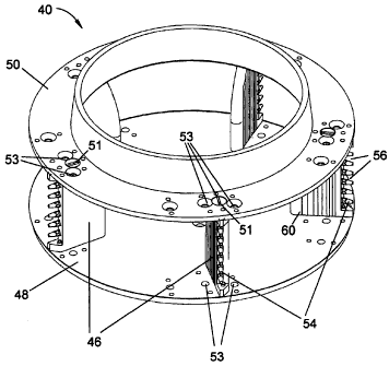
[0024] Figures 4A, 4B, and 4C show a modified impeller assembly 40 in
-7-
CA 02649657 2008-10-17
WO 2007/124039 PCT/US2007/009635
accordance with the present invention. As depicted in Figure 5, the impeller
assembly
40 is configured for rotation within cutting heads similar to the cutting head
12 of Figure
3, as well as cutting heads 42 configured in accordance with Figures 11
through 13.
[0025] Similar to the impeller 10 of Figures 1 and 2, the impeller assembly 40
has
generally radially-oriented paddles 46 with faces 60 that engage and, direct
food
products (e.g., potatoes) radially outward against knives of the cutting head
as the
impeller assembly 40 rotates. However, as evident from Figures 4A,1 4B, and
4C, the
paddles 46 are significantly different in construction and configuration from
the prior art
paddles 16 of Figures 1 and 2. Because of the configuration of the paddles 46,
the
impeller assembly 40 is preferably constructed of individually formed. paddles
46
mounted and secured between a pair of annular-shaped plates 48 and 50. As a
result
of its modular construction, the impeller 40 and its components can be formed
by
processes other than casting, and formed of various materials in addition to
commonly-
used MAB alloys.
[0026] Each of the paddles 46 is shown in Figure 4A as being ;individually
mounted with bolts 51 and pins 52 to a corresponding set of mounting holes 53
machined in the plates 48 and 50. The placement of the mounting holes 53
determines
the orientation or pitch of each paddle face 60 relative to a radial 64 of the
impeller
assembly 40 terminating at the radially outermost extent of the paddle face
60. The
pitch of the paddle faces 60 can be negative (such as the orientation !seen in
Figure 2),
neutral (meaning that the face 60 of each paddle 46 lies in the radial.64 of
the impeller
assembly 40), or positive (such as the orientation seen in Figures 4C, in
which the
radially innermost extent 66 of each paddle face 60 is angled toward,the
direction of
rotation of the impeller assembly 40 relative to the radial 64). A single set
of holes 53 is
provided for each paddle 46 so that the paddles 46 for a given impeller
assembly 40
are limited to having a negative, neutral, or positive pitch, as may be
desired. In an
-8-
CA 02649657 2008-10-17
WO 2007/124039 PCT/US2007/009635
alternative embodiment shown in Figures 4E, 4F, and 4G, multiple sets of
mounting
holes 53 are provided in the plates 48 and 50 to enable reorientation of the
pitch of
each paddle 46 on the impeller assembly 40.
[0027] Figures 6A and 6B show an individual paddle 46, which can be seen as
symmetric in the axial direction of the impeller assembly 40 (from top to
bottom in
Figure 4A and 4B). The radially innermost extent 66 of each paddle 46 is
generally
straight and axially-oriented. Suitable dimensions for the paddle 46 will
depend in part
on the size of the food products being processed, and therefore can vary
considerably.
For accommodating food products with diameters up to about four inches (about
ten
centimeters), a suitable radial width for each paddle 46 is up to about two
inches, as
measured from the radially outermost extent of the paddle face 60 to a line at
the
intersection of the paddle face 60 and a radius defining the radially
innermost extent 66
of the paddle 46. Figure 7 shows an individual paddle 46 of the alternative
embodiment
of Figures 4E, 4F, and 4G. The alternative paddle 46 of Figure 7 is asymmetric
in the
axial direction of the impeller assembly 40 (from top to bottom in Figure 4E
and 4F), in
contrast to the paddles 16 of Figures 4A through 4C, 6A, and 6B. The radially
innermost extent 66 of each alternative paddle 46 is generally straight and
axially-
oriented adjacent the lower plate 48, but with a boundary 68 adjacent the
upper plate
50 that curves radially outward as it approaches the upper plate 50. Though
not
required, this shape and contour for the innermost extent of each paddle 46
has the
desirable effect of reducing damage to food products being processed.
[0028] The Figures depict the paddles 46 as being equipped with multiple posts
54 located and spaced along their radially outermost extent, forming multiple
gaps 56
through which rocks and other debris can pass and exit the impeller assembly
40 and
subsequently the cutting head without damaging the paddles 46 of the impeller
assembly 40 or the knives of the cutting head. The posts 54 are preferably
-9-
CA 02649657 2008-10-17
WO 2007/124039 PCT/US2007/009635
replaceable, such as by threading into a face 58 machined into the radially
outermost
extent of each paddle 46. The posts 54 have generally conical shapes, and are
preferably angled so that a profile of its conical shape is coplanar with the
face 60 of its
paddle 46, as seen in Figure 6. As most readily evident from Figures 4, 5, and
7, the
face 60 of each paddle 46 has axially-oriented grooves 62 to inhibit food
product from
rotating while engaged by the paddle 46. The distances between adjacent
grooves 62
is shown as decreasing in the direction toward the outside diameter of the
impeller
assembly 40, since smaller food products (such as potatoes two inches (about
five
centimeters) and smaller) are usually rounder in shape and have less mass, and
are
therefore more likely to roll while they are engaged by a paddle 46. It is
believed that,
in combination, the grooves 62 on impeller paddles 46 having a positive pitch
provide
an optimal anti-rolling effect when small potatoes are being fed through the
impeller
assembly 40.
[0029] Figure 4D represents a deflector 90 for use with either of the impeller
assemblies 40 of this invention. The deflector 90 is tapered to generally have
an
inverted cone-shape to direct food products radially outward toward the
impeller
paddles 46. The deflector 90 is further formed to have a central semispherical
depression or recess 92. The function of the recess 92 is to cause water (or
another
lubricating fluid commonly used in food processing) originally directed
downward toward
the recess 92 to be redirected radially outward toward the upper ends of the
paddles
46, and thereafter cascade down the vertical surfaces of the paddles 46 to
provide a
lubricating and cleaning effect. The deflector 90 has a central bore 94 for
centrally
locating the deflector 90 on the lower plate 48 of the impeller assembly 40 as
shown in
Figure 5, and a countersunk bore 96 for receiving a bolt (not shown) to secure
the
deflector 90 to the lower plate 48.
[0030] Figure 5 schematically represents the impeller assembly 40 of Figures
4A
-10-
CA 02649657 2008-10-17
WO 2007/124039 PCT/US2007/009635
through 4C equipped with the deflector 90 of Figure 4D and coaxially and
concentrically
mounted for rotation within the cutting head 12 of Figure 3. The cutting head
12 is
supported on a stationary frame 13, while the impeller assembly 40 is coupled
to a drive
shaft 41. The righthand side of Figure 5 is a cross-section of gate insert
strip 23
mounted to a support segment 22 immediately adjacent a knife (not shown), and
shows
the gate insert strip 23 as not covering the entire axial extent of the
paddles 46.
Instead, the gate insert strip 23 -defines an opening 25 at its lower en a
through which
rocks and other debris that settle by gravity toward the bottom of the
impeller assembly
40 can feed through the cutting head 12 without damaging the knife. ;
[0031] Figure 8 schematically represents a plan view of the impeller assembly
40
of Figures 4E through 4G, with the upper plate 50 removed and round potatoes
72 of
different diameters engaged with one of its paddles 46. From Figure-8, it can
be seen
that a four-inch diameter potato is tangent to the face 60 of the paddle 46 at
a point on
the intersection of the face 60 with a radius of the straight inner boundary
66 of the
paddle 46, evidencing that the paddle 46 is sized to accommodate food products
with
diameters up to four inches (about 10 cm). The paddle 46 is shown in Figure 8
as
having a positive pitch of about five degrees. If the paddle 46 were mounted
to the next
set of mounting holes 53 above the paddle 46 (as viewed in Figure 8), the
paddle 46
would be angled an additional five degrees, providing a positive ten-degree
pitch. If the
paddle 46 were mounted to the next set of mounting holes 53 below the paddle
46 (as
viewed in Figure 8), the paddle 46 would have a neutral pitch.
[0032] Figures 11, 12, and 13 are cross-sectional views showing portions of
cutting heads 42 configured with different knife clamping hardware according
to various
embodiments of the invention. In each case, knives 44 are secured with a pair
of
holders 74 and 76, with the radially outer holder 76 being forcibly held in
place on its
support segment 70 with a clamping rod 78, essentially as described for Figure
10.
-11-
CA 02649657 2008-10-17
WO 2007/124039 PCT/US2007/009635
However, none of the knives 44 represented in Figures 11 through 13 are
sheathed in a
plastic cartridge as done in Figure 10. The intent of omitting the plastic
cartridge 30 of
Figure 10 is to more accurately locate the cutting edge 45 of each knife 44
relative to
the axis of the cutting head 42 to achieve improved slice thickness accuracy
and
consistency. Specifically, the pliability of plastic materials renders the
plastic cartridge
30 compressible, which reduces to some extent that accuracy with which the
knife
cutting edges 45 can be radially located with respect to the axis of the
cutting head 42.
Therefore, eliminating the cartridge 30 and forming the knife 44 and its
holders 74 and
76 of substantially incompressible materials, such as metal, eliminates the
dimensional
changes that occur from compression under the clamping load of the rod 78, and
ensures more accurate positioning of the knife cutting edges 45.
[0033] In Figure 11, a conventional double-beveled knife 44 is'shown
essentially
similar to the knife 14 of Figure 9. In practice, the trajectories 35 of
slices traveling
downstream from the knife 44 (as,determined by the radially outer face 82 of
the knife
44 and the radially outer holder 76) is such that slices are likely to hit the
clamping rod
78. As a first solution, Figure 12 shows the clamping rod 78 as having a half-
round
cross-section, which allows the clamping rod 78 to have a sufficiently; lower
profile that
is radially inward from the trajectories 35 of slices exiting the knife 441
The knife 44 of
Figure 12 is also supported by an insert 80, such that the knife 44 is between
the insert
80 and the inner holder 74. The insert 80 serves to protect the edge of the
inner holder
74 from stones or other debris that are often unintentionally fed through the
impeller
assembly 40 along with food products.
[0034] In contrast to the knives 44 described thus far, the knife 44 shown in
Figure 13 is beveled only on its radially outer surface 82. According to the
present
invention, a single-beveled knife edge 45 is believed to produce a cleaner
slice and
reduce the compression of food products during the slicing operation observed
with the
-12-
CA 02649657 2008-10-17
WO 2007/124039 PCT/US2007/009635
double-beveled knives 14 and 44 of Figures 9 through 12. However; as a result
of
lacking a bevel on its outer surface 82, the single-beveled knife 44 of Figure
13 does
not deflect slices to the extent that the double-beveled knives 14 and 44 of
Figures 9
through 12 are capable. To avoid slices impacting the clamping rod !78, Figure
13
shows the clamping rod 78 as generally having the form of a rectilinear bar
with a
tapered leading edge 84, resulting in the rod 78 having a sufficientlylower
profile
proximate to the knife 44 that is radially inward from the trajectories 35 of
slices exiting
the knife 44.
[0035] Figures 14 and 15 illustrate the clamping action performed by the
clamping rod 78 in more detail. The embodiment shown in Figures 114 and 15
combine
the insert 80 of Figure 12 with the tapered damping rod 78 of Figure! 13. As
evident
from Figures 14 and 15, the lever 77 has forced one end of the outer holder 76
against
the clamping rod 78, which in turn forces the opposite end of the outer holder
76 into
engagement with the knife 44, forcing the knife 44 against the inner holder
74. The
knife 44 can be release by rotating the lever 77 clockwise (as viewed in
Figure 15),
such that a flat 86 on the lever 77 faces the outer holder 76, releasing the
outer holder
76 from its engagement with the clamping rod 78.
[0036] While the invention has been described in terms of specific
embodiments,
it is apparent that other forms could be adopted by one skilled in the art.
For example,
the physical configurations of the impeller assembly 40, cutting head !42, and
their
components could differ from that shown, and materials and processes other
than
those noted.could be use. Therefore, the scope of the invention is to be
limited only by
the following claims.
-13-