Note: Descriptions are shown in the official language in which they were submitted.
CA 02649801 2008-12-15
WO 2007/143773
PCT/AU2006/001122
MICROTUNNELLING SYSTEM AND APPARATUS
Field of the Invention
This invention relates to underground boring and more particularly to an
improved
microttmnelling system and apparatus.
In this document "microtunnelling" is considered to comprise trenchless
horizontal
boring of a bore of the order of 600 millimetres and less.
Background of the Invention
Modern installation techniques provide for underground installation of
services
required for community infrastructure. Sewage, water, electricity, gas and
telecommunication services are increasingly being placed underground for
improved
safety and to create more visually pleasing surroundings that are not
cluttered with
open services.
Currently, the most utilised method for underground works is to excavate an
open cut
trench. This is where a trench is cut from the top surface and after insertion
of piping
or optical cable is then back-filled. This method is reasonably practical in
areas of new
construction where the lack of buildings, roads and infrastructure does not
provide an
obstacle to this method. However, in areas supporting existing construction,
an open
cut trench provides obvious disadvantages, major disruptions to roadways and
high
possibility of destruction of existing infrastructure (i.e. previously buried
utilities).
Also, when an open cut trench is completed and backfilled the resultant shift
in the
ground structure rarely results in a satisfactory end result as the trench
site often sinks.
Open trenches are also unsafe to pedestrians and workers.
Another concept employed for underground works is that of boring a horizontal
underground hole. Several methods employ this philosophy as it generally
overcomes
the issues of disruption to roads and infrastructure as described for open cut
trenches
however even these methods have their inherent problems.
1
CA 02649801 2008-12-15
WO 2007/143773
PCT/AU2006/001122
One method is horizontal directional drilling (HDD). In this method a boring
device is
situated on the ground surface and drills a hole into the ground at an oblique
angle
with respect to the ground surface. A drilling fluid is typically flowed
through the drill
string, over the boring tool, and back up the borehole in order to remove
cuttings and
dirt. After the boring tool reaches a desired depth, the tool is then directed
along a
substantially horizontal path to create a horizontal borehole. After the
desired length
of borehole has been obtained, the tool is then directed upwards to break
through to
the surface. A reamer is then attached to the drill string, which is pulled
back through
the borehole, thus reaming out the borehole to a larger diameter. It is common
to
attach a utility line or other conduit to the reaming tool so that it is
dragged through
the borehole along with the reamer. A major problem with this method is that
the
steering mechanism is extremely inaccurate and unsuitable for applications on
grade.
The stop and start action utilised by the operator results in a bore that is
not
completely straight. The operator has no way of knowing exactly where the hole
goes
which can result in damage to existing utilities. This. could pose a safety
threat
particularly if the services in the area are of a volatile nature.
Another method is the pilot displacement method. This method uses a drill
string
pushed into the ground and rotated by a jacking frame. A theodolite is focused
along
the drill string as a point of reference to keep the line on grade. This
system is not
accurately steered. The slant on the nose is pointed in the direction of
intended
steering. The position of the head is monitored through a total station with a
grade and
line set and measuring this point against a target mounted in the head of the
pilot
string. If the ground conditions are homogenous and the conditions absolutely
perfect,
it will produce a satisfactory bore. Unfortunately this is rarely the case.
Ground
conditions are generally variable the pilot tube will tend to steer towards
whichever
ground offers the least resistance irrespective of the direction in which you
are the
steering. As the drill strings are generally short, the time to drill is often
slow with
repeated connections making the process tedious. Once the bore reaches the
reception
shaft augers are attached and pulled back along the bore to displace the spoil
into the
reception shaft. This then has to be manually removed which is time consuming.
2
CA 02649801 2008-12-15
WO 2007/143773
PCT/AU2006/001122
Slurry style microtunnelling utilises slurry reticulation to transport spoil
removal
throughout the installation process. Two lines are fed via a starting shaft
along the
bore. The pipes are jacked via a hydraulic jacking frame into the hole. Water
is forced
along the feed pipe to the cutting face where the spoil slurry of rock and mud
is forced
back along the return pipe. Whilst enjoying a good degree of accuracy, this
system
requires a structural shaft that needs a massive amount of force to push the
pipes. This
results in a large, expensive jacking shaft pit that is time consuming to
build. The
sheer weight and size of the components make them slow to connect and
cumbersome
to use. If the unit becomes damaged or stuck in the bore, the only method
available to
retrieve the unit would be to dig down onto the drill head location.
In one form of boring machine shown by US Patent Application No.US2004/0108139
to Davies and corresponding to Australian Patent 2003262292 there is disclosed
a
micro tunnelling machine having a tunnelling head with a boring bit which is
forced
in a horizontal direction by an hydraulic thruster. The direction of the head
is laser
guided. The beam strikes a target in the head and a camera relays an image of
the
target to an operator located at the tunnel entrance. The operator adjusts the
direction
by admitting water and draining water from a pair of rams inside the head,
which
move the boring bit up and down or left and right. A semi automatic version is
disclosed in which a microprocessor adjusts the direction until the operator
assumes
control. In particular the invention is claimed to be a guidance system for
the boring
head of a micro-tunnelling machine of the type which bores in a selected
direction and
inclination using laser beam guidance having the endmost part of the drive to
the
boring bit adjustable in two directions at 90 , wherein, the endmost part of
the drive
has a target for the laser beam, means to convey an image of the target and
the laser
strike position thereon to an operator situated remotely from the boring head
and input
means for the operator to adjust the direction of the endmost part of the
drive.
The major approach of the directional control of the disclosed apparatus of US
Patent
Application No.US2004/0108139 to Davies is to have the drive shaft connected
at its
end distal to the cutting edge in a manner that allows the drive shaft to move
as
required and to allow the cutting element to be redirected to correct position
as
3
CA 02649801 2008-12-15
WO 2007/143773
PCT/AU2006/001122
determined by the laser controlled directional system. However this form of
apparatus
places all the strain on an elongated movable drive shaft retained by
cylinders and
therefore readily increases the risk of breakage. There is clearly a need to
provide an
improved system to decrease chance of breakage of the drill head components.
It can be appreciated that present methods of underground tunnelling are
cumbersome,
inaccurate; and require repeated halting of boring operations due to waste
removal and
heating effects. Moreover, there is an inherent delay resulting from
replacement of
parts of conventional boring systems since it usually requires the boring tool
to be
recovered from the site and returned to the assembly factory. Recovery in
itself can be
cumbersome and expensive particularly if a new vertical access hole is
required to
recover the tool. This could damage the road or services under which the bored
tunnel
is extending. Further present systems are4mable to accurately remain on fixed
boring
direction, which are often needed when a buried obstruction is detected or
changing
soil conditions are encountered.
Summary of the Invention
In accordance with the invention there is provided an apparatus and method for
underground boring on grade more particularly to an improved microtunnelling
system and apparatus.
In this document "microtunnelling" is considered to comprise trenchless
horizontal
boring of a bore of the order of 600 millimetres and less. This is
particularly relevant
to the insurgenceof pipes of the order of around 300 millimetres.
The drawbacks of current microtunnelling technology are significant and have
been
overcome or are at least ameliorated by the current invention including one or
more of
the following improvements and other improvements as will be understood from
the
description.
A first fundamental improvement is the use of an external casing with flow
channels
therein and the drive rod mounted therein and allows for all cabling and
hosing to be
4
CA 02649801 2014-07-22
mounted in an external cavity, which thereby allows for continuous cabling
over a plurality of
encased intermediate drill rods.
A second fundamental improvement is the incorporation of the driveline within
the vacuum
chamber. Incorporating the rotation within the vacuum achieves multiple goals.
Firstly, the
vacuum area can be dramatically increased and so maximize the machines ability
to remove
spoil and in such increased productivity. Secondly, the rotation component of
the drill rod
generates heat. The removal of this heat from the laser area is critical to
laser accuracy. By
combining the rotation into the vacuum area, any heat generated is immediately
removed
and the laser therefore is unaffected.
A third fundamental improvement is the steering mechanism of the encased drill
rod using
radially protrusions engaging steering shell to direct the drill head and
prevent any undue
force on the drill head centrally mounted within the casing.
A fourth fundamental improvement is the modular structure of the drill head by
a plurality of
disc like modules that can be created by direct external etching, drilling or
casting or the like
and be combined in cylindrical shells to form a readily assembled drill head.
A fifth fundamental improvement is the modular components of the drive means
that allows
for differing rotational units to be used with a thrust unit that provides
linear pull as well as
push capabilities. This allows matching of rotational units to material being
bored and size of
pipe being inserted and further allows for reverse reaming to a larger
diameter after initial
bore has been accurately drilled.
According to the present invention, there is provided a microtunnelling
apparatus including a
drill head section connected to a distal end of one or more intermediate drill
rods, which can
be driven by an external drive means, and wherein addition of further
intermediate drill rods
forms a string of intermediate drill rods that allows extension of the boring
hole created by
the drill head section, wherein each of the intermediate drill rods includes a
drive shaft
5
CA 02649801 2014-07-22
mounted within a casing, wherein each of the intermediate drill rods includes
a front end and
a rear end, wherein each front end and rear end includes a bearing, wherein
each bearing
provides rotational mounting of each of the drive shafts within each of the
casings, and
wherein the bearings hold each drive shaft within each intermediate drill rod,
wherein each
of the casings defines a plurality of axially extending cavities, and wherein
the cavities of the
casings of the intermediate drill rods in the string of intermediate drill
rods align to form a
plurality of separate continuous channels that extend along the length of the
string of
intermediate drill rods.
Brief Description of the Drawings
In order that the invention is more readily understood an embodiment will be
described by
way of illustration only with reference to the drawings wherein:
Figure 1 is a perspective view of a drive means of a microtunnelling system
and
apparatus in accordance with the invention including a thrust module and
rotation
module mounted on a rack system and further including a vacuum for assisting
return
5a
CA 02649801 2008-12-15
WO 2007/143773
PCT/AU2006/001122
slurry;
Figure 2 is a perspective exploded view of a drill head able to be driven by
the
drive means of Figure 1 for use in the microtunnelling system and apparatus in
accordance with the invention;
Figure 3 is a front view of an enclosed drill head with front cutting means
able
to be driven by the drive means of Figure 1 for use in the microtunnelling
system and
apparatus in accordance with the invention;
Figure 4 is a cross sectional view of the enclosed drill head with front
cutting
means of Figure 3 through section A-A;
Figure 5 is a cross sectional view of the enclosed drill head with front
cutting
means of Figure 3 through section B-B;
Figure 6 is a cross sectional view of the enclosed drill head with front
cutting
means of Figure 3 through section C-C;
Figure 7 show front and rear perspective views of the steering module of the
drill head of Figure 2;
Figure 8 is a side view of the of the steering module of Figure 7 and a cross
sectional view through section B-B;
Figure 9 show front and rear perspective views of the bearing module of the
drill head of Figure 2;
Figure 10 is a side view and a cross sectional view of a drill shaft;
Figure 11 show front and rear perspective views of the front bearing bush of
the drill head of Figure 2;
Figure 12 is a side view of the of the front bearing bush of Figure 11 and a
cross sectional view through section A-A;
Figure 13 is .a cross sectional view of the enclosed drill head showing the
pressure fluid path through the modules to the bearing module and the front
bearing
bush supporting the front cutting arm;
Figure 14 is a perspective view of a drive rod for extending between the drive
means of Figure 1 and the drill head of Figure 2
Figure 15 is a perspective reverse view of the drive rod of Figure 6;
Figure 16 is are end views of the drive rod of Figures 14 and 15 showing
mating male and female ends; and
6
CA 02649801 2008-12-15
WO 2007/143773
PCT/AU2006/001122
Figure 17 is a perspective detailed view of the drill rod of Figures 14 and 15
showing the toggle locking mechanism.
Figure 18 is a rear perspective view of a vacuum assisted precision reamer
showing the connection means to the drill rod and rearward facing cutting
face.
Figure 19 is a front perspective view of a vacuum assisted precision reamer of
Figure 18 showing the connection means to the product pipe to be installed.
Figure 20 is a rear perspective view of a vacuum assisted precision reamer of
Figure 18.
Figure 21 is a cross-sectional view through section A-A of Figure 20 of a
vacuum assisted precision reamer of Figure 18 showing the internal pressure
fluid
passages, vacuum cavity, air channel, input drive shaft, planetary gear set,
cutter hub
and bearing.
Detailed Description of the Invention
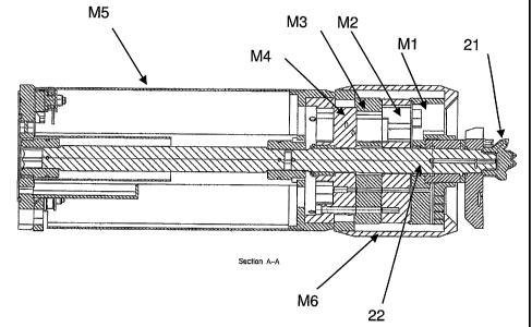
Referring to the drawings there is shown a microtunnelling apparatus and
system that
comprises a drive system (11), a drill head section (20) and intermediate
drill rods
(41) allowing extension of the boring hole created by the drill head section
driven by
the drive system.
The drive system (11) as shown in Figure 1 includes a power source and a track
system for allowing limited linear drive of the power source. The track system
includes a rack and pinion gearing system (12) to allow maintained linear
thrust
pressure along the length of the track. The power source includes a hydraulic
thrust
module (13), which reciprocates a rotation module (14) housed in the thrust
box in the
launch shaft. The product pipe can be either pushed or pulled into place for
pipeline
completion.
To the front of the rotation module (14) is attached encased intermediate
drill rods
(41) such as shown in Figures 14 and 15.
Attached to the distal end of the last intermediate drill rod (41) is attached
a drill head
(20) shown in exploded view in Figure 2 and in cross sectional views in
Figures 4, 5,
7
CA 02649801 2008-12-15
WO 2007/143773
PCT/AU2006/001122
and 6. As such a drill rotor assembly (21) connected to the end of the drill
shaft or
drill rod (22) and connecting to intermediate drill rods (23) form a
continuous drill
string that is driven by the external drive means (11) comprising the
hydraulic thrust
module (13), reciprocating a rotation module (14) and linearly movable on the
rack
and pinion gearing system (12).
The casing (42) of the intermediate drill rods (41) and the casing of the
drill head (20)
formed by the steering shell (M6) and the rear shell (M5) form a continuous
covering
of the continuous drill string with internal defined continuous bores or
channels. In
particular a vacuum channel (51), as shown particularly in Figure 16, can be
formed
by a number of continuous cavities extending along the length of the
intermediate drill
rods (41) to the drill head (20). This vacuum channel (51) has vacuum seals at
connecting female end (46) to maintain vacuum between longitudinally engaged
and
aligned intermediate drill rods. Within this vacuum channel 51 is located the
connecting intermediate drill rods (41). A separate air channel (52) is formed
by a
separate number of continuous cavities extending along the length of the
intermediate
drill rods (41) to the drill head (20). This forms a linear channel within
which the
controlling laser can penetrate to the drill head (20). By the separation of
the heat
generating drill rod (22) to the linear laser channel and the cooling effect
of the return
slurry along the vacuum channel (51) creates a highly effective and accurate
steering
mechanism.
The microtunnelling system and apparatus further includes:
a) drill head with fluid bearing bush and modular construction
b) enclosed drill rods with internal cooling system
c) pullback extraction reamer
d) rack and pinion thrust module with rotation unit
e) rod loading system
microprocessor control system.
In use upon excavation of a launching shaft, the base of the shaft would be
prepared
for the installation of the drilling machine. The shaft would typically have a
pipe
invert start point already marked and a line surveyed. A laser would be set up
in the
8
CA 02649801 2008-12-15
WO 2007/143773
PCT/AU2006/001122
shaft at the extreme rear on line and grade. Thick boards are typically placed
along the
base of the shaft horizontally on grade. The microtunnelling drive means (11)
including thrust module (13) and rotation unit (14) is lowered into the shaft
and set up
on line and grade.
The drill head (20) is lowered into the shaft and data, hydraulic and pressure
fluid
lines (44) are attached to the drill head (20). The drill head size and ground
conditions
are entered into the control panel which selects appropriate parameters for
drill thrust
speed and force, drill rotation speed and torque, vacuum flow and pressure,
and
pressure fluid flow. The drill head is attached to the vacuum thrust adaptor
mounted
on the rotation unit. Once set in launch mode, the vacuum unit is started and
the
pressurised drill fluid is actuated to eject at the drill face. The drill head
is launched
into the earth face.
The hole is cut via a combination of rotating cutting tooling and assisted by
ejecting
pressurised fluid. This pressurised fluid flow, which also acts as a fluid
bearing, is
shown in bold in Figure 13. Whilst drilling, the drill head (20) is thrust
into the
ground with the slurry/spoil being vacuumed up back into vacuum pipe (15) into
a
waste tank for removal. Once the drill head is completely in the ground the
thrust,
rotation, vacuum and pressure fluid is stopped. The drill head is detached
from the
vacuum thrust adaptor, and the thrust trolley with rotation unit return to the
starting
position.
Once in the start position an intermediate drill rod (41) is loaded either
manually with
a crane or via the use of the automated rod loader. Once the drill rod is
sitting in the
bed of the thrust module the thrust trolley and rotation unit are staited at
low speed,
low thrust and low torque respectively to engage the drill rod. The rod
engagement is
automatic in that the drill rod has self-aligning pins (48) that accurately
aligns the rod
to both the drill head and the drill machine. Upon full alignment and further
forward
,30 travel, the self-locking toggles (shown in detail in Figure 17) engage
behind the
locking pins to affect a solid connection. Control hoses and cables (44) are
inserted
into the concave cavity (43) of the outer cover or casing (42) encasing the
drill rod
9
CA 02649801 2008-12-15
WO 2007/143773
PCT/AU2006/001122
(23). Vacuum and pressure fluid resume with the drilling process reverting to
preset
drilling speed, thrust and torque. This process is continued until the final
bore end
point is reached.
Operation of the microtunnelling machine is performed remotely via a control
box,
which displays all the current pressure and speed settings. The control box is
computerised and integrates the control of the steering, thrust module,
rotation unit,
vacuum unit and the pressure fluid. The operator can adjust any of the
parametric
settings to perfectly suit the current ground conditions. Both the drilling
process and
the steering process can be automated via the use of integrated computer
software and
can also be manually controlled. Throughout the drilling process the drill
position is
monitored via the laser hitting a target positioned in the drill head (20) and
viewed
through the use of closed circuit television (CCTV) so that the operator or
software
package constantly steers the drill head to keep the laser in the centre of
the target.
Once the bore is complete there are three options; progress the drill rods
into the
reception shaft whilst inserting jacking pipes, pull back to the launching
shaft whilst
trailing a pipe directly behind it, or remove the drill rods prior to pipe
insertion.
Currently, the microtunnelling industry only allows for forward excavation.
The
current invention is the only system of microtunnelling that incorporates
precision
back reaming. As shown in Figures 18 to 21 there is provision for the drill
head (20)
to be replaced by a back reamer (60) that is similarly connected to the
intermediate
drill rod (41) and driven by the drill string and external drive means.
However instead
of forward facing drill rotor assembly (21) of similar diameter to the drill
head (20),
instead there is a rearward facing reaming assembly (61) of larger diameter to
the
intermediate casing (42). The pipe can be installed by back reaming and
attaching pipe
to open cylindrical end housing (65) mounted at the very end of the back
reamer (60).
Thereby as the back reamer (60) is drawn back by the drive means (11) while
undertaking rotational drilling with rearward facing reaming assembly (61) of
larger
diameter, a pipe of same or smaller diameter is drawn along and laid in the
enlarged
bore.
CA 02649801 2008-12-15
WO 2007/143773
PCT/AU2006/001122
Back reaming allows use of low cost reamers to open the hole for different
pipe size
installations. Back reaming also utilises one size drill head and drill rod
for each thrust
module which in turn simplifies the rod loading process and reduces overall
equipment cost.
Looking at the apparatus in further detail the system includes:
Guidance system with a laser striking a target, which is monitored to
constantly maintain an accurate position.
Vacuum: Use of vacuum allows for clean operation, fast extraction minimising
regrind and Vacuum also reduces volume area occupied by extraction unit
Pressure Fluid: Allows for enhanced cutter life whilst creating greater option
via the use of drill fluid when dealing with different drill conditions.
Drill rods: providing the ability to push or pull means that we can cut in
both
directions. This allows the machine to essentially drill a pilot hole
accurately on the
thrusting forward of the line and then cut back or open the hole as you pull
back. As
the line and grade of the hole is already determined the tooling required is
simplistic
and inexpensive which allows the machine to be more versatile through a large
range
of hole sizes at minimal cost. Pulling back in microtunnelling is unique. By
only using
one sized drill rod for each unit the jacking frame can be customised to
automate the
loading and unloading of the drill rods. With automated loading and unloading
of drill
rods the system reduced the need for man entry whilst operating. This enhances
safety
on the worksite.
The thrust module, which is installed in the launching shaft, can provide
300IN force
for thrust and pullback of 2.5 metre stroke within a longitudinal space of 3.0
metres.
The thrust module uses rack and pinion gearing for increased stroke to
retracted length
ratio. It provides a high load capability with positive force. Pressure, force
and speed
are fully adjustable for both thrust and pull back and have a programmable
stroke with
adjustable limit stops for the trolley assembly. Overall the thrust module
allows fast
drop in boxes for the rotation unit.
11
CA 02649801 2008-12-15
WO 2007/143773
PCT/AU2006/001122
=
A variety of rotation modules can be selectively utilised with the one thrust
module
according to the requirements. Rotation modules ideally cater for one drill
diameter,
by maximising available hydraulic power, rotating at ideal speeds (rpm) by
maintaining optimum cutting face surface speeds (m/min) to best utilise
working
range of tungsten and carbide cutting inserts, and by maintaining the most
desirable
cut face / vacuum area ratio. Other sizes of rotation modules can also be used
but
with less efficiency.
Each rotation module comprises its own hydraulic motor (low speed/high torque,
high
speed/low torque, two-speed automatic selective unit, or other) coupled
through a
drive train assembly (chain and sprockets, simple gear box, planetary gearbox,
or
other) to rotate a drive shaft with a hexagonal end, which is to be coupled to
the drill
string inside the drill rods.
Each rotation module also includes a Vacuum thrust adaptor for connection with
drill
rods. This vacuum thrust adaptor incorporates the features suited to each
drill rod,
being vacuum sealing method, drill rod alignment, drill string torque
transmission
connection, thrust face and pullback connection. The Vacuum thrust adaptor
also
houses any hydraulic clamping and disconnection mechanisms for drill rods.
The microtunnelling machine targets extremely precise small diameter
trenchless pipe
a
installations particularly <600mm and more particularly <300mm. This is
achieved by
tracking a laser striking a target in the drill head, which is monitored via
CCTV in the
drill head and then steered accordingly to maintain line and grade. A unique
fluid bush
assembly transmits water and thrust to the rotating cutting face, where the
pressure
water and subsequent cutting spoil are mixed to a slurry for removal by vacuum
extraction.
The drill head utilises a unique radial steering system capable of directly
variable
directional changes to continually and precisely cut the bore hole. The drill
head is
progressed through the ground by connecting subsequent drill rods between the
drill
head and thrust module until final bore length is achieved. These drill rods
are either
12
CA 02649801 2008-12-15
WO 2007/143773
PCT/AU2006/001122
encased or open and combine rotation shaft / drill string, vacuum, air and
control
channels providing mechanical and control workings. Hydraulics, water and data
is
remotely controlled and utilised by the operator at the remote control panel
and
conveyed by cables and pressure hoses.
The front cutting rotor assembly consists of tungsten, carbide or other
sintered hard
metal inserts housed both axially and radially on a variety of face styles.
The shape of
the front cutting face varies remarkably with ground conditions, and can be
flat,
piloted or conical in shape and is built to suit.
All front cutting rotors are designed so that cuttings large enough to
potentially block
drill head vacuum cavity are kept ahead of cutters for further processing
(mixing,
cutting, grinding or shattering). Once cuttings are small enough, they are
permitted
past the cutter face for vacuum extraction.
A clay cutting face will have a multitude of spokes (range from 3 to 6)
possibly
connected together again to an outer rim. The main consideration is the clay
consistency, as the openings through the cutting face are calculated to
restrict cut spoil
ahead of the cutter until small enough to be able to fit through the vacuum
chamber of
the drill head. When clay is soft it is easy to drill, but builds on itself
and can cause
blockages if the correct cutter is not chosen.
=
A shale cutting face will be similar to the clay version, but face openings
are modified
to allow for front regrind of large chipped material prior to vacuum
extraction.
A rock cutting face generally comprises a cutter face with three, six or nine
conical
roller assemblies with peripheral openings (usually three) for cutting spoil
extraction.
Utilising multiple small diameter conical rollers, each set of three are
staggered in
distance and angle from the front face. The inner set of three cones being
most
forward, the intermediate set radially skewed from the inner at 60 degrees and
setback
by 25-100% of the cut diameter, and the final set again radially skewed from
the
intermediate at 60 degrees to bring the inner conical portion back in line
with the
13
CA 02649801 2008-12-15
WO 2007/143773
PCT/AU2006/001122
radial centre-lines of the inner set of cones, and setback from the
intermediate face by
another 25-100% of the cut diameter. Roller cutter face then has the benefit
of
continual steering capability, increased stability in non-homogenous ground
conditions, and increased chip rate resulting in less regrind time prior to
vacuum
extraction of spoil.
Downhole drilling technology has been using "tri-cone" rollers to cut rock for
decades. They are available in a variety of grades ¨ soft, medium and hard
formation.
A tri-cone roller utilises three conical rollers, equispaced at 120 degrees,
fitted with
hard metal inserts each rotating about their own bearing shaft. The conical
shape of
each roller, tapered into the centre of the cutting face, rotating about an
axis skewed
60 degrees forward in towards the centre of the cutter results in a full flat
face cut
diameter. The resultant large flat cutting face is very difficult to maintain
stability in
non-homogenous ground, and due to the size of three rollers required to obtain
the full
cut diameter, the axial distance travelled prior to any steering response is
often half
the cut diameter.
All front cutting rotors have pressure fluid ports. Holes are drilled radially
to the
centre of the cutter to coincide with the porting on the drill shaft.
Additional holes are
drilled axially from both the front and rear faces of the cutter. These holes
are sized
approx 2mm diameter to allow extreme pressure at face for best cutting and
mixing
qualities with minimal pressure fluid usage. An internal chamfer on front
ports to
increase surface area at opening only to allow for blockage ejection. Rear
ports are
directed back towards drill head to aid in clearing any residues from air
channel and
vacuum cavity.
All front cutting rotors have a central cavity for connection with the drill
shaft in the
drill head. This cavity is either threaded with a trapezoidal or acme thread
taking up
onto a shoulder on the shaft, or a hollow hexagon for the quick connection
arrangement used in conjunction with a front threaded cone and lock bolt. Both
styles
accommodate for through shaft and cutter pressure fluid transmission.
14
CA 02649801 2008-12-15
WO 2007/143773
PCT/AU2006/001122
The drill head drives the front cutting rotor by way of the drill shaft. The
front of the
shaft is a male hexagonal drive, with 75-100% of across flats dimension of the
hexagon in length, with a front threaded extension generally 50-75% of the
across
flats dimension of the hexagon in diameter, and 75-100% of the thread diameter
in
length.
The drill rod is radially drilled (eg 3 x 5mm diameter holes at 120 degrees)
through
the faces of the hexagonal final drive through to a central larger axial port
(eg 8mm ¨
12mm diameter). This axial port is drilled as a blind hole into the drill
shaft, to the
length corresponding to the position of the front fluid bush. Here, another
series of
smaller radial holes are drilled through to meet with the axial port (eg 3 x
5mm
diameter holes at 120 degrees). These holes are peened (eg 8-10mm concave
diameter) to eliminate any seal degradation from the rotating shaft.
The front fluid bearing bush encapsulates this mid-front section of the drill
rod and
provides a centralised bearing location capable of high radial and thrust
forces
combined. The peened radial holes of the drill rod are longitudinally aligned
with the
internal radial pressure fluid distribution groove of the fluid bearing bush.
This groove is in turn fed pressure fluid from radial drill holes (eg 6 x 5mm
diameter
holes equispaced at 60 degrees). Fluid cannot escape to the rear of the fluid
bush due
to an energising U-cup seal placed at the rear of M1 bearing module. Pressure
fluid is
proportionally distributed ¨ to the drill shaft axial port through to the
front cutting
rotor, creating back pressure to distribute to the annulus area between the
outside
diameter of the drill rod and the inside diameter of the fluid bush. This is
achieved by
high helix angle, low depth multi-start grooves machined on the inside of the
fluid
bush from the front edge of the distribution groove to the front face of the
fluid bush
(eg triple-start, 20mm pitch 0.5mm deep grooves with 1.5mm concave radius).
This
pressure fluid is then channelled to a helical spiral groove on the front face
of the bush
(eg single 1 Omm pitch continuously decreasing right-hand 0.5mm deep face
groove
with 1.5mm concave radius) . This channelling effect essentially
hydrostatically
separates the shaft from the bush both radially and axially, to counteract
steering and
CA 02649801 2008-12-15
WO 2007/143773
PCT/AU2006/001122
thrust face forces. The relationship is linearly proportional in that the
higher the load,
the harder the faces act against one another, providing a greater hydrostatic
seal,
which in turn acts to repel the two components. Hence we have a bearing, which
mechanically transfers load, provides a pressure fluid swivel, and continually
lubricates and cools itself. This method allows a very strong shaft
construction with
minimal stress riser points, and excellent pressure fluid conveyance.
The drill head functions to drive the front cutting rotor by means of a drill
rod. The
bore hole position is monitored within the drill head by means of a laser set
at the
launch shaft indicating a position on a target mounted in the drill head. A
camera
within the drill head is directed at the target, and relays a video image to a
video
screen viewed by the machine operator. The operator controls any required
steering
direction changes. Steering is achieved by altering the position of the
cutting face
relative to the bore hole.
The prior art was to manufacture a cylindrical drill head, and moving the
cutting face.
One steering method is to pivot the front portion of the drill head vertically
and
horizontally. Although effective in steering, this required the laser target
to be situated
a considerable distance from the cutting face. The further rearward the laser
target
position, the further the distance is required to be drilled prior to an
update of current
bore face location.
Another steering method is to move the drill shaft within the drill head. This
has the
advantage of being able to mount the laser target further forward in the drill
head, and
therefore, providing a more accurate target to bore face position. However,
the pivotal
mounting of these steering mechanisms provides a weak steering with high
failure
rates and increased maintenance.
These past methods of steering are physically large and cumbersome, and due to
plumbing required to each hydraulic cylinder, makes this method unsuitable to
small
diameter drill head design. The invention entails construction of a modular
drill head
for increased strength and reduced size.
16
CA 02649801 2008-12-15
WO 2007/143773
PCT/AU2006/001122
The drill head is of a segmental modular design to minimise overall size while
achieving maximum strength and durability. Each module is centralised and
retained
by the next module by male and female stepped spigots. Clamping of each module
achieves angular alignment and axial clamping. Each module is designed for its
particular purpose in the drill head, and all hydraulic, fluid, air and vacuum
channels
are interconnected by way of stepped face seals. It is this method of
construction that
allows the use of integrated pressure porting, reliable bearing design,
maximum
vacuum area, good air channel ducting, maximum forward position of laser
target area
and plumb indicator for visual head tilt indication.
The drill head and steering module for use in the microtunnelling system has a
steering shell M2 mounted axially on the drive rod (22) in a manner to allow
radial
movement and having a plurality of radially mounted pistons able to engage the
inner
surface of the steering shell M6 such that the control of the protrusion of
the plurality
of radially mounted pistons controls the direction of the steering shell.
As shown particularly in Figure 8, the plurality of radially mounted pistons
is included
in a circular steering module fitting around the drill rod and having radial
bores from
which the radially mounted pistons protrude. The circular steering module
includes a
spoked wheel effect with the radial bores extending at least partially along
the radial
extending spokes. Preferably cavities are between the spokes to allow axial
pathways.
The circular steering module includes ports near the radial centre and able to
receive
water or hydraulic fluid for driving the pistons to protrude from the radial
bores and
engage the inner surface of the steering shell.
As shown in Figure 2, the drill head includes a modular construction having a
plurality of circular disc like elements for axial alignment and abutment and
mounting
within a cylindrical shell, wherein each of the circular disc like elements is
created by
direct bore construction and the axial alignment and abutment creates
continuous axial
and radial channels allowing fluid flow, vacuum waste return channel, and
control
flows.
17
CA 02649801 2008-12-15
WO 2007/143773
PCT/AU2006/001122
One of the circular disc like elements forms a bearing module M1 at the front
of the
drill head with flow paths for providing axially extending fluid jets to
assist cutting
and radially extending flow paths to assist aquaplaning bearings of the
rotating cutting
means.
One of the circular disc like elements forms a steering module M2 at the front
of the
drill head with flow paths for providing axially extending fluid jets to
control
protrusion of pistons to engage the outer cylinder and alter direction of the
drill head.
One of the circular disc-like elements forms a spacer module M3 within the
drill head
with flow paths for providing axially extending flow paths to adjacent
modules.
One of the circular disc like elements forms a mounting module M4 at the rear
of the
drill head with flow paths for providing axially extending flow paths and able
to form
non rigid mounting of base of outer cylinder.
The drill rod (22) and connected intermediate drill rods (23) are a steel rod
drive shaft,
with male and female hexagonal ends to effect connection and resist torsional
forces.
The drill rod and connected intermediate drill rods are retained within either
end of
the drill rod end plates by front' and rear rod bush bearings. The drill rod
and
connected intermediate drill rods are housed in an axially extending tubular
section
(51) to separate the bearings from the spoil through the vacuum section. The
axially
extending tubular section drill string housing is located fully within the
vacuum
chamber, surrounded by the vacuum channel and vacuum cavities. It is this full
surround by vacuum that functions to absorb heat created by the rotating drill
string,
transferring it directly to the slurry and spoil cuttings and fluid returning
from the drill
head, and in turn to the vacuum waste tank.
The laser beam used for drill head guidance travels through the protected top
air
channel (52). It is the effective removal of heat and creation of a stable
laser
environment that minimises otherwise unavoidable hot-cold transitions at every
drill
rod connection. In past drill rods, these hot-cold transitions cause
consecutive and
18
CA 02649801 2008-12-15
WO 2007/143773
PCT/AU2006/001122
culminating laser refraction, leading to an inaccurate borehole.
During connection the drill rods (23, 23) are pushed together. The vacuum
thrust
adaptor has two conical combination pins (48) in the male drill rod end plate
(47)
about the rod's longitudinal axis and centred vertically about the drive, and
offset
equidistant about the horizontal plane. These combination pins have a conical
taper at
the front and align with two bores (49) in the female drill rod end plate (46)
about the
rod's longitudinal axis. As the pins are further inserted, the drill rod is
aligned to a
horizontal plane; the drill rod and connected hexagonal intermediate drill
rods are
aligned and further inserted until the two end plate faces are mating.
Consecutively during this alignment process, the toggles mounted to the female
end
plate are caused to pivot about the pivot bush axis, moving radially outwards
from the
end plate diameter, allowing the major diameter of the combination pins past
the
toggles. Once the Combination Pins pass the major diameter, the toggles are
allowed
to spring back to their original position, moving in between the combination
pins and
the female end plate, thus locking the connection, and allowing either thrust
or
pullback under load. Once the drill rod end plates are mated face to face, the
vacuum
and laser space are sealed due to the elastomeric seals inserted in the milled
grooves
of the female plate.
Referring to Figures 2, 4, and 5 the Ml bearing module comprises of a circular
disc
with a central stepped bore for the location of the front fluid bearing bush.
The
housing is cross-drilled to divert an axial pressure fluid port originating to
the side of
the drill rod, connected to a radially drilled port which in turn connects to
a radial
groove on the inside of the central bore. Two additional smaller radial
grooves ¨ one
to the rear and one to the front of the channel groove provide housing for o-
ring seals
which completes this cavity and directs all pressure fluid through to the
radial holes
drilled through the fluid bush. The radial pressure cavity also connects to a
vertical
radial port fitted with a jetted plug, which directs some fluid to the Annulus
between
the steering ring and steering shell M6. At the rear of the Ml bearing module
is a self-
energising u-cup seal retained by a soft 'Metal bush to complete the front
seal cavity.
19
CA 02649801 2008-12-15
WO 2007/143773
PCT/AU2006/001122
As shown in Figures 2, 6, 7 and 8 the M2 steering module comprises a circular
disc
with a central bore through which the drill rod passes. At the top and to the
sides are
air channels. At the bottom is the vacuum cavity. There are four radial
drillings, bores
and counter bores equispaced around the circumference of the disc. Four
independent
oil ports drilled axially from the rear of the housing and countersunk with
face sealing
enter the lower portion of the radial drilling in each of the four bores.
These bores
house the steering pistons with high pressure seals. With pressurised
hydraulic oil
entering any of these cavities, the associated piston is forced radially
outward
providing force to move the steering shell M6. The piston is retained from
ejection
from the housing by a stepped gland ring incorporating a piston rod wiper and
auxiliary seal which in turn is retained by an internal circlip within the
stepped bore.
The M6 steering shell comprises a hollow tubular section with a front end
stepped
return section reducing in inside diameter then tapered both internally and
externally
towards the front. This front stepped return is faced up against the front of
Ml bearing
module, and the main inner bore has full annular clearance around the
circumference
of the steering ring assembly allowing the shell to move about radially in any
direction. As one piston in the M2 steering module is actuated, the M6
steering shell
is forced radially and moves with the extending piston. As the opposing side
of the
M6 steering shell moves in towards the steering ring assembly, the piston
radially
opposed to that actuated is in turn retracted, allowing for the next steering
manoeuvre.
The same applies to the other set of pistons acting about an axis at 90
degrees to the
first set of pistons. This actuation on 2-cylinder movement axes, either
independently
or together allows the drill head to alter its shaft and cutter position
relative to the
bored hole thus providing steering control.
The hydraulically steered drill head has a fast system for changing cutting
tooling.
Rock capabilities have been enhanced with the design of a rock roller system
for the
microtunnelling unit.
The drill head has been modified to accommodate the covered drill rod system
and
CA 02649801 2008-12-15
WO 2007/143773
PCT/AU2006/001122
designed to allow for the introduction of automated steering. Drill head
segmental
design allows for strength and durability whilst enhancing the ability to
maintain drill
head positioning via hydraulic rams holding a position of one circular piece
within a
second circular ring providing for maximum strength in minimal space.
The drill shaft must rotate freely under high loads, and pressure fluid must
be
transferred to the drill face. The use of high-pressure fluids out of the
drill face allows
for enhanced tooling life whilst also giving the ability to flush tacky
ground.
The prior art was to retain the shaft within steel bearings, either tapered
roller, or ball
bearings with needle thrust bearing. This solved the mechanical rotation
issue, but
brought with it a whole plethora of associated problems to do with sealing
bearings
from ingress of cutting spoil and water, both ingredients deadly to bearings.
Maintenance is increased as seals and bearings have to be replaced regularly.
If a
bearing was to seize, it would halt the complete drilling process, drill head
would have
to be removed for overhaul, causing unplanned down-time and site delays.
The prior art for pressure fluid transmission is with a pressure swivel
assembly, which
rotates about the shaft axis. The swivel construction would be tubular in
design with
two pressure seals axially opposed to retain a central pressure chamber within
the
swivel. A threaded inlet port enters this central pressure chamber radially,
flows
around the axis of the cavity, through a radial hole drilled in the drill
shaft, then
through an axial hole in the drill shaft to the front face. This design
required external
retention of the swivel housing to stop it rotating with the drill shaft,
causing radial
side-loads on one inside face, in turn, causing seal failure and therefore
leakage. The
seals had to have a high preload to accommodate high pressure, and would wear
grooves in the drill shaft, causing leakage. The swivel would be located
behind the
target position, so any water spray from leaks would upset visual sight of
target. Using
pipe fittings from the swivel housing with elbows to bring hose in axially
beside drill
shaft meant size was too large to be used in small diameter drill heads,
assembly and
maintenance of hose and fittings would be awkward at best.
21
CA 02649801 2008-12-15
WO 2007/143773
PCT/AU2006/001122
The invention entails construction of a modular designed drill head, with
integrated
pressure fluid conveyance cavities. Further, the invention includes the use of
a fluid
bearing bush to act as a front drill rod bearing and pressure swivel in one
assembly.
The fluid bearing bush is retained in the M1 bearing module by three grub
screws
(equispaced at 120 degrees). Pressure fluid directed to the distribution
groove in the
M1 bearing module is sealed form escaping past the inside of the stepped bush
bore
and the outside diameter of the fluid bearing bush by means of two 0-ring
seals on
each side of the distribution groove. This M1 bearing module distribution
groove is
longitudinally aligned with radial drill holes (eg 6 x 5mm diameter holes
equispaced
at 60 degrees) around the perimeter of the fluid bearing bush. These drill
holes enter
the inside diameter of the bush and are interconnected with an internal radial
distribution groove within the fluid bearing bush. Fluid cannot escape to the
rear of
the fluid bush due to an energising U-cup seal placed at the rear of M1
bearing
module.
The fluid bearing bush encapsulates a mid-front section of the drill rod and
provides a
centralised bearing location capable of high radial and thrust forces
combined. The
peened radial holes of the drill rod are longitudinally aligned with the
internal radial
pressure fluid distribution groove of the fluid bearing bush.
Pressure fluid is proportionally distributed ¨ through radial holes in the
drill shaft,
connecting to an axial port through to the front cutting rotor, creating back
pressure to
distribute to the annulus area between the outside diameter of the drill rod
and the
inside diameter of the fluid bush. This is achieved by high helix angle, low
depth
multi-start grooves machined on the inside of the fluid bush from the front
edge of the
distribution groove to the front face of the fluid bush (eg triple-start, 20mm
pitch
0.5mm deep grooves with 1.5mm concave radius).
This pressure fluid is then channelled to a helical spiral groove on the front
face of the
bush (eg single 10mm pitch continuously decreasing right-hand 0.5mm deep face
groove with 1.5mm concave radius). This channelling effect essentially
hydrostatically separates the shaft from the bush both radially and axially,
to
22
CA 02649801 2008-12-15
WO 2007/143773
PCT/AU2006/001122
counteract steering and thrust face forces. The relationship is linearly
proportional in
that the higher the load, the harder the faces act against one another,
providing a
greater hydrostatic seal, which in turn acts to repel the two components.
Hence we have a bearing, which mechanically transfers loads, provides a
pressure
fluid swivel, and continually lubricates and cools itself. This method allows
a very
strong shaft construction with minimal stress riser points, excellent radial
and axial
bearing loads, excellent impact resistance, excellent pressure fluid
conveyance,
minimal assembly and maintenance costs, and is field replaceable.
The position of the target at the extreme front of the drill head ultimately
enhances the
drills ability to be extremely accurate and responsive to positional changes.
The use
of high-pressure fluids out of the drill face allows for enhanced tooling life
whilst also
giving the ability to flush tacky ground. The ability to run drill fluids at
the cutting
face creates greater efficiencies within cutting and assists our abilities
through varied
ground conditions. Front bearing combination of high load axial and thrust
bearing
with a high-pressure fluid and integrated lubrication system.
The drill rods are inserted and connected consecutively with the thrust module
to
allow bore hole progression while maintaining drill string, vacuum, air
channel,
hydraulic, pressure and data line connection. The drill rod transmits torque
from the
rotation unit mounted on the thrust module to the drill head at the bore face
via a drill
rod and connected intermediate drill rods. The drill rod also transmits thrust
from the
rotation unit mounted on the thrust module to the drill head at the bore face
via a
vacuum tube.
The prior art was to have the vacuum tube section aligned longitudinally with
the drill
string, situated below it, generally to rest on the invert of the borehole.
This allows
cutting spoil extraction by vacuum.
The vacuum tube has bearing bushes mounted at each end along the drill rod and
,
connected intermediate drill rods axis to retain the drill rod and connected
23
CA 02649801 2008-12-15
WO 2007/143773
PCT/AU2006/001122
intermediate drill rods, and male and female cleats at each end for connection
by
means of a manual pin inserted to two holes either vertically or horizontally
aligned.
The drill string is exposed, causing possible operator injury from the
rotating shaft.
The connection method with manual pin insertion is tedious, and pin extraction
after
bore completion is difficult.
The manual connection method required clearance to allow manual connection.
This
clearance between subsequent drill rods allows each rod to rotate slightly
about its
axis as a result of drill string rotational torque. This rotation, possibly
only 1 degree
per rod, extrapolates the error the further the borehole. Final error over a
100m bore
could be a 50-degree rotation, causing an inaccurate target position relative
to the start
point. This target position is then potentially out by up to 100mm.
The borehole is not peripherally supported, causing ground collapse in certain
ground
conditions, thereby blocking laser and target view, and halting drilling
operation. The
bearings are directly under the laser position, causing hot sections at each
end of the
drill rod and a cooler section between the bearings. These hot-cold
transitions cause
consecutive and culminating laser refraction, leading to an inaccurate
borehole.
The microtunnelling system uses a casing mounted on the drill rod that
includes at
least two axially extending cavities or bores wherein liquid is axially
transported along
one of said axially extending cavities or bores under pressure to the drill
head to assist
drilling and resulting slurry is vacuum returned along the other of said
axially
extending cavities or bores. However as drill rods are fully enclosed, and
slightly
smaller than the drill head diameter allowing the microtunnelling machine to
be
effective in collapsing ground conditions, under water table, soft or hard
ground. The
vacuum or slurry spoil extraction volume within the drill rod provides minimum
restriction to increase productivity and length of lines achievable. With all
moving
components enclosed, the drill rod is safer to use.
Rotation within vacuum or shm-y spoil eliminates heat from bearings,
minimising
laser distortion and wear and tear to the equipment. Enclosed laser space for
stability
24
CA 02649801 2008-12-15
WO 2007/143773
PCT/AU2006/001122
of beam. Provides airflow to equalise temperature and humidity, more accurate
operation. Automatic alignment system speeds and simplifies operation.
Automatic
clamping system, for positive joining, withstands full load in both forward
and reverse
directions. Clamping system maintains strong sealing of vacuum. Fully
encapsulated
hose and dataline pocket, protecting sensitive data and pressure lines.
The pullback extraction reamer is used to increase the size of a
microttmnelled bore
hole. This is advantageous for operators as one size microtunnelling drill
head and
drill rods can be used in conjunction with a pullback extraction reamer in
various bore
sizes, while maintaining good productivity. Once the drill head reaches the
reception
shaft, the drill head is removed from the end of the drill rod and replaced by
the
pullback extraction reamer. The product pipe to be installed can be coupled to
the pipe
pullback adaptor mounted on the rear. Drilling is now commenced in reverse, or
pullback mode. The drill string is coupled to a drive spur gear that rotates
three
planetary gears fixedly mounted to the vacuum thrust plate. The spur gears are
meshed
inside an internal ring gear that is fixed to the cutter hub, allowing the
cutter hub to
rotate at a lower speed but higher torque than its input drive. The cutter hub
is
mounted to the pipe pullback adaptor by way of thrust and radial bearings.
This
embodiment allows the drill rod and pullback pipe to remain rotatably fixed
and the
reamer cutter hub can rotate about the longitudinal axis at a greater torque.
The cutter
hub is typically concave within its cutting face, so that as it is pulled back
through the
ground, slurry and spoil are offered to the vacuum or slurry channel entrance
for
evacuation.
It should be understood that the above description is of a preferred
embodiment and
included as illustration only. It is not limiting of the invention. Clearly a
person
skilled in the art without any inventiveness would understand variations of
the
microturmelling system and apparatus and such variations are included within
the
scope of this invention as defined in the following claims.
25