Note: Descriptions are shown in the official language in which they were submitted.
CA 02649958 2011-07-18
62301-2779
TOOTHBRUSH HEAD WITH FLEXIBLE CLEANING ELEMENTS
FIELD OF THE INVENTION
[08] The present invention pertains to an oral care implement having
various features that may include a cleaner for cleaning soft tissue surfaces
in a
user's mouth, tooth cleaning or tooth treating elements, movable cleaning
features, vibratory mechanisms, and/or handle gripping features.
BACKGROUND
[09] A variety of toothbrush configurations exist that have stationary
and/or mechanically-driven movable cleaning elements. These conventional
toothbrushes are dedicated to tooth cleaning/polishing operations and
typically
include a head portion directed to the cleaning/polishing operations, and a
handle
portion. The head typically has a flat or slightly altered surface to which
the
cleaning elements are attached, or to which mechanically-driven movable
carriers
for the cleaning elements are attached.
[10] Tongue scrapers exist as devices for removing micro debris
disposed on a user's tongue. Conventional tongue scrapers are stand-alone
devices directed to the singular purpose of scraping a user's tongue. These
conventional devices typically include a handle and scraper portion without
including other cleaning elements.
[11] Users manipulate conventional toothbrushes and tongue scrapers by
grasping their handle portions. The handles are typically simple, linear rods
of a
relatively rigid material, which are neither comfortable for the user nor
given to
easy manipulation. As these devices are commonly used in wet conditions, their
handles are often slippery during use.
[12] Many people use multiple oral care implements, such as
toothbrushes and tongue scrapers, on a daily basis to accomplish multiple oral
care tasks. For instance, a user may use a toothbrush to clean his teeth and
then
use a tongue scraper to remove debris from his tongue. The user may then re-
use the toothbrush to further clean his tongue. Thus, the user may switch
- 1 -
CA 02649958 2012-02-22
62301-2779
between various oral care implements during a single session in a wet
environment.
[13] Conventional toothbrushes have cleaning elements that extend
from
a rigid head. Teeth and gums by nature have a complex intricate contour. Due
to
the rigid nature of the attachment of the cleaning elements to the head of the
toothbrush, the orientation of the cleaning elements is not flexible and thus
conventional toothbrushes do not provide optimal cleaning of teeth and gums.
Conventional toothbrushes therefore have great difficulty in contacting areas
of the
teeth located at a greater distance from the head, including interproximal
spaces
between teeth.
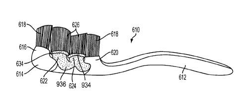
SUMMARY
[13a] According to one aspect of the present invention, there is provided
an
oral care implement comprising: a handle; a head attached to the handle, the
head
having a first face and an opposite second face; a proximal fixed pod and a
distal fixed
pod each extending from the first face, the proximal pod and the distal pod
comprising
a plurality of cleaning elements; a moveable central pod disposed between the
proximal pod and the distal pod, the central pod supported above the first
face by a
suspension member coupled to the proximal pod and distal pod the central pod
comprising a plurality of cleaning elements; and a protruding member extending
from
the first face toward the central pod, wherein said protruding member supports
said
central pod and wherein the protruding member is normally in contact with the
central
pod and the one central pod is pivotable about the protruding member.
[13b] According to another aspect of the present invention, there is
provided an oral care implement comprising: a handle; a head attached to the
handle, the head having a first face; a proximal fixed pod and a distal fixed
pod,
said fixed pods extending from said first face said fixed pods further
comprising a
plurality of cleaning elements; at least one central pod disposed between said
fixed pods and supported above said first face by said fixed pods and by at
least
one resilient suspension member said at least one central pod further
comprising
- 2 -
CA 02649958 2012-02-22
62301-2779
a plurality of cleaning elements; and a protrusion extending from the first
face
toward the central pod, wherein at least a portion of said at least one
central pod
is movable in a direction toward said first face and upon contacting the
protrusion
is moveable in a restrictive pivoting motion.
[13c] According to still another aspect of the present invention, there is
provided an oral care implement comprising: a handle; a head attached to the
handle, the head having a first face; a proximal fixed pod and a distal fixed
pod,
each said fixed pod extending from said first face, said fixed pods further
comprising a plurality of cleaning elements; at least one central pod disposed
between said fixed pods and supported above said first face by said fixed pods
and by at least one suspension member, said at least one central pod further
comprising a plurality of cleaning elements, said suspension member comprising
a
elastomeric hinge, said hinge permitting resilient movement of the at least
one
central pod relative to its suspension connection to the proximal fixed pod
and the
distal fixed pod; and at least one protruding element extending from said
first face
in the direction of said at least one central pod; wherein at least a portion
of said at
least one central pod is movable toward said first face and upon contacting
the
protruding element is moveable in a restrictive pivoting motion.
[13d] According to yet another aspect of the present invention,
there is
provided an oral care implement comprising: a handle; a head attached to the
handle,
the head having a base structure having a first face; a first pod extending
from the
first face of the base structure, the first pod being substantially non-
movable with
respect to the base structure; a second pod extending from the first face of
the base
structure, the second pod being substantially non-movable with respect to the
base
structure; a third pod disposed between and supported above the first face by
the first
and second pods by at least one suspension member, a gap existing between a
bottom surface of the third pod and the first face of the base structure, a
plurality of
cleaning elements extending from the third pod; and a protruding member
extending
from the first face of the base structure, the bottom surface of the third pod
being in
surface contact with the protruding member, said protruding member supporting
said
- 3 -
CA 02649958 2012-02-22
62301-2779
third pod the third pod being pivotable with respect to the base structure
about the
protruding member.
[13e] According to a further aspect of the present invention, there is
provided an oral care implement comprising: a handle; a head attached to the
handle, the head having a base structure having a first face; a first pod
extending
from the first face of the base structure, the first pod being substantially
non-
movable with respect to the base structure; a second pod extending from the
first
face of the base structure, the second pod being substantially non-movable
with
respect to the base structure; a third pod disposed between and supported
above
the first face by the first and second pods by at least one suspension member,
a
gap existing between a bottom surface of the third pod and the first face of
the
base structure, a plurality of cleaning elements extending from the third pod;
the
third pod comprising a housing having a plurality of holes, the plurality of
cleaning
elements extending through the plurality of holes and into the housing,
wherein
bottoms of the plurality of cleaning elements are melted together to form a
mat
that is captured within the housing; and wherein the third pod is movable with
respect to the base structure.
[13f] According to yet a further aspect of the present invention, there is
provided an oral care implement comprising: a handle; a head attached to the
handle, the head having a base structure having a first face; a first pod
extending
from the first face of the base structure, the first pod being substantially
non-
movable with respect to the base structure; a second pod extending from the
first
face of the base structure, the second pod being substantially non-movable
with
respect to the base structure; a third pod disposed between and supported
above
the first face by the first and second pods by at least one suspension member,
a
gap existing between a bottom surface of the third pod and the first face of
the
base structure, a plurality of cleaning elements extending from the third pod;
and
the base structure comprising a hinge section that allows a proximal portion
and a
distal portion of the head to flex relative to one another.
- 3a -
CA 02649958 2012-02-22
62301-2779
[13g] According to another aspect of the present invention, there is
provided an oral care implement comprising: a handle; a head attached to the
handle, the head having a base structure having a first face; a first pod
extending
from the first face of the base structure and comprising a plurality of
cleaning
elements extending from the first pod; a second pod extending from the first
face
of the base structure and comprising a plurality of cleaning elements
extending
from the second pod; and a third pod disposed between the first and second
pods,
the third pod supported above the first face by the first pod, the second pod,
and at
least one suspension member, a gap existing between a bottom surface of the
third pod and the first face of the base structure, a plurality of cleaning
elements
extending from the third pod; wherein a top portion of the first pod, a top
portion of
the second pod, the third pod, and the at least one suspension member are
formed as a unitary assembly that is subsequently attached to the base
structure.
[13h] According to another aspect of the present invention, there is
provided
an oral care implement comprising: a handle; a head attached to the handle,
the
head having a base structure having a first face; a unitary assembly
comprising: a top
portion of a first pod; a top portion of a second pod; a third pod comprising
a plurality
of cleaning elements extending from the third pod; and at least one suspension
member; the unitary assembly attached to the base structure so that: the first
pod
extends from the first face of the base structure; the second pod extends from
the
first face of the base structure; and the third pod is disposed between the
first and
second pods, the third pod is supported above the first face by the first pod,
the
second pod, and at least one suspension member so that a gap exists between a
bottom surface of the third pod and the first face of the base structure.
[13i] According to yet another aspect of the present invention, there is
provided a method of forming an oral care implement having a handle and a head
comprising: a) forming a unitary assembly comprising a top portion of a first
pod, a
top portion of a second pod, a third pod disposed between the top portion of
the first
pod and the top portion of the second pod and comprising a plurality of
cleaning
- 3b -
CA 02649958 2013-07-18
62301-2779
elements extending from the third pod, and at least one suspension member; and
b) attaching the top portion of the first pod and the top portion of the
second pod to a
base structure of the head to form the first pod extending from a first face
of the base
structure and the second pod extending from the first face of the base
structure, such
that the third pod is disposed between the first and second pods, and the
third pod is
supported above the first face by the first pod, the second pod, and at least
one
suspension member so that a gap exists between a bottom surface of the third
pod
and the first face of the base structure.
[13j] According to another aspect of the present invention, there is
provided
an oral care implement, comprising: a handle; a head connected to the handle,
the
head having a base structure; and a plurality of cleaning elements attached to
the
base structure, one end of each of the plurality of cleaning elements being
connected
to one another, wherein at least one of the plurality of cleaning elements is
a spiral
bristle.
[13k] According to another aspect of the present invention, there is
provided
an oral care implement comprising: a handle; a head coupled to the handle, the
head
having a longitudinal axis and a base structure with a front surface; a
cleaning
element carrier supported above the front surface of the base structure so
that a gap
exists between the cleaning element carrier and the base structure, the
cleaning
element carrier comprising a first longitudinal segment and a second
longitudinal
segment that are spaced apart by a longitudinal gap; a plurality of first
cleaning
elements extending from a top surface of the cleaning element carrier; at
least one
second cleaning element extending from the front surface of the base
structure; and
wherein an axis that is transverse to the longitudinal axis of the head
intersects both
the second cleaning element and the cleaning element carrier.
[131] According to another aspect of the present invention, there is
provided
an oral care implement comprising: a handle; a head coupled to the handle, the
head
having a longitudinal axis and a base structure with a front surface; a
cleaning
element carrier having a top surface and a bottom surface, the cleaning
element
- 3c -
CA 02649958 2013-07-18
62301-2779
carrier supported above the front surface of the base structure so that a gap
exists
between the bottom surface of the cleaning element carrier and the front
surface of
the base structure; a plurality of first cleaning elements extending from the
top
surface of the cleaning element carrier; at least one second cleaning element
extending from the front surface of the base structure beyond the top surface
of the
cleaning element carrier; and wherein an axis that is transverse to the
longitudinal
axis of the head intersects both the second cleaning element and the cleaning
element carrier.
[13m] According to another aspect of the present invention, there is
provided
an oral care implement comprising: a handle; a head coupled to the handle, the
head
having a longitudinal axis and a base structure with a front surface; a
cleaning
element carrier supported above the front surface of the base structure so
that a gap
exists between a bottom surface of the cleaning element carrier and the front
surface
of the base structure, the cleaning element carrier comprising a first
longitudinal
segment and a second longitudinal segment that are spaced apart along the
longitudinal axis of the head by a longitudinal gap; a plurality of first
cleaning
elements extending from a top surface of the cleaning element carrier; and at
least
one second cleaning element extending from the front surface of the base
structure
along the longitudinal axis of the head, the at least one second cleaning
element
protruding through the longitudinal gap.
[14] Some aspects of the present invention pertain to an oral care
implement that provides several advantages and that may be used for multiple
functions. In one embodiment of the invention, an oral care implement is
provided
that has a plurality of cleaning elements extending from the head, which are
attached to a support that is flexibly attached to the head. The cleaning
elements
may include forward angled cleaning elements and/or rearward angled cleaning
elements. The cleaning elements may further include a central support at a
central portion of the support.
- 3d -
CA 02649958 2013-07-18
62301-2779
[15] Embodiments of the invention may be multi-functional and include
various combinations of features in advantageous combinations. Some
embodiments include a soft tissue cleaner in combination with tooth cleaning
features and/or in combination with gripping features on the handle that
improve
BRIEF DESCRIPTION OF THE DRAWINGS
[16] A more complete understanding of the present invention and the
advantages thereof may be acquired by referring to the following description
in
- 3e -
CA 02649958 2008-10-20
WO 2007/134026 PCT/US2007/068435
1171 Figure 1 is a perspective view of an embodiment of an oral care implement
such as a
toothbrush in accordance with this invention.
1181 Figure 2 is a side elevational view, in partial section, of the
toothbrush shown in Figure 1.
1191 Figure 3 is a top, plan view of the toothbrush shown in Figures 1 and 2.
1201 Figure 4 is a side elevational view similar to Figure 2 shown partially
broken away.
1211 Figure 5 is a side elevational view showing a subassembly of the bristle
containing
portion of a brush head in accordance with an aspect of the invention.
[22] Figure 6 is a side elevational view, in partial section, showing the
subassembly of Figure
incorporated in a completed toothbrush according to an embodiment of the
invention.
1231 Figure 7 is a perspective view of a head portion of an oral care
implement in accordance
with an embodiment of the invention.
[241 Figure 8 is a side view of the head portion shown in Figure 7,
[25.] Figure 9 is a top view of the head portion shown in Figures 7 and 8.
1261 Figure 10 is a side view of a head portion of an oral care implement in
accordance with
an embodiment of the invention.
1271 Figure 11 is a top view of the head portion shown in Figure 10.
1281 Figure 12 is a top view of a soft tissue cleaner side of an oral care
implement in
accordance with a further embodiment of the invention.
[29] Figure 13 is a partial perspective view of the oral care implement of
Figure 12 without
tooth cleaning elements.
[30] Figure 14 is a top view of an oral care implement in accordance with a
further
embodiment of the invention.
1311 Figure 15 is a partial perspective view of the oral care implement of
Figure 14 without
tooth cleaning elements.
[321 Figure 16 is a partial perspective view of an oral care implement
according to a further
embodiment of the invention without tooth cleaning elements.
- 4 -
CA 02649958 2008-10-20
WO 2007/134026 PCT/US2007/068435
[33] Figure 17 is a top view of an oral care implement in accordance with a
further
embodiment of the invention.
[341 Figure 18 is a partial perspective view of the oral care implement of
Figure 17 without
tooth cleaning elements.
[351 Figure 19 is partial perspective view of an oral care implement according
to an
embodiment of the invention.
[36[ Figure 20 is a side elevational view of the oral care implement of Figure
19.
[37] Figure 21 is a side elevational view of a further embodiment of an oral
care implement.
[38] Figure 22A is a side elevational view of another embodiment of an oral
care implement.
[39] Figure 228 shows the oral care implement of Figure 22A while engaging a
tooth.
[40] Figure 23A is a top view of an oral care implement according to another
embodiment of
the invention.
[411 Figure 23B is a side elevational view of the oral care implement of
Figure 23A.
[42i Figure 24A is a top view of an oral care implement according to another
embodiment of
the invention.
[43] Figure 248 is a side elevational view of the oral care implement of
Figure 24A,
[44] Figure 25A is a top view of a head of an oral care implement according to
another
embodiment of the invention.
[45] Figure 258 is a side elevational view of the oral care implement of
Figure 25A.
[46] Figure 25C is a top view of a head of an oral care implement according to
another
embodiment of the invention.
[47.1 Figure 25D is a side elevational view of the oral care implement of
Figure 25C.
[481 Figure 25E is a top view of a head of an oral care implement according to
another
embodiment of the invention.
[49) Figure 26 is a bottom perspective view of a head of an oral care
implement according to
another embodiment of the invention.
- 5 -
CA 02649958 2008-10-20
WO 2007/134026 PCT/US2007/068435
1501 Figure 27 is a cross-sectional view of the oral care implement of Figure
26.
[511 Figure 28 is a side elevational view of the oral care implement according
to another
embodiment of the invention.
[521 Figure 29 is a bottom perspective view of a head of an oral care
implement according to
another embodiment of the invention.
DETAILED DESCRIPTION OF THE PREFERRED EMBODIMENTS
[531 The following embodiments describe aspects of the invention in the form
of various oral
care implement configurations that provide a variety of features and
functions. Although these
aspects are disclosed in the context of particular exemplary embodiments, the
invention provides
an oral care implement that includes one or more of the features described
herein. The oral care
implement may include a first feature described in one example configuration
herein, as well as a
second feature described in another example configuration herein.
f 54] In other words, the invention contemplates mixing and matching features
from the
disclosed embodiments in various combinations into a single oral care
implement. The present
invention thus makes it possible to select a combination of cleaning element
configurations,
tissue cleaner configurations, handle features, gripping features, mechanical
driving features,
materials and orientations, etc. to achieve intended results, and to deliver
additional oral health
benefits, such as enhanced cleaning, tooth polishing, tooth whitening, tongue
cleaning,
massaging of gums, etc.
[551 The term "cleaning elements" is intended to be used in a generic sense
which could
include elements for cleaning, treating, polishing, whitening, scraping,
scrubbing, etc. Cleaning
elements may include, but are not limited to, nylon or fiber bristles, massage
elements, and
elastorneric fingers or walls arranged in a circular cross-sectional shape or
any type of desired
shape including straight portions or sinusoidal portions. In the form of
bristles, the cleaning
elements may be secured to a flexible membrane or web via in-molded
technology, mounting the
tuft blocks or sections by extending them through suitable openings in the
flexible membrane, or
other mechanisms.
- 6 -
CA 02649958 2011-07-18
62301-2779
[56] A variety of oral care implement configurations are disclosed
herein.
One configuration is an oral care implement having multiple groupings of
cleaning
elements that are uniquely mounted to the head of the oral care implement to
facilitate flexible orientation of some groupings relative to the teeth and
gums being
cleaned. For example, groupings of the head may cooperate to "wrap around"
individual teeth resulting in deeper penetration of cleaning/treating elements
between
teeth. Such configurations can provide effective overall cleaning, for
example, by
independent movement of groups of cleaning elements relative to the head and
each
other. This configuration and others are described below.
[57] Figures 1-4 illustrate a toothbrush 610 in accordance with one
embodiment of this invention. As shown therein toothbrush 610 includes an
elongated handle 612 with a head 614 connected to and extending from the
handle.
The head 614 is divided into a plurality of separate cleaning areas which are
spaced
from each other. As illustrated the cleaning areas include a base 616 located
at the
distal end of the head 614 and projecting outwardly from the main body portion
930
(Figure 4) of the head. Base 616 includes at least one and preferably a
plurality of
cleaning elements 618. Head 614 further includes a base or supporting member
620
at the proximal end of head 614. Cleaning elements 618 also extend outwardly
from
base 620.
[58] Mounted between the cleaning areas that incorporate bases 616 and
620 are a pair of pods 622, 624. Each pod is provided with at least one and
preferably a plurality of cleaning elements 626. As later described the pods
622, 624
have greater degrees of freedom than do the bases 616, 620. In a preferred
practice
of the invention the pods 622, 624 are resilient members so that the pod
cleaning
elements 626 add a motion range beyond the cleaning elements 618 which are
generally static or non-movable. Because the various cleaning elements 618,
626 are
separated from each other such as by channels 728, which extend completely
across
head 614 in a transverse direction, and because of the elastic nature of pods
622,
624, the cleaning elements 626 may be capable of 360 degrees rotation about
the
vertical axis of each individual pod. The angle of the bend may be dictated by
the
ability of the material to bend.
[59] Toothbrush 610 thus provides a head 614 wherein the front
(distal end)
and the back (proximal end) areas are in a relatively fixed position and
wherein the
cleaning/treating elements, such as cleaning elements or bristle strands 618
do not
- 7 -
CA 02649958 2011-07-18
62301-2779
have any extra degree of motion. The middle portion of head 614, however, has
two
areas of cleaning elements 626, which are capable of 360 degree rotation.
[60] As shown in Figure 4, the head 614 includes a main body
portion 930
which supports the bases and pods. Body portion 930 and bases 616 and 620 are
preferably made from conventional hard plastic materials, such as
polypropylene for
example, commonly used in the making of toothbrush handles and heads. Pods
622,
624, however, are made so as to be resilient. In a preferred practice of this
invention,
the resiliency of pods 622, 624 is achieved by providing a thin diameter beam
932
which extends from the main body portion 930 of the head of the toothbrush.
Beam
932 is joined into the bottom of a thin pad or plate 934 which provides a
support area
onto which the cleaning elements 626 are affixed. The manner of mounting the
cleaning elements 626 to the support pads 934 can be achieved utilizing
various
cleaning elements, such as bristles and other cleaning materials, in known
attachment methods.
[61] The desired flexibility or resiliency of the pods 622, 624 is enhanced
by
enclosing the thin beams 932 in elastic material 936 during a multi-injection
molding
process. The elastic material 936 is resilient such that the beams 932 return
toward
their original form or initial position once a brushing stroke force is
removed or
reduced. This return action creates an active motion in the opposite direction
of the
beam bend which aids in the cleaning of teeth by introducing extra brushing
strokes.
[62] As best shown in Figures 1, 2 and 4 the pods 622, 624 include a
widened portion disposed toward the body 930. The support pads 934 are also
widened. Each pod has a narrow or reduced diameter central portion 938
longitudinally intermediate the length of each pod. Thus, each pod is of
generally
mushroom shape.
[63] Beam 932 could be of any suitable shape such as having a cross-
section which is circular, square or any other geometric shape that provides a
thin
dimension or thin diameter to the beam to facilitate the bendability of the
beam. The
elastomer 936 may be considered as a continuous layer of any suitable
thickness
which covers the entire central area of head 614 as illustrated so that both
pods 622,
624 are incorporated as part of the same elastic material. The portion of the
head
614 which includes pods 622, 624 may be formed as a separate subassembly
similar
to the subassembly later described with respect to Figures 5 and 6.
- 8 -
CA 02649958 2011-07-18
62301-2779
[64] Although the invention could be practiced with a single base
and a
single pod and could be practiced with the base having some, but a lesser
degree of
flexibility than the pod, the invention is preferably practiced wherein the
base is
generally static or non-'-movable. In addition, the invention is preferably
practiced
where there are a plurality of such bases and a plurality of pods. The
drawings
illustrate a configuration of the invention where there are a total of four
separate
cleaning areas with the pods being located in the central portion of head 614.
The
invention may be practiced in a configuration in which the cleaning elements
comprise
a plurality of bristles or strands on each base and each pod.
[65] As illustrated in Figures 3 and 4 each base 616 and 620 and each pod
622 and 624 may have a generally oval outer surface. The bases and pods are
longitudinally aligned, but spaced from each other by the depressions or open
areas
which form the channels 728. As also illustrated in Figure 3 the pods may have
a
larger outer surface or cleaning element carrying surface than do the bases.
[66] As shown in Figures 2 and 4 the terminal surfaces of the cleaning
elements 618 and 626 are tapered so that the terminal surfaces of the cleaning
elements 618 taper outwardly in a direction toward the center of head 614
while the
terminal surfaces of cleaning elements 626 taper outwardly in a direction away
from
the center of head 614. Thus, the highest points of each set of cleaning
elements 618
and its adjacent set of cleaning elements 626 are generally disposed toward
each
other for each pair of base and pod 616, 622 and 620, 624.
[67] Any suitable form of cleaning elements may be used as the cleaning
elements 618 and 626 in the broad practice of this invention. The term
"cleaning
elements" is intended to be used in a generic sense as described above. Using
different cleaning materials as cleaning elements of the toothbrushes may
yield
different effects. In an attempt to provide better stain removal, a rubber-
like material
or elastomer can be used in combination with conventional bristles or used by
itself to
"brighten/whiten" the teeth.
[68] It is to be understood that the specific illustration of the cleaning
elements is merely for exemplary purposes. The invention can be practiced with
various combinations of the same or different cleaning element configurations
(such
as stapled, anchor-free tufted (AFT) bristles or in-molded technology (IMT)
bristles,
etc.) and/or with the same bristle or cleaning elements materials (such as
nylon
- 9 -
CA 02649958 2011-07-18
62301-2779
bristles, spiral bristles, rubber bristles, etc.) Similarly, while Figure 2
illustrates the
cleaning elements to be generally perpendicular to the outer surface of head
614,
some or all of the cleaning elements may be angled at various angles with
respect to
the outer surface of head 614. It is thereby possible to select the
combination of
cleaning element configurations, materials and orientations to achieve
specific
intended results to deliver additional oral health benefits, like enhanced
cleaning tooth
polishing, tooth whitening and/or massaging of the gums.
[69] Figures 5-6 illustrate a further embodiment of this invention. The
toothbrush 1110A has the ability to provide flexible support for the bristles
1026A in
designated areas. The flexibility is provided by designing the tuft holding
areas or
plates 1034A as plates, which in combination with the stems 1038A form pods
having
a mushroom shape. The mushroom stem 1038A is made flexible to allow the plate
1034A populated with bristles or cleaning elements 1026A to move in different
directions while brushing, as described with respect to the flexible pods of
Figures 1-4.
[70] Figures 5-6 show the toothbrush 1110A and in particular the cleaning
element or bristle carrying portion 1023 of the head 1114A, which includes a
base
1033. As shown in Figure 5, the bristle or cleaning element carrying portion
1023
forms an initial subassembly. This subassembly is made by introducing the
cleaning
elements 1026A into the mold cavity into which a plastic material is injected.
As the
material injected cools off it permanently traps the bristles or cleaning
elements
1026A to form a brush or subassembly 1023.
[71] To achieve a functional flexibility and proper tuft retention the
portion of
the bristle holding part or subassembly 1023 which comprises the plates 1034A,
stems 1038A and interconnecting support 1025 is preferably a blend of
polypropylene
(PP) and soft TPE. Once the PP/TPE blend is combined with the bristles 1026A
the
subassembly 1023 is formed. The subassembly 1023 is then overmolded with an
entire toothbrush handle 1112A and head 1114A during a second injection cycle
to
form the completed toothbrush 1110A shown in Figure 6. If desired or required
the
entire handle 1112A and head 1114A absent the subassembly 1123 could be made
first and the subassembly or bristle retaining portion 1123 made second. While
an
IMT process has been described, the subassembly could also be formed using an
AFT process, wherein the cleaning elements are fused together and then
captured
within the plates, for example.
- 10-
CA 02649958 2011-07-18
62301-2779
[72] It is to be understood that the invention described in Figures
5-6 could
be practiced where all portions of the head 1114A include the flexible
mushroom
sections without having less flexible base portions such as bases 616 and 620
of
Figures 1-4. Similarly, the subassembly two shot techniques of Figures 5-6
could be
utilized in the embodiment of Figures 1-4 for forming the two or more central
pods as
a single subassembly initially made separate from the remainder of the head
1114A.
The final toothbrush would be made in a second injection molding process
wherein
the subassembly having interconnected pods 622, 624 would be molded to the
handle 612 and head 614 made of more rigid material.
[73] As noted, Figure 2 illustrates the terminal surfaces of the cleaning
elements 618 and 626 to be tapered in an up and down or zigzag manner.
Figures 5-6 show an alternative taper wherein the terminal surfaces of all
four
cleaning elements collectively, form a smooth, gentle, concave shape. If
desired,
other shapes may be used such as a planar shape for the terminal surfaces or a
convex shape as well as the zigzag or up and down shape shown in Figure 2.
Similarly, the terminal ends of the cleaning elements in the Figures 1-4
embodiment,
as well as those of Figures 5-6, could have the various shapes such as zigzag,
convex, concave or planar.
[74] Figures 7-25E show additional embodiments of the invention that
further illustrate the combinability of various aspects, features and
functions disclosed
herein into single oral care implement configurations. Figures 7-25E disclose
oral
care implement configurations that provide a tooth cleaner having separate
groups of
cleaning elements, which may each be mounted on a fixed base or a flexible
pod, and
which may provide a soft tissue cleaner in addition to the tooth cleaner. The
configurations may be powered or manual devices, and the handles may include
gripping features. As such, the oral care implements disclosed in Figures 7-
25E
generally include the aspects discussed along with Figures 1-6 pertaining to
groups of
cleaning elements that may include flexible pods. It is understood that other
features
may used along with these configurations, such as mechanical drive features
discussed in U.S. Patent Nos. 7,845,042 and 7,703,163 (i.e., the heads of the
various
embodiments described herein could be vibrating heads) and tooth cleaning
features
discussed throughout the specification.
[75] Figures 7-9 illustrate a portion of an oral care implement 9910, such
as
a toothbrush, in accordance with another embodiment of the invention. As shown
-11 -
CA 02649958 2011-07-18
62301-2779
therein, toothbrush 9910 includes a head 9914 and a handle 8103. Handle 8103
may
be formed in accordance with the teachings of U.S. Patent No. 7,047,591, filed
July 30, 2004, although other handle configurations may be used, such as
handle
612, 1112A shown in Figures 1-6. Head 9914 is generally the same as head 614
discussed along with Figures 1-6, with the exception of cleaning elements 9918
and
the contoured surface 9940 disposed on an opposite side of the head from the
cleaning elements. Thus, head 9914 generally includes bases 616 and 620 that
respectively support cleaning elements 9942 and 9944 in a substantially static
configuration. Head 9914 also includes pods 622 and 624 disposed between the
bases for respectively supporting cleaning elements 9946 and 9948. As
discussed
along with Figures 1-6, pods 622 and 624 can provide flexible mounts for
cleaning
elements 9946 and 9948 attached thereto, and may permit rotation and/or
oscillation
of the cleaning elements 9946 and 9948.
[76] Figure 7 shows a contoured surface 9940 disposed on an
opposite side
of the head from the cleaning elements. Contoured surface 9940 includes hills
9951
and valleys 9953 to provide a rolling or undulating surface on a rear face of
the head.
Surface 9940 may be relatively smooth for use with massaging oral tissues and,
as
illustrated in Figures 10 and 12-18, the surface may include soft tissue
cleaning
elements for engaging soft oral tissues and provide cleaning benefits thereto.
[77] Figure 9 is top view of head 9914, which shows a configuration of
tooth
cleaning elements 9918. Cleaning elements 9918 may be formed of elastomeric
wall
members, elongate bristle tufts, or other types of cleaning elements, which
are
independently flexible. In this way, the cleaning elements 9918 are able to
provide a
limited and controlled flow of the dentifrice, as well as maintain sufficient
flexibility to
provide improved cleaning of a user's teeth and stimulation of the user's gums
via the
cleaning elements.
[78] Cleaning elements 9918 are oriented for engaging surfaces to
be
cleaned in a generally intended application direction A (see Figure 8), which
is
generally perpendicular to the face of head 9914. Cleaning elements 9918,
however,
include a mixture of cleaning elements that are aligned with (non-angled) and
oblique
to direction A (angled). The arrangement of angled and non-angled cleaning
elements provides effective engagement and cleaning of oral surfaces, which is
further enhanced by the movable pods configuration. The cleaning elements 9946
and 9948 mounted on pods 622 and 624 are adapted to engage a user's teeth,
gums
- 12 -
CA 02649958 2011-07-18
62301-2779
and other surfaces in a various ways that take advantage of their flexible
support
configuration. As such, as shown in Figure 9, cleaning elements 9946 and 9948
include forward elements 9950 angled toward the tip end of the head, and
rearward
elements 9952 angled toward the handle. As shown in Figure 9, the forward and
rearward elements 9950, 9952 are preferably placed on the forward and rearward
sides of their respective pods, and more preferably, are placed in the corner
regions
of the pods 622, 624. Such a location and orientation increases the likelihood
that
elements 9950 and 9952 will initially engage a surface to be cleaned prior to
other
cleaning elements on the respective pod, which encourages the respective pod
to flex
as the remaining cleaning elements thereon are engaging the surface.
[79] For instance, as oral care implement 9910 is moved forward such that
head 9914 leads the toothbrush, forward elements 9950 will initially engage
surfaces
to be cleaned prior to rearward elements 9952 or other cleaning elements (see,
e.g.,
elements 9956) disposed between elements 9950 and 9952. The forward angle of
elements 9950 will encourage pods 622 and 624 to bend rearward when the
forward
elements contact a surface to be cleaned while the toothbrush is moving
forward.
The rearward bending of the pods 622, 624, and their action of springing
forward in
response to the bending, enhances the cleaning effectiveness of the cleaning
elements 9946 and 9948 disposed on the pods. The angled configuration of
elements 9950 and 9952 improves the bending of the pods 622, 624 in comparison
with alternate embodiments wherein the cleaning elements are angled neither
forward
nor rearward.
[80] Cleaning elements 9946 and 9948 of the pods also include non-angled
cleaning elements 9954, which are beneficial for penetrating surfaces to be
cleaned.
In addition, cleaning elements 9946 and 9948 include a pair of bent,
upstanding walls
9956 in a central portion of the pods. Such walls could be formed as a densely
packed bristle tuft by an IMT or AFT process, or such walls could include
elastomeric
elements. Other configurations are contemplated. Each one of the walls in the
pair
9956 has a concave side opposing the concave side of the other wall in the
pair. The
bent configuration and opposed convex sides of upstanding walls 9956 improve
retention of dentifrice therebetween during use of the oral care implement. In
addition, the bent configuration provides a pair of rigid walls, which, in
their central
location of the pod, supports the pod to prevent overflexing of the cleaning
elements
9946, 9948.
- 13-
CA 02649958 2011-07-18
62301-2779
[81] Cleaning elements 9942 and 9944 disposed on static bases 616 and
620 are configured to cooperate with cleaning elements 9946 and 9948 on the
movable pods, as well as to effectively clean oral surfaces. As shown in
Figure 9, the
bases 622, 624 each include a bristle 9960, a series of upstanding walls 9962,
and
angled cleaning elements 9964, 9966. Bristle 9960 is generally a non-angled
column
that effectively penetrates gaps and recesses between oral structures (e.g.,
teeth).
[82] The series of upstanding walls 9962 are arranged to generally form a
concave wall directed toward the remaining cleaning elements. Thus, the
concave
wall 9962 of the front base 616 has its concave side directed rearward toward
the
handle, and the concave wall on the rear base 620 has its concave side
directed
forward toward the remainder of the cleaning elements. In such a
configuration, the
opposing concave walls work in concert to retain dentifrice within the field
of bristles
9918 via their concave shape that cups the dentifrice, as well as via small
gaps
between the upstanding walls that form the concave walls, which reduce the
flow of
dentifrice therebetween. In addition, the upstanding walls 9962 forming the
concave
walls are non-angled cleaning elements that provide support to the head 9914
during
use and resist overflexing of the cleaning elements when excessive downward
force
is applied by the user.
[83] Angled cleaning elements 9964 and 9966 are angled toward the
movable pods 622 and 624 to cooperate with cleaning elements 9946 and 9948
attached thereto for effectively cleaning oral surfaces. As such, rear base
620
includes forward angled elements 9964, and front base 616 includes rearward
angled
elements 9966. Angled cleaning elements 9964 and 9966 are disposed adjacent
the
cleaning elements 9950 and 9952 of the movable pods. Thus, as the pods flex
back
and forth, angled cleaning elements 9950 and 9952 interpose between
corresponding
angled cleaning elements 9964 and 9966. This provides a scissor-like action
that
enhances cleaning effectiveness and avoids interference between opposing
cleaning
elements 9964, 9966 and 9952, 9950 that may limit movement of the pods 622,
624.
[84] The cleaning elements described in connection with the embodiment of
Figures 7-9, as well as the embodiments to follow, are preferably formed using
an
AFT technique as is known in
- 14 -
CA 02649958 2008-10-20
WO 2007/134026 PCT/US2007/068435
the art. This technique facilitates the arrangement of cleaning element
constructions that depart
from the traditional stapled perpendicular tuft. With Afq technology, the
anchored ends of the
cleaning elements are melted together to form a block of cleaning elements,
that can then be
arranged on a head plate with various dimensions, angles and orientations.
Thus, the blocks of
cleaning elements are generally captured within the pod structures, not
embedded in a supporting
medium.
[851 Referring now to Figures 10-13, an oral care implement 10210 is shown in
accordance
with a further embodiment of the invention. As shown therein, oral care
implement 10210
includes a handle 8103, a head 10214 having cleaning elements 10218 attached
thereto on a first
side of the head, and a soft tissue cleaner 10280 disposed on a second side of
the head that is
opposite to the first side, Oral care implement 10210 generally includes the
aspects and features
of oral care implement 9910, except as pertaining to the configuration of
cleaning elements and
the soft tissue cleaning features. Cleaning elements 10218 primarily include
upstanding walls,
which may include an elastomeric element, or may be fanned as a densely packed
bristle tuft by
an IMT or AFT process. Other configurations are contemplated. The upstanding
walls provide
beneficial wiping and polishing of teeth, in addition to cleaning benefits.
Cleaning elements
10218 also include a central columnar cleaning element 10270, which may be a
bristle, for
penetrating oral surfaces. As shown in Figure 10, each central cleaning
element 10270 extends
beyond other cleaning elements proximate thereto on the same pod. In addition,
central cleaning
element has a pointed tip. As such, central cleaning element 10270 effectively
penetrates and
engages oral surfaces and gaps between surfaces.
11861 Similar to the configuration of Figures 4 and 7, and as shown in Figure
11, the tips or
tei mina' ends of cleaning elements 10218 are tapered such that the pods
are respectively
encouraged toward their adjacent static base while engaging surfaces to be
cleaned. Thus, during
use, cleaning elements 9948 are generally biased toward engagement with
cleaning elements
9944 on rear base 620, and cleaning elements 9946 are generally biased toward
engagement with
cleaning elements 9942 on front base 616. This bias can work along with
movement of the pods
that is imparted via engagement of angled cleaning elements with cleaning
surfaces when the
device is being moved. Increasing movement and the flexing of bases 622 and
624 further
enhances the cleaning effectiveness of the oral care implement.
- 15 -
CA 02649958 2011-07-18
62301-2779
[87] The soft tissue cleaner 10280 includes a plurality of projections
10281
extending from a face 10284 on a second side of head 10214, which is generally
opposite from the direction in which tooth cleaning elements 10218 extend.
Soft
tissue cleaner 10280 is disposed on a contoured surface, such as contoured
surface
9940 shown in Figure 7, which includes hills 9950 and valleys 9952 to provide
a
rolling or undulating surface on a second face of the head. Projections 10281
may be
separately molded and glued to the contoured surface or otherwise attached
thereto.
In addition, they may be integrally formed with the head 10214. The
projections could
each be made from a material different from other projections and/or different
from
other parts. Soft materials, such as a TPE or the like, can be fixed to head
10214 to
form the projections. However, a harder material or virtually any known
material used
to make oral care implements may be appropriate for the projections.
[88] Projections 10281 include a plurality of nubs 10282, which extend from
contoured surface 9940 to engage the soft tissue in a user's mouth. The
projections
10281 could have a variety of shapes, patterns, cross-sections,
configurations, etc.,
and the soft tissue cleaner could have a variety of configurations for the
projections.
[89] As shown in Figure 13, nubs 10282 generally cover rear face 10284 in
a cleaner field 10288, which extends from a region opposite the rear base 620
at a
lower portion of the head to a region opposite the front base 616 at a tip
portion of the
head. The nubs 10282 are dispersed in a substantially continuous pattern over
the
cleaner field 10288. The cleaner field 10288 includes hills 10290, proximate
the edge
portions of face 10284, and valleys 10292, disposed between the hills and at a
central
portion of the face. The configuration of hills and valleys enhances the
effectiveness
of the soft tissue cleaner by concentrating the applied force at the hill
portions during
initial contact with a user's soft tissue, which can increase penetration into
the soft
tissue versus a relatively flat configuration. As the user applies additional
force, the
valleys contact the soft tissue to aid in cleaning the soft tissues. If
excessive force is
applied, the valleys help to limit excessive penetration. When the nubs 10282
in the
valley regions 10292 engage the soft tissue, they provide the added benefit of
dislodging debris that is loosened by the deeper penetration of nubs 10282 on
the
hills 10290. Thus, projections on the hills and valleys work in concert to
initially
loosen and then dislodge debris in a user's soft tissue.
[90] Figures 14 and 15 illustrate another embodiment 10610 of an oral care
implement according to the invention. Oral care implement 10610 generally
includes
- 16-
CA 02649958 2011-07-18
62301-2779
the same aspects and features of oral care implement 10210, except with
respect to
the configuration of projections on the soft tissue cleaner 10680. Rather than
having
nubs across the cleaner field, soft tissue cleaner 10680 only includes nubs
10282 on
the hills 10288. Instead, multiple ridges 10294 are disposed in some of the
valley
regions 10290 including a central portion of face 10284. The ridges can be
made
from the same or a different material than the nubs. For instance, the nubs
and
ridges may be made of the same type of elastomer; however, the elastomer for
the
ridges may be more rigid than that for the nubs.
[91] Ridges 10294 have variable lengths that provide variable
levels of soft
tissue engagement during use. As such, longer and shorter ridges can work in
concert to loosen and dislodge debris as the different lengths of ridges
successively
engage portions of soft tissue. Ridges 10294 taper from a wide base region
disposed
proximate the face 10284, to a narrower tip 10696. Thus, increasing levels of
soft
tissue engagement are provided depending on the amount of user force applied.
[92] Figure 16 illustrates another embodiment 10810 of an oral care
implement according to the invention. Oral care implement 10810 generally
includes
the same aspect and features of oral care implement 10610, except with respect
to
the configuration of projections on the soft tissue cleaner 10880. Soft tissue
cleaner
10880 differs from soft tissue cleaner 10680 in that it does not include
ridges 10294.
Thus, soft tissue cleaner includes nubs 10282 that are only located on hills
10288
along the side portions of face 10284. As such, gentle cleaning is provided
via the
nubs located on the hills. The gentle cleaning is beneficial for simultaneous
functionality of the oral care implement, such as when a user cleans his teeth
while
simultaneously engaging soft tissues inside his cheek via soft tissue cleaner
10880.
The gentle engagement can provide pleasant sensory stimulation along with
gentle
cleaning of the soft tissues.
[93] Figures 17 and 18 illustrate another embodiment 10910 of an
oral care
implement according to the invention. Oral care implement 10910 generally
includes
the same aspects and features of oral care implement 10610, except with
respect to
the configuration of projections on the soft tissue cleaner 10980. Soft tissue
cleaner
10980 differs from soft tissue cleaner 10680 in that ridges 10294 are not
provided in
the central portion of face 10284. Ridges 10294' are provided in valleys 10290
disposed between adjacent pairs of hills 10288. In addition, ridges 10294' are
generally smaller than ridges 10294. As such, gentle cleaning is provided,
which,
- 17 -
CA 02649958 2011-07-18
62301-2779
similar to oral care implement 10810, can be beneficial during simultaneous
functionality of the device.
[94] Referring now to Figures 19-20 an oral care implement 12000 is shown
in accordance with a further embodiment of the invention. As shown therein,
oral
care implement 12000 includes a handle 8103, a head 12002 having a frame
12004,
bases or pods 12010, 12020, 12032 and 12034 on a front side of the head,
cleaning
elements 12218 extending from the pods, and a soft tissue cleaner 12280
disposed
on a rear side of the head that is opposite to the front side. Oral care
implement
12000 generally includes the aspects and features of oral care implement 10210
shown in Figures 10-13, except as discussed hereafter. The soft tissue cleaner
12280 is generally the same as soft tissue cleaner 10280. However, various
soft
tissue cleaner configurations may be used, such as, for example, the soft
tissue
cleaners of Figures 14-18.
[95] Oral care implement 12000 shown in Figures 19 and 20 is illustrated as
having four pods: a proximal pod 12010, a distal pod 12020 and two central
pods
12032 and 12034. The proximal and distal pods extend from frame 12004, which
is
on a rear portion of the head. The embodiment shown in Figures 19 and 20
differs
from the embodiments shown in Figures 1-18 in that the central pods 12032 and
12034 are not connected directly to the rear, frame portion of head 12002, but
rather
are suspended between the proximal pod 12010 and the distal pod 12020. The
proximal pod and the distal pod are attached to the frame, whereas the central
pods
are suspended over the frame. As such, the central pods are spaced from the
frame
12004 such that a gap 12050 is disposed therebetween.
[96] Central pods 12032 and 12034 are suspended via bridge supports
12060, which may include a pair of substantially parallel supports 12060
separated by
a gap 12065. A first bridge support extends longitudinally between the
proximal pod
12010 and central pod 12034, and a second pair of bridge supports extends
longitudinally between distal pod 12020 and central pod 12034. In addition, a
bridge
support 12070 extends longitudinally between central pods 12032 and 12034. The
central bridge support 12070 also includes a pair of parallel supports with a
gap
therebetween. Thus, each central pod is supported by a pair of opposite bridge
supports.
[97] While the illustrated embodiment shows pairs of supports 12060 on
each side of each central pod, other configurations are contemplated. For
example,
-18-
CA 02649958 2011-07-18
62301-2779
instead of a pair of supports 12060, a single bridge element may be disposed
between the proximal or distal pod and the adjacent central pod, and between
the two
central pods. Such a single bridge could be wider than each of the individual
pair of
supports 12060 such that the width of the single bridge support generally
equals the
width of the pair of supports plus gap 12065 therebetween.
[98] The central pods 12032 and 12034 generally have greater degrees of
freedom than do the proximal and distal pods. In one configuration, bridge
supports
12060 and 12070 are substantially rigid. Even so, the suspension arrangement
can
provide a moderate amount of flexibility to the central pods. In a preferred,
more
flexible configuration, bridge supports 12060 and 12070 are flexible features
that
permit the cleaning elements extending from the central pods 12032 and 12034
to
have a much larger range of motion than the cleaning elements extending from
the
proximal and distal pods 12010 and 12020, respectively, which are generally
static or
non-movable. The flexible bridge supports may be formed from a resilient
material,
such as a thermoplastic elastomer. Other rubber-like materials may be used,
such as
other thermoplastics, or a thermoplastic urethane, or a plastomer, or any
combination
thereof.
[99] In a flexible configuration, bridge supports 12060 and 12070 are
resilient and allow the central pods to twist about their support axis and/or
move
toward frame 12004 when downward force is applied to the central pods during
use of
the implement. Further, the elastic nature of the bridge supports may permit
the
central pods to return to their original form or initial position when the
force is
decreased. In addition, when the oral care implement is moved in a
longitudinal
direction parallel to the handle 8103, the central pods can deflect
longitudinally as
they engage a surface to be cleaned. The deflection of the central pods in the
longitudinal direction may also be due to the elastic nature of the support
bridges
12060 and 12070. Such return action can create an active motion in the
opposite
direction of the direction of movement, which aids in the cleaning of teeth by
introducing extra brushing strokes.
[100] The distance between the proximal pod 12010 and the distal pod 12020
may be greater than the width of the each of the central pods 12032 and 12034,
and
in the illustrated embodiment of Figure 19 is approximately twice the width of
one of
the central pods. Further, in the illustrated embodiment, the central pods
12032 and
12034 are suspended away from the frame a distance slightly less than the
thickness
-19-
CA 02649958 2011-07-18
62301-2779
of the central pods 12032 and 12034. The length of the support bridges 12060
and
12070 may be significantly less than the length of the central pods 12032 and
12034,
and, in the configuration shown in Figures 19 and 20, is approximately 1/5 the
length
of the central pods. As a result, with two central pods of the configuration
shown in
Figures 19 and 20, the support bridges 12060 and 12070 span less than 25% of
the
total distance between the proximal and distal pods 12010 and 12020,
respectively.
[101] In addition, the configuration shown in Figures 19 and 20 includes a
unitary assembly that forms a top portion of proximal pod 12010, the top of
distal pod
12020, bridge supports 12060 and 12070 and central pods 12032 and 12034. The
unitary assembly may be made from an elastomeric material, such as a soft
thermoplastic elastomer (TPE). Again, other rubber-like materials may be used,
such
as other thermoplastics, or a thermoplastic urethane, or a plastomer, or any
combination thereof. The top portions 12033 and 12035 of the proximal and
distal
pods can be attached to protrusions (not shown) extending from the underlying
head
12002, thereby providing sufficient support and strength to the proximal and
distal
pods 12010 and 12020. The top portions may also be formed as unitary features
along with the frame of the head, such as from a unitary plastic mold. When
formed
as differentiated features, the proximal and distal pods could be formed from
the
same or different materials than the frame, the bridge supports and/or the
central
pods. For instance, the bridge supports and central pods could be made from a
first
thermoplastic material, and the proximal and distal pods could be formed
separately
from a second thermoplastic material, such as polypropylene. In such a
configuration, the bridge supports and the central pods could be made as a
unitary
construction that is welded or adhered to the proximal and distal pods.
Further, the
bridge supports, the central pods, and the top portions of the proximal and
distal pods
could be formed as a unitary member that is attached to the frame.
[102] As discussed with regard to the embodiment shown in Figures 7 and 8,
the cleaning elements 12218 mounted on the central pods can be adapted to
engage
a user's teeth, gums and other surfaces in a various ways that take advantage
of their
flexible support configuration. For instance, as shown in Figures 19 and 20,
the
cleaning elements provided on the central pods can include forward elements
12090
angled toward the tip end of the head, and rearward elements 12092 angled
toward
the handle end. The location and orientation of these forward and rearward
elements
can increase the likelihood such elements will initially engage a surface to
be cleaned
prior to other cleaning elements on the respective pod, thereby encouraging
the
-20-
CA 02649958 2011-07-18
62301-2779
respective pod to flex as the remaining cleaning elements thereon engage the
surface.
[103] As further shown in Figures 19 and 20, cleaning elements 12218 may
include upstanding walls 12094, which may be elastomeric or bristle-based as
discussed above. The upstanding walls can provide beneficial wiping and
polishing of
teeth in addition to cleaning benefits. Cleaning elements 12218 may further
include a
central columnar cleaning element 12270, which may include one or more
bristles for
penetrating oral surfaces. The columnar cleaning elements may extend beyond
other
cleaning elements proximate thereto on the same pod, and they may have a
generally
pointed tip. As such, central cleaning element 12270 can effectively penetrate
and
engage oral surfaces and gaps between surfaces.
[104] The tips or terminal ends of cleaning elements 12218 may be tapered
such that the suspended pods are respectively encouraged toward their adjacent
proximal or distal pod 12020 and 12010, respectively, while engaging surfaces
to be
cleaned. Thus, during use, cleaning elements extending from central pod 12032
may
generally be biased toward engagement with cleaning elements extending from
proximal pod 12010, whereas cleaning elements extending from central pod 12034
may generally be biased toward engagement with cleaning elements extending
from
distal pod 12020. This bias can cooperate with movement of the pods imparted
via
engagement of angled cleaning elements with cleaning surfaces when the device
is
being moved. Increasing movement and the flexing of the suspended central pods
12032 and 12034 further enhances the cleaning effectiveness of the oral care
implement.
[105] Referring now to Figure 21, an oral care implement or toothbrush
13000
is shown that is similar to the embodiment illustrated in Figures 19 and 20
and
generally has the same the aspects and features, except as pertaining to its
central
pod and the configuration of cleaning elements 13218 and its lack of a soft
tissue
cleaner. Toothbrush 13000 includes a handle 8103 and a head 13002 having a
combination of fixed and suspended cleaning elements. Head 13002 includes a
frame 13004, proximal and distal pods 13010 and 13020, and a single central
pod
13050 suspended between the proximal and distal pods. The handle 8103, head
13002 and proximal and distal pods 13010 and 13020 may be formed as a unitary
construction from a thermoplastic, such as polypropylene.
-21-
CA 02649958 2011-07-18
62301-2779
[106] Single central pod 13050 has an elastomeric section 13055 disposed in
a middle portion of the central pod. The elastomeric section is preferably
made from
a resilient material, such as a soft thermoplastic elastomer (TPE), while the
central
pod is preferably made from more rigid material, such as polypropylene. The
central
pod 13050 is held in place by a molded TPE membrane 13070 that connects with
the
proximal and distal pods 13010 and 13020 to form bridge supports 13060. The
membrane 13070 may form a loop that encompasses the pair of fbted proximal and
distal pods 13010 and 13020 and attaches to opposing sides of central pod
13050.
Grooves (not shown) in side portions of the proximal and distal pods, as well
as the
central pod, may receive membrane 13070. In addition, membrane 13070 may be
attached to the pods via an adhesive and/or a melt bond.
[107] Membrane 13070 allows the central pod 13050 to move toward frame
13004 when sufficient force is applied during a cleaning operation. When such
force
is applied to the central pod, opposite halves 13051 and 13053 of the central
pod will
also flex about the elastomeric section 13055. As a result, the two sets of
cleaning
elements 13218 extending from either end of the central pod 13050 can rotate
toward
one another. The central pod 13050 can flex back to its original position when
the
force on the central pod moving it toward the head 13002 diminishes.
[108] Cleaning elements 13218 extending from central pod 13050 are
generally centrally-tapered, which is generally an opposite orientation to the
configuration of cleaning elements shown in Figures 10 and 11 and Figures 19
and
20. The central taper encourages cleaning elements 13218 to penetrate
interproximal
spaces of the user's teeth while applying moderate force to toothbrush 13000
against
their teeth. When the user applies more excessive force to the toothbrush,
central
pod 13050 moves into contact with frame 13004 and causes the central pod to
bend
about elastomeric section 13055 and further engage the interproximal space to
which
the cleaning elements are applied.
[109] Referring now to Figures 22A and 22B, an oral care implement or
toothbrush 13000 is shown that is similar to the embodiment illustrated in
Figure 21
and generally has the same the aspects and features as toothbrush 13000,
except as
pertaining to its frame. As shown, frame 13007 includes a resilient hinge
element
13080 located in a central portion of the frame and traversing its width. The
hinge
element may be formed from a TPE or other resilient material that is more
flexible
than other portions of the frame. The hinge element may also include a reduced
- 22 -
CA 02649958 2011-07-18
62301-2779
thickness region of the frame about which a TPE or other resilient material is
disposed. For instance, a proximal portion 13082 of the frame and a distal
portion
13084 of the frame may be formed from a relatively rigid material, such as a
polypropylene material, and may include a thin neck region (not shown)
disposed
therebetween. The neck region may permit the proximal and distal portion of
the
frame to rotate with respect to each other. A resilient material 13081 (Figure
22B)
may surround the neck to dampen rotation about the neck. The resilient
material may
be adhered to the frame via an adhesive bond, a melt bond or other attachment
mechanism, such as a compression fit about the neck.
[110] Hinge element 13080 permits proximal and distal portions 13082 and
13084 respectively of frame 13004 to rotate with respect to one another during
use.
Thus, head 13002 can generally curl or bend around a surface to be cleaned,
such as
a user's tooth as illustrated in Figure 22B. In addition, hinge element 13080
can
simply improve the overall flexibility of the head for adapting to a variety
of cleaning
features, orientations of use, and applied forces. For instance, as shown in
Figure 22B, hinge element 13080 can permit frame 13007 to flex like a bow. In
another example (not shown), hinge element 13080 can permit the tip portion of
the
head to be flexed rearward, which will encourage central pod 13050 to move
away
from the frame as the bridge supports are stretched taut. As shown, cleaning
elements 13018 are angled along lines C and B with respect to horizontal plane
D.
[111] Referring now to Figures 23A and 23B, an oral care implement
or
toothbrush 13020 is shown that is similar to the embodiment illustrated in
Figure 21
and generally has the same the aspects and features as toothbrush 13000 and
13000', except as pertaining to its central pod, the arrangement of cleaning
elements
13218, and the existence of a soft tissue cleaner 13280 disposed on a rear
side of its
head that is opposite to the front side. The soft tissue cleaner 13280 is
generally the
same as soft tissue cleaners 10280 and 12280 of Figures 10-13 and 19-20
respectively. However, various soft tissue cleaner configurations may be used,
such
as the soft tissue cleaners of Figures 14-18. Toothbrush 13020 includes a
central
pod 13058 that is substantially unitary and lacks elastomeric section 13055 of
toothbrush 13000. Thus, the central pod can provide relatively firm engagement
of
oral features to be cleaned via the larger rigid central pod, while retaining
benefits
provided via its suspended configuration. As such, central pod can adapt to
the
cleaning forces applied to the head by moving fore, aft, sideways and/or
downward
-23-
CA 02649958 2011-07-18
62301-2779
with respect to the frame. However, its relatively large, rigid size can
provide uniform
orientation to a large number of cleaning members 13218 attached thereto.
[112] Cleaning elements 13218 extending from the central pod are similar to
the cleaning elements 12218 of toothbrush 12000 and generally include the same
configuration, aspects and features as cleaning elements 12218 shown in Figure
19.
However, as central pod 13058 is single pod that spans about the same distance
as
central pods 12032 and 12034 of toothbrush 12000 in Figure 19, central pod
13058
includes additional cleaning elements in its central region. As shown in
Figure 23A, a
central columnar cleaning element 13096 is located at a central portion of the
central
pod, which is similar to columnar cleaning elements 12270 of toothbrush 12000.
Columnar cleaning element 13096 cooperates with columnar cleaning elements
13270 to effectively penetrate and engage oral surfaces and gaps between
surfaces
and to transmit downward force to the central pod when excessive cleaning
force is
applied to the cleaning elements. In addition, several radial cleaning
elements 13098
extend from the central columnar cleaning element 13096 in a generally spoke-
like
configuration at a central region of the central pod. Radial cleaning elements
engage
features to be cleaned throughout a central portion of the pod, which provide
a
perimeter structure at side portions of the central pod. The perimeter
structure
enhances engagement of oral features to be cleaned and can assist with
retaining
dentifrice within the cleaning elements of the central pod during use.
[113] Referring now to Figures 24A and 24B, an oral care implement or
toothbrush 14000 is shown that is similar to the embodiment illustrated in
Figure 21
and comprises a handle (not shown) and a head 14002 having a combination of
fixed
and suspended cleaning elements. Head 14002 includes a frame 14004, proximal
and distal pods 14010 and 14020 having cleaning elements 14018, and a single
central pod 14050 suspended between the proximal and distal pods. The handle,
head 14002 and proximal and distal pods 14010 and 14020 may be formed as a
unitary construction from a thermoplastic, such as polypropylene. A soft
tissue
cleaner 14280 is generally the same as soft tissue cleaners 10280 and 12280 of
Figures 10-13 and 19-20 respectively. However, various soft tissue cleaner
configurations may be used, such as the soft tissue cleaners of Figures 14-18.
[114] Central pod 14050 has an elastomeric section 14055 disposed in a
middle portion of the central pod, or more particularly between a pair of pod
segments. The elastomeric section is preferably made from a resilient
material, such
- 24 -
CA 02649958 2011-07-18
62301-2779
as a soft thermoplastic elastomer (TPE), while the central pod is preferably
made
from more rigid material, such as polypropylene. The central pod 14050 is held
in
place by a molded TPE membrane 14070 that connects with the proximal and
distal
pods 14010 and 14020 to form bridge supports 14060. The membrane 14070 may
form a loop that encompasses the pair of fixed proximal and distal pods 14010
and
14020 and attaches to opposing sides of central pod 14050. Grooves (not shown)
in
side portions of the proximal and distal pods, as well as the central pod, may
receive
membrane 14070. In addition, membrane 14070 may be attached to the pods via an
adhesive and/or a melt bond, for example.
[115] The cleaning elements 14218 on the central pod 14050 are similar to
the configuration of the cleaning elements shown in Figures 19 and 20, with
the
exception of a plurality of central, flexible cleaning elements 14270
extending from the
frame 14004 and protruding through one or more openings (not shown) in the
central
pod 14050. Cleaning element 14270 further comprises massaging and/or polishing
elements 14272 on its upper surface. While two cleaning elements 14270 are
shown,
it will be appreciated that only one, or more than two cleaning elements 14270
may
be used as desired. Cleaning element 14270 may be attached to the frame 14004,
or
extend through the frame 14004 from the soft tissue cleaner 14280 on the
opposite
side of the head 14002. If the latter, the cleaning element 14270 may be
molded
simultaneously with the soft tissue cleaner 14280. In either case, a unitary
structure
defined by the membrane 14070 carrying pods 14010, 14020 and 14050, could be
assembled to the base 14004 over the cleaning element(s) 14270. Other methods
of
construction are contemplated.
[116] Membrane 14070 allows the central pod 14050 and cleaning
elements
14218 to move toward frame 14004, guided by the cleaning elements 14270, when
sufficient force is applied during a cleaning operation. Such movement
provides
additional functionality not described before. One such functionality is a
tooth polisher
in the middle of the head that is surrounded by fixed and movable cleaning
elements
14018, 14218 respectively. In addition, the cleaning element 14270 includes
massaging and/or polishing elements 14272 that are at a fixed height relative
to the
head 14004, yet are surrounded by cleaning elements 14218 that recede toward
the
head 14004 under brushing pressure, enabling the cleaning elements 14272 to be
more efficacious during brushing.
- 25 -
CA 02649958 2011-07-18
62301-2779
[117] When brushing pressure force is applied to the central pod 14050,
segments 14051 and 14053 of the central pod 14050, as well as the cleaning
elements 14270, will flex about the elastomeric section 14055. As a result,
the
cleaning elements 14218 extending from either end of the central pod 14050, as
well
as the cleaning elements 14270, can rotate toward one another. The central pod
14050 can flex back to its original position when the force on the central pod
moving it
toward the head 14002 diminishes.
[118] Referring now to Figures 25A-25E, there is shown various head
configurations for an care implement or toothbrush 15000A-C that are similar
to the
embodiment illustrated in Figures 23A and 23B and comprises a handle 8103 and
a
head 15002 having a combination of fixed and suspended cleaning elements. Head
15002 includes a frame 15004, proximal and distal pods 15010 and 15020 having
cleaning elements 15018, and a central pod 15053 defined by pod segments 15051-
15054 (embodiments of Figures 25A through 25D) or pod segments 15055 through
15058 (embodiment of Figure 25E) suspended between the proximal and distal
pods.
The handle 8103, head 15002 and proximal and distal pods 15010 and 15020 may
be
formed as a unitary construction from a thermoplastic, such as polypropylene.
[119] The central pod segments 15051-15058 are held in place by a molded
TPE membrane 15070 that connects with the proximal and distal pods 15010 and
15020 to form bridge supports 15060. The membrane 15070 may form a loop that
encompasses the pair of fixed proximal and distal pods 15010 and 15020 and
central
pod segments 15051-15058, which segments may be separated by a flexible gap
15062 along the longitudinal axis (embodiment of Figures 25A and 25B) or
lateral axis
(embodiment of Figures 25C and 25D) of the head 15002. Alternatively, segments
15055-15058 of the embodiment of Figure 25E may be separated by a flexible gap
15062 along both the longitudinal and lateral axes of the head. Grooves (not
shown)
in the pods may receive membrane 15070. In addition, membrane 15070 may be
attached to the pods via an adhesive and/or a melt bond, for example.
[120] The cleaning elements 15218 on the central pod segments are similar
to the configuration of the cleaning elements shown in Figures 23A and 23B,
with the
exception of a central cleaning element 15270 having polishing ridges 15272
along its
upper surface that protrudes through an opening (not shown) in the membrane
15070. Such cleaning element 15270 functions in a similar manner as cleaning
element 14270 of Figures 24A and 24B, relative to the membrane 15070 and the
-26-
CA 02649958 2011-07-18
62301-2779
central pod segments 15051, 15053 of Figures 25A and 25B. However, because the
central pod segments 15051, 15053 are separated along the longitudinal axis of
the
head 15002 by a gap 15062, such segments 15051, 15053 will tend to rotate away
from the protruding cleaning element 15270, or rotate around the cleaning
element
15270, under brushing pressure, thereby simulating the movement of a bird's
wings,
resulting in increased efficacy and interproximal penetration. A similar
movement is
experienced along the transverse axis with segments 15052, 15054 of Figures
25C
and 25D, and an even more extensive movement is experienced along the
longitudinal and transverse axes with segments 15055-15058 of Figure 25E.
Thus,
cleaning element 15270 provides a central pivot around which pod segments
15051-
15058 can move.
[121] Cleaning element 15270 may be attached to the frame 15004, or
extend through the frame 15004 from a soft tissue cleaner (not shown) on the
opposite side of the head 15002. If the latter, the cleaning element 15270 may
be
molded simultaneously with the soft tissue cleaner. In either case, a unitary
structure
defined by the membrane 15070 carrying pods 15010, 15020 and central pod 15050
segments 15051-15058, could be assembled to the base 15004 over the cleaning
element 15270. Other methods of construction are contemplated.
[122] Referring now to Figures 26 and 27, an oral care implement such as a
toothbrush 16000 comprises a handle 8103 and a head 16002 having a combination
of fixed and suspended cleaning elements. Head 16002 includes a frame 16004,
proximal and distal pods 16010 and 16020 having cleaning elements 16018, and a
central pod 16050 defined by pod segments 16051 and 16053 suspended between
the proximal and distal pods. The handle 8103, head 16002 and proximal and
distal
pods 16010 and 16020 may be formed as a unitary construction from a
thermoplastic,
such as polypropylene.
[123] The central pod segments 16051 and 16053 may be separated by a
bridge 16052 that is preferably flexible and formed from the same material as
a
molded TPE membrane 16070 that connects with the proximal and distal pods
16010
and 16020 to form bridge supports 16060. The membrane 16070 may form a loop
that encompasses the pair of fixed proximal and distal pods 16010 and 16020
and
central pod 16050 including segments 16051 and 16053, which segments may be
separated by flexible gap 16052 along the lateral axis of the head 16002
and/or along
the longitudinal axis as shown in other embodiments (see, for example,
- 27 -
CA 02649958 2011-07-18
62301-2779
Figures 25A-25E). Grooves (not shown) in the pods may receive membrane 16070.
In addition, membrane 16070 may be attached to the pods via an adhesive and/or
a
melt bond, for example.
[124] Proximal and distal pods 16010 and 16020 may be integral with the
head frame 16004, such that the membrane extends around the central portion of
such pods, or the pods may terminate at the edge of the membrane 16070 (see
the
bottom of pod 16050 in FIG. 27) and be attachable to the head frame 16004 by
ultrasonic welding, adhesive or the like. Accordingly, membrane 16070 may
serve as
an outer frame to a plate of cleaning elements included on pods 16010, 16020
and
16050, which plate may be attachable as a single unit to the head frame 16004.
Thus, the pods 16010, 16020 and 16050 may be assembled and manipulated as a
single unit and attachable to the head frame 16004 as a single unit at the
proximal
and distal ends of the head frame 16004.
[125] Figure 27 illustrates the construction of a portion of pod 16050, and
more specifically a portion of pod 16051, wherein the bottoms 16019 of
cleaning
elements 16018 are melted to form a mat 16021, which mat 16021 is captured
between a pod housing 16071 and floor 16054. The mat 16021 prevents the
cleaning
elements 16018 from passing through the tuft holes in the pod housing 16071.
The
floor 16054, for example, could be adhered or welded to the housing 16071,
with the
floor 16054 being at least partially surrounded by the membrane 16070. Thus,
the
cleaning elements 16018 in this embodiment are captured and secured within the
pod
housing 16071 and floor 16054 in a manner known as anchor-free tufting (AFT),
but
such cleaning elements are not rigidly and securely fixed to any particular
support
structure in the manner of a stapled tuft secured within a tuft hole.
[126] The cleaning elements 16018 on the proximal and distal pods 16010
and 16020 may be supported using an AFT process as described above, wherein
they would be captured between the respective pod housing and the head frame,
or
they may be anchored to the pods 16010, 16020 if such pods constitute integral
extensions of the head frame 16004. If they are provided using an AFT process,
the
connection between the pod housing and the head frame would constitute an edge
connection, with the pod housing being welded, for example, to the head frame
along
the periphery of the pod housing to allow for the mat of melted bristle ends
to reside
between the pod housing and the head frame.
- 28 -
CA 02649958 2011-07-18
62301-2779
[127] When brushing with the toothbrush of, for example, FIGS. 22A-22B,
that has a toothbrush head that is comprised of several areas with affixed
cleaning
elements (proximal and distal ends) interconnected with a flexible, central
rubber-like
field, the central area can bottom and touch the head frame below in an
uncontrollable fashion (see FIG. 22B). As a result there may be a clanking
noise, a
significant "slippage/stretching" of the central portion of the flexible field
with an
imbedded block(s) of cleaning elements that may cause a damage either to the
structure or to the user. By incorporating supports that protrude upwards from
the
brush head, the flexible field's movements can be controlled with an intent to
enable
the flexible field to move in a particular fashion relative to the brush head.
[128] Figures 26 and 27 illustrate one example of a single, central
protrusion
16270 extending from a soft tissue cleaner 16280 on the back of the head 16002
to
an optional depression or notch 16055 provided in the floor 16054 of the tuft
block
16071. As shown in Figure 27, the central protrusion 16270 may have a rounded
head in contact with at least one central pod. Such protrusion 16270 is
preferably
formed or unitarily molded together with the soft tissue cleaner 16280 of a
flexible
material, although it does not have to be, and provides a pivot point for pod
16050.
This enables pod 16050 to move in a controlled fashion relative to the head
frame
16004. Depending on the flexibility of the protrusion 16270, pod 16050 may
also be
capable of normal movement or movement toward the head frame 16004 (again, see
Figure 22B for example). Alternatively, the protrusion 16270 may be rigid and
extend
from the head frame 16004 to provide a rigid pivot point that resists normal
movement
of the pod 16050 toward the center of the head frame 16004, while permitting a
pivoting or rocking motion about the pivot. Of course, while a single, central
protrusion 16270 is illustrated in Figures 26 and 27, the number and type of
protrusions or supports may vary as shown in, but not limited to, Figure 28
(multiple
supports 17270 and 17271 extending between head frame 17004 and central pod
17050) and Figure 29 (transverse bar support 18270 extending from the head
frame
18004 along the transverse axis of the central pod 18050 of toothbrush 18000,
making line contact with the central pod 18050). Each of the embodiments of
Figures 26-29 enables unique movement of the flexible pod relative to the head
frame, with the structure illustrated in Figures 26-27 enabling at least a 360
degree
pivot, the structure illustrated in Figure 28 enabling a more restrictive
pivoting
movement, and the structure illustrated in Figure 29 enabling a rocking
movement
over protrusion 18270.
-29-
CA 02649958 2008-10-20
WO 2007/134026 PCT/US2007/068435
11291 As various changes could be made in the above without departing from the
scope of the
invention, it is intended that all matter contained in this application,
including all mechanisms
and/or modes of interaction described above, shall be interpreted as
illustrative only and not
limiting in any way the scope of the appended claims. Further, as noted above,
it is intended that
oral care implements according to the invention and associated methods may
utilize various
combinations of aspects, features and configurations discussed within the
application.
- 30-