Note: Descriptions are shown in the official language in which they were submitted.
CA 02650106 2010-03-23
H-959-1-CA REPLACEMENT SHEET
A METHOD AND APPARATUS FOR POST-MOLD COOLING A MOLDED ARTICLE
TECHNICAL FIELD
The present invention generally relates to, but is not limited to a method,
molding machine, and
computer-readable product for post-mold cooling a molded article, comprising
balancing cooling
rates between portions of the molded article to substantially reduce post-mold
cooling related
defects of the molded article, amongst other things.
BACKGROUND
Some injection molded articles, for example plastic preforms of the variety
that are for blow
molding into beverage bottles, require extended cooling periods to solidify
into substantially
defect-free molded articles. To the extent that the cooling of the molded
article can be effected
outside of the injection mold by one or more post-mold devices then the
productivity of the
injection mold may be increased (i.e. lower cycle time). A variety of such
post-mold devices,
and related methods, are known and have proven effective at the optimization
of the injection
molding machine cycle time.
In a typical injection molding system, such as the system 10 depicted with
reference to FIG. 1,
and as generally described in commonly assigned United States patent 6,171,541
(Inventor:
NETER, Witold, et al.; Published: 9th January, 2001), just-molded, and hence
partially cooled,
molded articles 2 are ejected from the mold half 8, when the mold halves 8, 9
are spaced apart,
and into holders 50 (i.e. commonly known as a cooling holder, a take-off
holder, or a cooling
pipe, amongst others). The holders 50 are arranged on a post-mold device 15
(i.e. commonly
known as an end-of-arm-tool, carrier plate assembly, removal device, post-
cooling apparatus,
amongst others), the post-mold device 15 configured to cyclically position the
holders 50,
arranged on a supporting plate 16, between an in-mold position between the
mold halves 8, 9, to
receive the molded articles 2, and an out-board position, as depicted, to
allow the mold halves 8,
9 to close and begin another molding cycle. The construction and operation of
the post-mold
device 15, including those having multiple-positions, is generally described
in commonly
assigned United States patent RE33,237 (Inventor: DEFLER, Frank; Published:
19th June, 1990).
Preferably, the molded articles 2 are held in the holders 50 until the molded
articles 2 have
cooled sufficiently that they may be ejected without risk of further
deformation. The injection
molding machine includes a controller 30, such as that described in commonly
assigned United
States patent 6,275,741 (Inventor: CHOI, Christopher; Published: 14th August,
2001), for
controlling machine-control functions.
1
CA 02650106 2010-03-23
H-959-1-CA REPLACEMENT SHEET
The cooling of the molded articles 2 may be assisted by the use of pins 14 for
expelling a
cooling fluid onto an inner portion of the molded articles 2, as shown with
further reference to
FIG. 2B. The pins 14 are arranged on another post-mold device 12 (i.e.
commonly known as a
COOLJET, a trademark of Husky Injection Molding Systems Ltd.), the post-mold
device 12
arranged to be cyclically positioned between a cooling position, with the pins
14 positioned
adjacent the portion of the molded articles 2, and an out-board position, as
depicted. It is also
known to use the molded article post-mold device 12 to extract the molded
articles 2 from the
holders 50 for a re-handling thereof, for instance, to a conveyor.
A portion of the post-mold device 15 depicting a holder 50 arranged on the
supporting plate 16
is shown with reference to FIGS. 2A and 2B. The holder 50 is configured in
accordance with the
general teachings of commonly assigned United States patent 4,729,732
(Inventor: SCHAD, et
al.; Published: 4th March, 1988). In particular, the holder 50 includes a
tapered surface 52
defining a cavity for receiving a portion of the molded article 2, the surface
52 being smaller
than the heated molded article. The holder includes a cooling structure
operative to shrink the
molded article, upon cooling, with the molded article sliding inside the
cavity to fit snugly
therein. The holder 50 further includes a suction structure adjacent a closed
end of the cavity for
maintaining the molded article in the holder 50.
As shown with reference to FIG. 2B, the cooling of the molded articles 2 may
be assisted by the
use of a coolant dispersion device 19 of a post-mold device 13 for dispersion
of a coolant, such
as cool air, around an exposed outer portion of the molded article; as
generally described in
commonly assigned United States patent 6,802,705 (Inventor: BRAND, Tiemo, et
al.; Published:
12th October, 2004).
FIG. 2A depicts an initial position of the molded article 2 in the holder 50
immediately after
having been received from the mold.
FIG. 2B depicts a completely seated position of the molded article 2 in the
holder 50 after
cooling, and related shrinkage, of the molded article 2.
The holder 50 comprises a holder 60 and an insert 70. The insert 70 is
arranged in the holder 60
to provide the closed end of the cavity. The suction structure comprises a
pressure channel 54
that extends through the insert 70, the channel 54 is connectable to an air
pressure source 18,
2
CA 02650106 2010-03-23
H-959-1-CA REPLACEMENT SHEET
provided in a plate 16 of the post-mold device 15, via a pressure channel 18'
configured in the
holder 60. Likewise, the cooling structure comprises a coolant channel 62
configured around the
holder 60, and enclosed by a holder sleeve 64, the coolant channel 62
connectable to a coolant
source 17, provided in the plate 16, via a coolant channel 17' in the plate
16. The holder 60 and
the insert 70 are held on the plate 16 by a fastener 72.
The coolant source 17 in the plate 16 is typically directly connected to a
plant-wide coolant
source. Typical plant-wide coolant sources include a chiller or a cooling
tower to remove the
heat added to the coolant from the molded article in the holder. Presently,
faced with the
problem of improving the efficiency of a molding cycle the common general
knowledge in the
molding art is to remove heat from the molded article holder as quickly as
possible. The coolant,
typically water, is preferably cooled to a temperature in the range of 6-10 C.
In some high
humidity molding environments the coolant may be kept warmer to avoid unwanted
water
condensation on the holder 50.
As can be seen with reference to FIGS. 2A and 2B, a first portion of the
molded article 2' that is
received in the cooled holder 50 will be cooled, by the holder 50, at a first
rate while a second
portion of the molded article 2" that is outside of the holder 50 will be
cooled at a second rate.
Under certain circumstances the second portion of the molded article 2" can
take longer to cool
than the first portion of the molded article 2'. The relative cooling between
the first and second
portions of the molded article 2', 2" may be affected by one or more variables
such as the
distribution of plastic in the molded article 2, the thermal profile of the
molded article when
ejected from the mold 8, 9, the relative first and second rates of cooling,
amongst others.
Whenever the time required for post-mold cooling the second portion of the
molded article 2" is
the limiting factor there is the risk that the first portion of the molded
article 2' may become
over-cooled. An over-cooled first portion of the molded article 2' is prone to
deform.
Problems associated with cooling molded articles in the holder 50 may include
localized sink
marks and ovality.
With the relatively long molding cycle-times of the past it was generally
possible to adjust the
geometry of the cavity in the holder 50 to address the known defects. For
instance, ovality
defects may be addressed by adjusting the cavity in the holder 50 to be
slightly smaller.
3
CA 02650106 2010-03-23
H-959-1-CA REPLACEMENT SHEET
With increasingly aggressive molding cycle-time it is not always possible to
address the defects
by simple adjustment of the cavity geometry in the holder as adjusting the
geometry for one
defect may have the effect of making the another defect more prominent.
SUMMARY
According to a first broad aspect of the present invention, there is provided
a method of post-
mold cooling of a molded article. The method comprises balancing cooling rates
during the post-
mold cooling so that the molded article reaches a target exit temperature at a
point of time that
substantially coincides with a point of time when the molded article is
removed from the post-
mold cooling. In some implementations, the balancing comprises controlling
cooling rates at a
first post-mold cooling portion and a second post-mold cooling portion. In
other
implementations, the balancing comprises balancing cooling rates between
portions of the
molded article.
According to another broad aspect of the present invention, there is provided
a computer-
readable product for use with a controller, which comprises a computer
readable medium
embodying one or more instructions executable by the controller, the one or
more instructions
including: controller executable instructions for instructing a post-mold
device for balancing
cooling rates during the post-mold cooling so that the molded article reaches
a target exit
temperature at a point of time that substantially coincides with a point of
time when the molded
article is removed from the post-mold cooling.
According to another broad aspect of the present invention, there is provided
a molding machine.
The molding machine comprises a post-mold device for cooling a portion of a
molded article;
and a temperature control device for controlling the cooling rate imposed on
the portions of the
molded article by one or more post-mold devices to effect the balancing of the
cooling rates
between the portions.
According to another broad aspect of the present invention, there is provided
a molding machine.
The molding machine comprises a post-mold device for cooling a molded article;
and a
temperature control device for controlling the cooling rate imposed by the
post-mold device.
According to yet another broad aspect of the present invention, there is
provided a method for
post-mold cooling a molded article. The method comprises balancing cooling
rates between
portions of the molded article.
4
CA 02650106 2010-03-23
H-959-1-CA REPLACEMENT SHEET
DESCRIPTION OF THE DRAWINGS
A better understanding of the exemplary embodiments of the present invention
(including
alternatives and/or variations thereof) may be obtained with reference to the
detailed description
of the exemplary embodiments along with the following drawings, in which:
FIG. 1 is a top elevation view of a known injection molding system;
FIG. 2A is a section view through a post-mold device depicted in the injection
molding
system of FIG. I at a time before the molded article has completely seated
therein;
FIG. 2B is a section view through a post-mold device depicted in the injection
molding
system of FIG. 1 at a time after the molded article has completely seated
therein;
FIG. 3 is a top elevation view of an injection molding system in accordance
with a non-
limiting embodiment of the present invention;
FIG. 4 is a top elevation view of an injection molding system in accordance
with another
non-limiting embodiment of the present invention.
The drawings are not necessarily to scale and are may be illustrated by
phantom lines,
diagrammatic representations and fragmentary views. In certain instances,
details that are not
necessary for an understanding of the exemplary embodiments or that render
other details
difficult to perceive may have been omitted.
DETAILED DESCRIPTION OF EMBODIMENTS
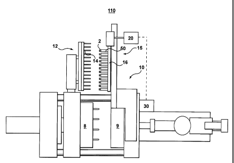
FIG. 3 is an injection molding system 110 in accordance with a non-limiting
embodiment of the
present invention. The molding system 110 is similar to the known molding
system 10 described
hereinbefore which included the post-mold devices 12, 15. The molding system
110 further
includes a temperature control device 20 for controlling the temperature of
the holder 50, on
post-mold device 15, to avoid imparting cooling related defects to the molded
article 2.
The method in accordance with an embodiment of the present invention includes
balancing
cooling rates between the portions 2', 2", 2"' of the molded article 2, as
shown with reference to
FIG. 2B, to substantially reduce post-mold cooling related defects of the
molded article.
5
CA 02650106 2010-03-23
H-959-1-CA REPLACEMENT SHEET
The balancing of the cooling rates between portions 2', 2", 2"' is preferably
controlled such that
each of the portions of the molded article 2', 2", 2"' arrive at respective
ejection temperatures,
that substantially precludes post-ejection defects, at the substantially the
same time.
The method preferably includes controlling the cooling rate imposed on one or
more of the
portions of the molded article 2', 2", 2"' by one or more post-mold devices
12, 13, 15 to effect the
balancing of the cooling rates between the portions 2', 2", 2"'.
In accordance with an embodiment of the present invention the method includes
arranging a first
portion of the molded article 2' in a holder 50 of a post-mold device 15 and
controlling the
temperature of the holder 50 to avoid imparting cooling related defects to the
molded article (2).
Preferably, the controlling of the temperature of the holder 50 minimizes a
temperature
differential in the molded article 2 at a transition between the first portion
of the molded article
2' arranged in the holder 50 and a second portion of the molded article 2"
that is outside of the
holder 50.
Preferably, controlling the temperature of the holder 50 includes controlling
the temperature of a
coolant media that is circulated for controlling the temperature of the holder
50. The temperature
control of the coolant media may be performed by circulating the coolant media
through the
temperature control device 20.
Alternatively, the controlling the temperature of the holder 50 includes the
controlling the flow
rate of a coolant that is circulated to control the temperature of the holder
50.
Preferably, controlling the temperature of the holder 50 includes selecting a
temperature of the
holder 50 whereby the first and second portions of the molded article 2', 2"'
are controllably
cooled at first and second cooling rates such that the molded article portions
2', 2"' arrive at
ejection safe temperatures at substantially the same time.
A technical effect of the embodiment of the present invention is a reduction
in the formation of
defects in the molded article 2 that are related to post-mold cooling of the
molded article.
In accordance with the embodiment of the present invention, the technical
effect was prominent
when the temperature of the coolant media for cooling of the holder 50 was
heated above
6
CA 02650106 2010-03-23
H-959-1-CA REPLACEMENT SHEET
ambient temperature and below a glass temperature of a resin used to form the
molded article 2.
More preferably, the temperature of the holder 50 is selected to be between
about 35 C and
65 C. More preferably still the temperature of the holder 50 is selected to be
about 50 C.
Preferably, the temperature of the holder 50 is homogenous. Alternatively, a
subtle gradient
along the molded article may be useful to reduce local defects, such as sink
marks, while still
avoiding ovality defects.
Preferably, the molding machine controller 30 controls the temperature control
device 20 for
controlling the temperature of the coolant media using closed-loop control.
Alternatively, the
temperature control may be open-loop control. Alternatively, the temperature
control device 20
may include a dedicated controller, not shown, the dedicated controller may be
operatively
linked or entirely independent from the machine controller 30. Accordingly,
the method of
controlling the temperature of the coolant media may further include the
sending coolant
temperature set-points from a molding machine controller 30 to the dedicated
controller in the
temperature control device 20. In addition, operational feedback from the
temperature control
device 20 may be shared with the molding machine controller 30.
In accordance with an alternative embodiment of the invention, the cooling
rate of one or both or
the molded article portions (2", 2"') may be effected similarly by controlling
the post-mold
devices 13, 15. For example, the coolant flow rate, or coolant temperature may
be controlled
through the pin 14 and/or dispersion device 19 of post-mold devices 12, 13.
Any type of controller or processor may be used to balance the cooling rates
between portions
(2', 2", 2"') of the molded article (2), as described above. For example, one
or more general-
purpose computers, Application Specific Integrated Circuits (ASICs), Digital
Signal Processors
(DSPs), gate arrays, analog circuits, dedicated digital and/or analog
processors, hard-wired
circuits, etc., may receive input from the feedback signals described herein.
Instructions for
controlling the one or more of such controllers or processors may be stored in
any desirable
computer-readable medium and/or data structure, such floppy diskettes, hard
drives, CD-
ROMs, RAMs, EEPROMs, magnetic media, optical media, magneto-optical media,
etc. An
expert system may be implemented in the controller 30 to automatically control
the post-mold
devices 12, 13, 15 to adjust the cooling rates of the portions (2', 2", 2"')
based upon quantitative
and/or qualitative feedback on the state of the molded article 2.
7
CA 02650106 2010-03-23
H-959-1-CA REPLACEMENT SHEET
With reference to Figure 4, another non-limiting embodiment of a molding
system 110' will now
be described in greater detail. The molding system 110' can be substantially
similar to the
above-described molding system 110, but for the specific differences to be
discussed herein
below and, as such, like elements are denoted with like numerals. Within these
non-limiting
embodiments of the present invention,. the,molding system 110' comprises a
sensor 402
associated with the post-mold device 15.
Generally speaking, the purpose of the sensor 402 is to determine temperature
associated with
operation of the holders 50. It should be expressly understood that in some
embodiments of the
present invention, the sensor 402 is configured to measure the temperature,
however in other
embodiments, the sensor 402 can measure another parameter which can then be
used to
determine a temperature value. Examples of such a proxy value of an
operational parameter that
can be used include, but are not limited to, pressure exerted by a preform 2
against a wall of the
holder 50 and the like. In some embodiments of the present invention, the
sensor 402 can be
implemented as a thermocouple. In other embodiments of the present invention,
the sensor 402
can be implemented as a thermistor. In yet other embodiments of the present
invention, the
sensor 402 can be implemented as a thermal emission camera (ex. an infrared
camera and the
like). In yet further non-limiting embodiments, the sensor 402 can be
implemented as a pressure
measurement device (ex. a pressure transducer and the like). Other alternative
implementations
are, of course, possible.
In some embodiments of the present invention, the sensor 402 can comprise a
single sensor 402
associated with the post-mold device 15. In other embodiments of the present
invention, the
sensor 402 can comprise a plurality of sensors 402; each of the plurality of
sensors 402 being
associated with a respective holder 50. In alternative non-limiting
embodiments of the present
invention, which are particularly applicable in those implementations where
the post mold
devices 12, 15 are configured to implement a so-called multi-position post-
mold cooling
function, the sensor 402 can comprise a plurality of sensors 402; each of the
plurality of sensors
402 being associated with a selected one of the holders 50 in a given position
of the post-mold
cooling cycle. In other words, the sensor 402 can comprise a plurality of
sensors 402; each of the
plurality of sensors associated with a given position of the post-mold cooling
function. For
example, in a molding system 110' which implements a three-position post-mold
cooling
function, three instances of the sensors 402 can be used.
8
CA 02650106 2010-03-23
H-959-1-CA REPLACEMENT SHEET
The sensor 402 is configured to generate a signal 403 representative of an
operational parameter
(such as the temperature or the like), associated with operation of the
holders 50.
The sensor 402 is coupled to the controller 30 via a communication link 404.
In some
embodiments of the present invention, the communication link 404 can be
implemented as a
wired link. As will be appreciated by those of skill in the art, within these
embodiments of the
present invention, the wired link is configured to withstand operating
temperatures associated
with the molding system 110'. In other non-limiting embodiments of the present
invention, the
communication link 404 can be implemented as a wireless link. Those skilled in
the art will
appreciate that a plethora of possible wireless communication protocols can be
used. Examples
of wireless communication protocols that can be used include, but are not
limited to, Wi-FI
(trade-mark), BLUETOOTH (trade-mark), Wi-Max and the like. The sensor 402 is
operable to
transmit the signal 403 to the controller 30 via the communication link 404.
Naturally, in
alternative non-limiting embodiments of the present invention, the sensor 402
can be coupled to
a dedicated controller (not depicted) separate from the controller 30.
How the sensor 402 generates and transmits the signal 403 is not particularly
limited. For
example, the sensor 402 can sense an operating parameter, generate the signal
403 representative
of the sensed operating parameter and to transmit the signal 403 to the
controller 30 at regular
time intervals. In other non-limiting embodiments of the present invention,
the sensor 402 can
sense an operating parameter, generate the signal 403 representative of the
sensed operating
parameter and to transmit the signal 403 to the controller 30 at a beginning
of a given position of
the post-mold cooling cycle. For example, within a four-position post-mold
cooling cycle, the
sensor 402 can repeat this routine at a beginning of each of the four-
positions of the post-mold
cooling cycle.
Alternatively, the sensor 402 can perform a similar routine at a beginning of
a first position of a
multi-position post-mold cooling cycle. In yet further non-limiting
embodiments, the sensor 402
can perform the same routine upon receipt of a request signal (not depicted)
from the controller
30.
Given the architecture of Figure 4, it is possible to implement a method for
post-mold cooling
according to another non-limiting embodiment of the present invention.
9
CA 02650106 2010-03-23
H-959-1-CA REPLACEMENT SHEET
At a first instance in time, i.e. at a beginning of a post-mold cooling cycle,
a molded article 2 is
received within the holder 50 and a first portion of the post-mold cooling
cycle begins. Within
the first portion of the post-mold cooling cycle, the temperature control
device 20 controls the
coolant media that is circulated for controlling the temperature of the holder
50 to a first cooling
temperature. As a non-limiting example and not as a limitation, the first
cooling temperature can
be 10C .
At a second instance in time, i.e. at some point in time after the first
instance in time, a second
portion of the post-mold cooling cycle commences. Within the second portion of
the post-mold
cooling cycle, the temperature control device 20 controls the temperature of
the coolant media
that is circulated for controlling the temperature of the holder 50 to a
second cooling
temperature, which is greater then the first cooling temperature. As a non-
limiting example and
not as a limitation, the second cooling temperature can be 65C .
A point in time when the first post-mold cooling portion ends and the second
post-mold cooling
portion commences, can be broadly called a switch point. How the switch point
is determined is
not particularly limited and can be implemented in several possible
alternatives.
Pre-determined point in time
In some embodiments of the present invention, the switch point can be
implemented as a
pre-determined point in time. For example, an operator operating the molding
system
110' can set-up the switch point using, for example, a human-machine interface
(not
depicted) of the molding system 110'. This switch point can be expressed as a
value
representative of time elapsed since a beginning of a post-mold cooling cycle
(ex. 2
seconds, 3 seconds, 4 seconds, 5 seconds or any other suitable value).
Alternatively, this
switch point can be expressed as a value representative of number of positions
of the
post-mold cooling cycle expired after a beginning of the post-mold cooling
cycle (ex. a
switch point after 1 position is completed, 2 positions are completed, 3
positions are
completed, 4 positions are completed, 2.5 positions are completed, 3.2
positions are
completed and the like). Alternatively, a combination of the number of
positions and
elapsed time since the beginning of the last position can be used (ex. 2
positions and 1
second, etc.).
Within these embodiments of the present invention, the switch point can be
adjusted
from time to time. For example, the operator can change the switch point
using, for
CA 02650106 2010-03-23
H-959-1-CA REPLACEMENT SHEET
example, the human-machine interface (not depicted) to move the switch point
closer or
further way from the beginning of the post mold cooling cycle.
Temperature value
In alternative non-limiting embodiments of the present invention, the switch
point can be
implemented as a temperature value associated with operation of the holders 50
(i.e. a
target temperature). For example, the switch point can be expressed as a
temperature
value associated with molded articles 2 being treated in a given position of
the post-mold
cooling cycle or a holder 50. As an example and not as a limitation, the
switch point can
be expressed as 65C . In other words, when the molded article 2 reaches the
temperature
of 65C , a switch between the first post-mold cooling portion and the second
post-mold
cooling portion occurs.
Within these embodiments of the present invention, the controller 30 monitors
the
signal(s) 403 received from the sensor 402 or the plurality of sensors 402.
When a given
signal 403 is indicative of a given molded article 2 reaching the target
temperature, a
determination is made that the switch point has been reached.
In those embodiments of the present invention, where the sensor 402 is
implemented as a
plurality of sensors 402; each of the plurality of sensors being associated
with a given
holder 50; the controller 30 receives a plurality of signals 403 from each of
the plurality
of sensors 402. The controller 30 then individually analyzes each of the
plurality of
signals 403.
In those embodiments of the present invention, where the sensor 402 is
implemented as a
plurality of sensors 402; each of the plurality of sensors being associated
with a given
position of the post-mold cooling function; the controller 30 receives a
plurality of
signals 403 from each of the plurality of sensors 402. The controller 30 then
individually
analyzes each of the plurality of signals 403 for a given position of the post-
mold cooling
cycle. Within these embodiments of the present invention, an assumption is
made that
molded articles 2 being treated within the same position of the post-mold
cooling cycle
have substantially the same temperature.
In those embodiments of the present invention, where the sensor 402 is
implemented as a
single sensor, the controller 30 receives a single signal 403 from the single
sensors 402.
11
CA 02650106 2010-03-23
H-959-1-CA REPLACEMENT SHEET
The controller 30 then analyzes the single signal 403 and performs a
calculation routine
to determine a respective temperature associated with each position of the
multi-position
post-mold cooling cycle.
The temperature control of the coolant media may be performed by circulating
the coolant media
through the temperature control device 20. How the temperature control device
20 controls the
coolant media is not particularly limited. In some embodiments of the present
invention, the
temperature control device 20 can control the coolant media by heating and/or
cooling the
coolant media. In alternative non-limiting embodiments, the temperature
control device 20 can
control the coolant media by controlling a rate of flow of the coolant media.
In yet further non-
limiting embodiments of the present invention, the temperature control device
20 can control the
coolant media by shutting off supply of the coolant media at the second post-
mold cooling
portion. Other alternatives are, of course, also possible. Yet in further non-
limiting embodiments
of the present invention, the temperature control device 20 can control the
coolant media by
changing the coolant media from a first type of coolant media to a second type
of coolant media.
Other alternatives are, of course, also possible.
Accordingly, it should now become apparent that the method of controlling post-
mold cooling
broadly includes steps of balancing cooling rates during a post-mold cooling
function. More
specifically, the balancing of cooling rates may include balancing of cooling
rates among various
portions 2', 2", 2"' of the molded article 2. Balancing of cooling rates may
be further
implemented using two methods of various embodiments of the present invention:
(a) increasing the initial cooling rate (for example, by increasing the
cooling
temperature) to ensure that the various portions 2', 2", 2"' of the molded
article 2
reach a target exit temperature at substantially the same time. In some
embodiments of the present invention, this substantially same time
substantially
coincide with an instance of time when the molded article 2 is ready for
ejection
from the post-mod device 15. In other words, the balancing may include
controlling an initial cooling rate to decrease a temperature differential
between a
just-molded article 2 and cooling media
(b) Initially cooling the molded article 2 at a first temperature, then at a
switch point
commencing cooling at a second temperature; to ensure that the various
portions
2', 2", 2"' of the molded article 2 reach the target exit temperature at
substantially
12
CA 02650106 2010-03-23
H-959-1-CA REPLACEMENT SHEET
the same time. In some embodiments of the present invention, this
substantially
same time substantially coincide with an instance of time when the molded
article
2 is ready for ejection from the post-mod device 15.
Accordingly, a technical effect of some embodiments of the present invention
leads to reduced
slow-cooling induced defects (ex. crystallinity, ovality, etc.). Another
technical effect of the
embodiments of the present invention is that the molded article 2 reaches a
target exit
temperature at a point of time that substantially coincides with a point in
time when the molded
article 2 is removed from the post-mold device 15.
The description of the embodiments provides examples of the present invention,
and these
examples do not limit the scope of the present invention. For example,
balancing of cooling
rates will be specific to both molded article (e.g. preform) design and
molding cycle time. It is
understood that the scope of the present invention is limited by the claims.
The concepts
described above may be adapted for specific conditions and/or functions, and
may be further
extended to a variety of other applications that are within the scope of the
present invention.
Having thus described the exemplary embodiments, it will be apparent that
modifications and
enhancements are possible without departing from the concepts as described.
Therefore, what is
to be protected by way of letters patent are limited only by the scope of the
following claims:
13