Note: Descriptions are shown in the official language in which they were submitted.
CA 02650134 2008-10-22
WO 2007/125283 PCT/GB2007/001453
STEERING ARRANGEMENT FOR A DRIVERLESS VEHICLE
This invention relates to a steering arrangement for a driverless vehicle and
is
particularly, although not exclusively, concerned with a driverless vehicle
for use in a
personal rapid transport (PRT) system.
In general, a PRT system comprises a dedicated trackway on which individual
driverless vehicles travel between stations. Each vehicle contains only one
passenger
or group of passengers, and the vehicle travels continuously between the
starting point
and the destination without stopping at any intermediate stations. PRT systems
thus
provide a compromise between a conventional mass transport system such as
buses,
trains and metro systems, and individual passenger cars.
Typical PRT systems use a rail system to provide guidance for the vehicles.
This may
be a monorail or dual rail, and points similar to standard railway points are
used to
direct the vehicles at junctions.
The cost of constructing the trackway is a substantial barrier to implementing
conventional PRT systems. GB 2384223 discloses a relatively low-cost track
structure
which does not rely on contact between the vehicle and a. rail or other
guidance
structure. Instead, driverless vehicles travelling on the track structure have
steerable
wheels which are controlled in response to signals representing a
predetermined travel
path and/or position-sensing equipment which enables the vehicle to maintain a
desired path.
Power assisted steering systems are well known in both driverless and driver
controlled
vehicles. In driver controlled vehicles, power-assisted steering systems are
typically
used to assist the driver by reducing the effort required to steer the
vehicle. However,
all driver controlled vehicles require the driver to provide the steering
demand input,
usually by means of a steering wheel. In driverless vehicles, steering demand
input is
typically provided by automatically generated low level mechanical or
electrical steering
control signals. A power assisted steering system amplifies these
automatically
generated signals in order to produce the forces needed to steer the vehicle.
Steering function is of importance to vehicle safety. In driver controlled
road vehicles,
fail-safe functioning of the steering system is provided by means of a direct
mechanical
CA 02650134 2008-10-22
WO 2007/125283 PCT/GB2007/001453
2
linkage between the driver's steering wheel and the steered wheels. Therefore,
failure
of the power-assistance system does not prevent the driver from safely
steering the
vehicle, but does make steering more physically onerous.
In a low speed driverless vehicle, such as an automatically guided vehicle
(AGV) used
in industry, it is adequate to detect steering system failure and to stop the
vehicle.
However, in a higher speed driverless passenger vehicle, it is necessary to
provide for
redundancy in the steering system, enabling steering function to be maintained
even
after a failure affecting part of the steering system has occurred.
This invention relates to how such redundancy can be provided in a driverless
vehicle's
steering system by utilizing longitudinal wheel forces to influence the
steering.
In this specification references to driving of the vehicle wheels, and to
drive forces and
torques applied to vehicle wheels are to be interpreted generally, where the
context
permits, to include both positive (ie driving) forces and torques, and
negative (ie
braking) forces and torques. Braking forces and torques may be applied by
braking the
drive motor of a wheel, or by a separate braking system acting on the wheel.
It is well known that differential application of torque between the left and
right sides of
a vehicle can be used to steer a wheeled vehicle by means of the direct effect
on the
total yaw moment acting on the vehicle. It is also established that, when a
steering
system with suitable geometry is being driven through the steered wheels,
different
torques applied between the steered wheels on the left and right sides of the
vehicle
can produce a change in steering angle and thus steer the vehicle directly.
US5323866 and US5469928 disclose power assistance steering systems for driver
controlled passenger cars. In these systems the distribution of drive torque
between
the left and right wheels is governed principally by driver steering demand
measured
from steering wheel angle and/or torque. The purpose of the systems is to
reduce
drive steering effort and to influence the steering characteristics of the
vehicle so as to
make it easier to drive. -If there is no driver input to the steering wheel,
or if the
connection between the steering wheel and the power assistance system is
interrupted, the wheels will not steer.
CA 02650134 2008-10-22
WO 2007/125283 PCT/GB2007/001453
3
By contrast, in a vehicle in accordance with the present invention, redundant
means of
steering control is provided, where the distribution of drive torque between
left and right
wheels is governed by the vehicle's automatic control system in response to a
desired
path and any error from the desired path.
According to the present invention there is provided a driverless vehicle
comprising at
least two steered wheels which are driveable about respective drive axes and
steerable
about respective steering axes by a steering mechanism, the steering geometry
of the
wheels being such that differences in drive torque applied to the steered
wheels
generate net steering torques about the steering axes, control means being
provided
for controlling the steering mechanism and the drive torque applied to each of
the
steered wheels, the control means being responsive to signals representing the
steering angle of each steered wheel, a desired travel path of the vehicle and
an actual
travel path of the vehicle.
In a preferred embodiment the control means generates a desired steering angle
based on the curvature of the desired path and the difference between the
desired path
and the vehicle's actual sensed or estimated path. The desired steering angle
is
compared with the actual steering angle to produce a steering angle error. The
steering angle error is used to calculate the steering actuator effort demand
(typically
utilizing some form of dynamic compensation). This demanded steering actuator
effort
alone is sufficient to steer the vehicle through critical manoeuvres. However,
the
steering angle error is also used to calculate a differential drive force
demand (again
using some form of dynamic compensation). This differential drive force demand
is
applied to modify the net drive force demand (which may be calculated from
error
between an actual and a desired vehicle speed) to produce different drive
force
demands for left and right wheels. If the steering geometry is such that drive
forces
operate along lines of action offset from the vehicle's steering axes, these
drive forces
produce moments about the steering axes and a consequent net force on the
steering
mechanism additional to the steering actuator force. This additional net force
is
sufficient to steer the vehicle safely and accurately through critical
manoeuvres, even
should the steering actuator fail. Thus steering actuation redundancy is
provided.
In a practical embodiment in accordance with the present invention, the
steered wheels
are the front wheels of a four-wheeled vehicle driven by the front wheels.
Independent
CA 02650134 2008-10-22
WO 2007/125283 PCT/GB2007/001453
4
electric drives may be utilized to provide separately controllable drive
torques to the
front wheels.
For a better understanding of the present invention, and to show more clearly
how it
may be carried into effect, reference will now be made, by way of example, to
the
accompanying drawings, in which:
Figure 1 is a schematic representation of a driverless vehicle;
Figure 2 shows the steering arrangement of the vehicle of Figure 1;
Figure 3 is a schematic diagram representing a control system for the vehicle
of
Figures 1 and 2.
The vehicle represented in Figure 1 may be one of a fleet of vehicles serving
a PRT
network. The network may comprise a trackway along which vehicles are guided,
for
example by a system as disclosed in our British patent application entitled
'Vehicle
Guidance System' [Attorney's reference P103274GB00]. Thus, each vehicle may be
guided along the trackway by non-contact means, under the control of its own
steered
wheels.
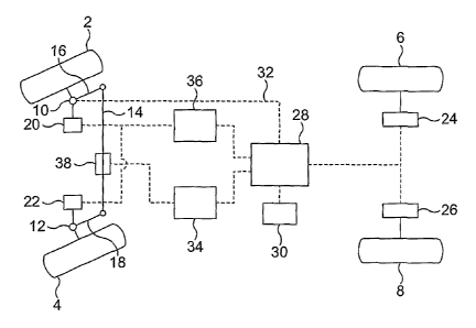
The vehicle shown in Figure 1 comprises front steered wheels 2, 4 and rear
wheels 6,
8. The steered wheels 2, 4 are mounted on the rest of the vehicle for steering
movement about kingpin, or steering, axes 10, 12. Steering motion of the two
wheels 2
and 4 is coordinated by a track rod 14 which interconnects steering arms 16,
18 of the
wheels 2, 4 in a conventional manner.
The wheels 2, 4 can be driven in rotation by electric motors 20, 22.
Guidance of the vehicle is performed under the control of a control means 28,
such as
a computer. The memory of the computer 28 stores a path which the vehicle is
to
follow, for example the path between an originating station and a destination
station of
the PRT system in which the vehicle operates. The computer also receives
signals
from position sensing means 30 which enable the computer 28 to establish the
current
actual position of the vehicle. The position-sensing means 30 may be part of
the
computer 28, but is shown separately for clarity.
CA 02650134 2008-10-22
WO 2007/125283 PCT/GB2007/001453
The computer 28 also receives a signal, along a line 32, representing the
steering
angles of the wheels 2, 4. In Figure 1, the line 32 is shown as extending only
from the
kingpin 10 of the wheel 2. This may be adequate, since the track rod 14
ensures that
5 there is a fixed relationship between the steering angles of the wheels 2
and 4, but
alternatively a separate signal representing the steering angle of the wheel 4
may be
input to the computer 28.
Outputs of the computer 28 are connected to a steering mechanism controller 34
and a
torque controller 36. The steering mechanism controller 34 supplies control
signals to
a steering motor 38, and the torque controller 36 supplies control signals to
the wheel
motors 20, 22.
In operation of the vehicle in a PRT system, a passenger entering the vehicle
at an
originating station is able to specify, for example by means of a touch
screen, the
desired destination station. Details of the journey are then input to the
computer 28,
which generates a desired path along the trackway of the network from the
start point
to the end point.
As the vehicle proceeds along the path, the position sensing means 30 monitors
the
position of the vehicle both along the path, and laterally of the path. For
example, the
lateral position of the vehicle may be established by means of distance
sensors
installed on the vehicle, and capable of monitoring the distances between the
sensors
and a reference surface, for example a kerb, at the side of the trackway.
Signals from
these sensors, and possibly from other position determining equipment, such as
a
Global Positioning System (GPS) receiver are supplied to the position
determining
means 30 which then determines the current position of the vehicle and
supplies a
signal representing this to the computer 28. The computer 28 compares the
current
position with the desired position and generates an output representing a
steering
angle of the wheels 2, 4, which, if adopted, will bring the vehicle back to
the
predetermined path. This signal is compared with a signal received by the
computer
28 along the line 32 representing the actual steering ang(es of the wheels 2,
4. If the
target steering angle differs from the actual steering angle, then a
correction signal is
supplied to the steering mechanism controller 34 and to the torque controller
36 to
cause them to generate control signals for the steering motor 38 and the
electric
motors 20 and 22 to cause the wheels 2, 4 to move to the target steering
angle.
CA 02650134 2008-10-22
WO 2007/125283 PCT/GB2007/001453
6
It will be appreciated that the steering motor 38 acts directly on the track
rod 14 to
cause it to turn the wheels about the kingpin axes 10, 12. The force applied
by the
steering motor 38 is represented by an arrow F in Figure 2. In normal
operation, this
motion is assisted by a difference in the torques applied by the motors 20, 22
to the
wheels 2, 4. Referring to Figure 2, which shows a conventional steering
geometry, it
will be noted that the projected kingpin axis 10, 12 intersects the ground 40
at a
position 42 which is offset from the nominal contact point 44 between the
wheel 2, 4
and the ground 40. Consequently, traction generated at the ground 40 along the
line of
action T by the respective drive motor 20, 22 will tend to cause the wheel 2,
4 to turn
about the kingpin axis 10, 12. If both wheels receive the same torque, the
turning
moments of the two wheels 2, 4 will balance each other out by way of the track
rod 14,
and no net turning effect will occur. However, if one of the drive motors, for
example
the drive motor 20, is controlled to deliver greater torque to the wheel 2
than the drive
motor 22 delivers to the wheel 4, then the turning moment applied to the wheel
2 will
tend to cause both wheels to turn to the left, as shown in Figure 1. In some
circumstances, torque in opposite senses may be applied to the wheeis 2, 4, in
other
words so that one of them is driven and the other is braked.
In normal operation, this turning effect achieved by the differential torque
applied by the
drive motors 20, 22 will supplement the steering movement caused by the
steering
motor 38. However, should the steering motor 38 or the steering mechanism
controller
34 fail, then steering will remain possible by appropriate control of the
drive motors 20,
22 by the torque controller 36. Of course, should either of the drive motors
20, 22 fail,
then drive will nevertheless be maintained through the other motor (20 or 22)
while
steering can be maintained by means of the steering motor 38.
Thus, the two steering systems of the vehicle can operate independently if
necessary
so that, in the event of failure of one of them, the other can enable the
vehicle to
proceed to the destination station. The vehicle can then be taken out of
service for
investigation and repair.
Furthermore, it will be appreciated that a speed difference between the driven
wheels
on opposite sides of the vehicle will have an effect on the travel direction
of the vehicle
even if the wheels are not steered. In a modification of the system,
therefore, the
torque controller 36 may be replaced by, or supplemented by, a speed
controller which
CA 02650134 2008-10-22
WO 2007/125283 PCT/GB2007/001453
7
receives signals from the computer 28 and controls the speed of each wheel 2,
4 to
assist the steering of the vehicle.
Figure 3 is a flow chart which represents the control process carried out in
the
computer 28.
From the signal generated by the position-sensing means 30, the actual
distance
travelled along the path is determined. From the parameters of the journey
itself, such
as the start time and the time elapsed, the computer 28 is able to calculate
the desired
or expected distance travelled. Signals representing the desired and actual
distances
travelled are input to a desired speed calculation block 50 which calculates a
desired
speed, taking account of pre-set maximum and minimum acceptable speeds and
acceleration levels. The output of the block 50 is passed to a subtractor
which
receives, as a second input, an actual speed signal from a speed sensor 54.
The
output of the subtractor 52 represents a speed error, and is input to a net
drive force
demand calculation block 56 which outputs drive force demand signals to
subtractors
58, 60 associated with the right and left wheels 2, 4 respectively.
Meanwhile, signals representing the desired and actual paths and the speed of
the
vehicle are input to a desired steering angle calculation block 62, which
calculates a
desired steering angle for the wheels 2, 4 which would cause the actual path
to
converge on the desired path. The output of the biock 62 is input to a
subtractor 64,
which also receives a signal (along the line 32) representing the actual
steering angle
of the wheels. The output of the subtractor 64 represents a steering angle
error, and
this is input to both a steering actuator force demand calculation block 68
and to a
differential drive force demand calculation block 70.
The steering actuator force demand calculation block 60 calculates a steering
actuator
force demand which is input to the steering mechanism controller 36 and
results in
appropriate operation of the steering motor 38.
The differential drive force demand calculation block 70 calculates the
difference in
drive force exerted by the wheels 2, 4 required to reduce the steering angle
error. The
output of the block 70 is supplied to the subtractors 58, 60, which generate
output
signals representing right-hand and left-hand drive force demand,
respectively. The
signals are input to the torque controller 36, which controls the motors 20,
22 to provide
CA 02650134 2008-10-22
WO 2007/125283 PCT/GB2007/001453
8
the required drive forces.