Note: Descriptions are shown in the official language in which they were submitted.
CA 02650172 2009-01-19
FLARED LEG PRECAST CONCRETE BRIDGE SYSTEM
CROSS REFERENCE TO RELATED APPLICATION
[0001.] Not applicable.
STATEMENT REGARDING FEDERALLY SPONSORED
RESEARCH OR DEVELOPMENT
[0002] Not applicable.
SEQUENCE LISTING, TABLE OR COMPUTER
PROGRAM ON COMPACT DISC
[0003] Not applicable.
FIELD OF INVENTION
[0004] This invention relates generally to precast concrete structures and
more
particularly to precast concrete bridge and culvert units.
BACKGROUND OF THE INVENTION
[0005] It is known in the art to use precast concrete building systems in the
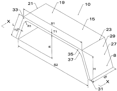
construction
of culverts and bridges. The structures built according to these systems are
composed of one or
more elemental sections successively placed adjacent to one another. In this
regard the
CA 02650172 2009-01-19
individual sections are placed side-by-side in the ground to form, for
example, a bridge beneath
traffic-ways for road-over-road or road-over-stream crossings. The elemental
sections can also
be used to construct culverts and underground storage vaults. By precasting
multiple sections
offsite for subsequent erection onsite, overall project construction time can
be compressed as
compared to cast-in-place concrete structures. Also, due to the improved
quality control
associated with facility manufacturing, the end-product structure provides
greater inherent
durability over that of a cast-in-place concrete structure. Bridges, culverts
and underground
storage structures can be made from the same elemental sections. Accordingly,
in this
application the word "bridge" or "bridge assembly" is defined to include a
culvert or
underground storage structure, unless otherwise indicated.
[0006] There are two basic varieties of prior art precast bridge systems:
flattop and
arched-top. FIGS. la and lb respectively depict the elemental sections of
these prior art
systems. As seen in FIGS. la and lb, both the flattop and arched-top section
comprise a
structural top member 2 integrally connected to and abridging two spaced-apart
legs 4. The
arched-top bridge section of FIG. lb is considered by many to be esthetically
more pleasing than
the flattop section of FIG. la. On the other hand, the existing flattop system
beneficially
maximizes waterway area for water flow of streams and creeks. Structurally,
however, the
arched-top bridge system is generally more efficient than the flattop systems.
The arched-topped
section has the ability to carry vertical loads through arching. This arching
creates significant
outward horizontal thrust in the legs that results in a structure highly
dependent on the support of
adjacent backfill. By comparison, the prior art flattop bridge sections have
higher bending
moments and no arching. The flattop section is less dependent on the support
of adjacent
backfill for structural integrity. However, both the prior art flattop and
arched-top bridge
systems derive a significant degree of their structural capacity from the
support provided by
2
CA 02650172 2009-01-19
backfill material and are thus susceptible to foundation movements and
shifting because of
poorly placed backfill. Also, in the case of the arched-top system, in order
to manufacture a
wide range of spans and rises, a manufacturer must have several different sets
of concrete forms
on hand. These forms are expensive to manufacture and difficult to use in a
production driven
environment.
SUMMARY OF THE INVENTION
[0007] The present invention is directed to a precast concrete system that
addresses the
disadvantages and deficits of the prior art flattop and arched-top bridge
systems. In this regard,
the present invention is directed to a precast concrete bridge system
comprising precast sections
that include a flat top slab integrally abridging two angled legs. As used in
this application the
words "angled," "angular" or "angularly" with reference to legs mean sloped or
inclined and not
substantially vertical or normal to the horizontal. The invention disclosed
herein provides the
desirable features of precast reinforced concrete structures but with lower
bending moments than
the prior art flattop bridge section and less horizontal thrust than the prior
art arched-top bridge
section. While achieving these advantages, the top slab of the present
invention bridge system
provides for a reduced horizontal effective span dimension as compared with
the prior art bridge
sections. Additionally, the combination of elemental section geometry with
properly placed and
compacted select backfill provides an efficient use of materials to carry
vertical loads across the
span.
[0008] The concrete building system of the present invention comprises a set
of parallel
spaced apart strip footers and one or more precast concrete sections supported
by the footers in
predetermined alignment. The footers may be established at identical or
differing elevations.
The horizontal distance between the leg bottoms defines a bottom-of-leg span.
Each precast
~
CA 02650172 2009-01-19
concrete section has a top slab integrally connected to a pair of flared legs,
which in the preferred
embodiment are equally flared. The top slab has a uniform thickness, an inner
surface, an upper
surface, a first end and a second end. The horizontal distance between the
first end and the
second end of the top slab defines an effective span. Each leg has a length, a
uniform thickness,
an inner surface, an outer surface, a top portion and a bottom portion. The
bottom portion of the
leg is supported by a footer. Critically, each leg depends from the top slab
at an effective flare
angle (as measured from the horizontal) to form a corner. Each precast
concrete section includes
a pair of haunch sections integrally formed between the top slab and the legs.
Specifically, each
haunch section extends from the inner surface of the top slab near its end to
the inner surface of
the top portion of the leg adjacent to that top slab end. The integral haunch
section results in a
localized corner thickness substantially greater than the uniform thickness of
the angled legs and
top member. The section has a rise defined by the vertical distance between
the bottom of the
lowermost leg and the inner surface of the top slab.
[0009] The effective span has a practical dimension length of between 60 and
90 percent
of the bottom-of-leg span and a preferred length of between 75 and 85 percent
of the bottom-of-
leg span. The effective flare angle of one or more of the depending legs can
vary between a
practical range of 55 to 85 degrees depending upon span. For short span
embodiments, the
elemental precast section can have an effective flare angle of practically
between 75 and 85
degrees, more preferably between 79 and 82 degrees and most preferably between
80 and 81
degrees. For long span embodiments, the elemental section can have an
effective flare angle of
practically between 55 and 80 degrees, more preferably between 65 and 75
degrees and most
preferably between 71 and 72 degrees. When utilizing these ranges, the
concrete building
system of the present invention can effectively accommodate structural rises
of between 6 and 14
feet and bottom-of-leg span distances between 12 and 48 feet, depending upon
effective flare
4
CA 02650172 2009-01-19
angle and the thickness of the legs and top slab. Additionally, each haunch
section can be
constructed to preferably include an arcuate inner surface having a radius. In
preferred
embodiment systems, the haunch radius varies between 24 to 36 inches depending
upon chosen
bottom-of-leg span. The present invention bridge system includes integral
reinforcing members
for added strength. As with conventional precast bridge systems, the present
invention system
can also be used as a culvert structure or underground storage vault. However,
unlike other
precast bridge systems the present invention bridge system can also be used as
a dam structure or
flow control device.
[0010] Effective flare angles, spans and rises can be individually adjusted to
accommodate a wide range of waterway cross sectional dimensions, flow paths
and volume-of-
flow requirements. The unique geometric shape of the system reduces the
resulting structure's
effective span at the top of the structure by sixty to ninety percent as
compared to prior art
systems. The angular legs reduce the bending moments developed in the
structure, but still
realize the contributory benefits from the lateral soil support provided by
the surrounding soil
without being highly dependent upon it.
[0011] The forming system for the elemental units of the present invention
bridge system
economizes the number of forms needed to produce the desired range of spans
and rises and
minimizes production set-up and stripping (form removal) time. The system also
accommodates
a wide range of panelized or modular retaining wall systems needed to contain
earthen fill above
and adjacent to the end sections and smoothly redirects stream flow through
the completed
systeni. Other features and advantages of the invention will be apparent from
the following
description and accompanying drawings.
CA 02650172 2009-01-19
BRIEF DESCRIPTION OF THE DRAWINGS
[0012] FIG. la is a front elevation view of the elemental section of the prior
art flattop
bridge system.
[0013] FIG. lb is a front elevation view of the elemental section of the prior
art arched-
top bridge system.
[0014] FIG. 2 is a phantom perspective view of a bridge assembly used in a
road-over-
stream application and comprising multiple precast sections of the present
invention.
[0015] FIG. 3 is an elevation view of the rear of the bridge assembly of FIG.
2 depicting
end section l0a witli adjoining head wall, sidewalls and wing walls.
[0016] FIG. 4 is a cross section view of a preferred embodiment section of the
present
invention system taken along line X-X of FIG. 5.
[0017] FIG. 5 is a perspective view of a preferred embodiment section of the
present
invention.
[0018] FIG. 6 is a phantom perspective view of an embodiment of the present
invention
system in a road-over-road application (tunnel) that can be used for vehicular
or pedestrian
traffic.
[0019] FIG. 7 is a cut-in-half cross section view of an alternative embodiment
section of
the pi-esent invention system with integral vertical leg extensions.
[0020] FIG. 8 is an elevation view of abridged preferred embodiment sections
of the
present invention placed end-to-end in a road-over-stream application or a
multi-celled
underground fluid storage tank.
[0021] FIG. 9 is a partial elevation view of a bridge unit of the present
invention
supported upon a pedestal wall.
6
CA 02650172 2009-01-19
[0022] FIG. 10 is a perspective view of a segment of the present invention
bridge system
adapted for use in a dam and land bridge application with a portion of the
surrounding water and
soil cut away.
[00231 FIG. 11 is a perspective view of a segment of the present invention
bridge system
adapted for use as a flow control structure including a precast spillway and
cast-in-place weir
with a portion of the surrounding water and soil cut away.
DESCRIPTION OF THE PREFERRED EMBODIMENTS
[0024] FIGS. 2, 6 illustrate a preferred embodiment bridge assembly 6
constructed by
way of the present invention system. FIGS. 3, 4 and 5 depict preferred
embodiment precast
sections used in the construction of bridge assembly 6. As shown by these
figures, bridge 6
comprises a series of precast elemental concrete sections 10 that are placed
in face-to-face
parallel alignment. The leg members 8 of each section sit atop two parallel,
continuous concrete
strip footers 12 that are formed in trenches and cast into the ground. As
shown in FIG. 4
concrete strip footer 12 is cast with recess 13 that is sized to receive
bottom portion 31 of leg 8.
After placement, leg 8 is locked in-place onto footer 12 with cementitious
grout. Depending
upon site characteristics or other requirements, strip footers 12 may be
connected by a cast-in-
place concrete slab (not shown).
[0025] As sllown in FIG. 4, legs 8 depend angularly from top slab 15 at an
effective flare
angle A as measured from the horizontal. In a preferred embodiment, the
effective flare angle A
of both legs 8 is equal. However, effective flare angle A can be varied as
between legs 8 to
accommodate site topograplly. Top slab 15 includes uniform thickness T1, an
inner surface 17
an upper (outer) surface 19, a first end 21 and a second end 23. The
horizontal distance between
first end 21 and second end 23 defines an effective span S1. Leg 8 has a
length L, a uniform
7
CA 02650172 2009-01-19
thickness T2, an imier surface 25, an outer surface 27, a top portion 29 and a
bottom portion 31.
Bottom portion 31 of the leg is supported by footer 12. The horizontal
distance between the
inner surfaces 25 of bottom portions 31 of legs 8 defines a bottom-of-leg span
S2.
[0026] Each leg depends angularly from an end 21, 23 of the top slab at an
effective flare
angle A (as measured from the horizontal) to forrn a corner 33. The elemental
precast concrete
section of the present invention includes a pair of haunch sections 35, each
integrally formed
between top slab 15 and legs 8 at comers 33. Specifically, each haunch section
35 extends from
inner surface 17 of top slab 15 near an end 21, 23 to inner surface 25 of top
portion 29 of the leg
8 nearest that top slab end. Integral haunch section 35 results in a corner
thickness greater than
the uniform thicknesses T1, T2 of the top slab and the angled leg to which it
is integrally formed.
The elemental section has a rise R defined by the vertical distance between
the elevation of
bottom portion 31 and the elevation of inner surface 17 of top slab 15.
[0027) As is best shown in FIG. 3, in a preferred embodiment end section I0a
is
manufactured with integrally attached headwall 14 to contain soil fill on top
of the bridge
assembly 6. Alternatively, head wall 14 may be independently cast and then
mechanically
connected to end section 10a. Precast concrete sidewall 16 may be integrally
cast onto angled
legs 8 or independently cast and then mechanically connected to angled leg 8.
Wingwall 18
extends upward from top of footer 12 to meet the elevation of the top of
headwall 14. Sidewalls
16 provide for a convenient connection to wingwalls 18, which can be either
precast or cast-in-
place concrete, and extend outwardly at various horizontal angles to define an
entrance and exit
for water flowing in the channel formed within the soil.
[0028] During installation of the disclosed bridge system, sections 10 abut
one another in
face-to-face alignment and are temporarily lield in-place by the strip footer
keyways and
blocking. Subsequent to grouting of the keyways, sections 10 are backfilled
and covered with
8
CA 02650172 2009-01-19
compacted soil. As installed, sections 10 can support a roadbed or roadway
pavement on top of
the assembled bridge system. The roadway can cross the bridge assembly at any
angle relative
to the longitudinal axis of the assembly.
[0029] Top slab 15 and angular legs 8 are flat and of respective uniform
thickness T1 and
T2, except at the haunches 35. In the embodiments discussed herein, the
thickness of angled
legs 8 and top slab 15 will range between eight inches and fourteen inches,
inclusive. Haunches
35 are thickened for strength and include inner surface 37. In the preferred
embodiment, inner
surface 37 is concavely arcuate in form such that inner surface 17 of top slab
15 smoothly curves
into connection with inner surface 25 of angled leg 8. Arcuately formed haunch
section 35 has a
radius Rl, which can vary practically between eight and forty-two inches
depending on the
length of bottom-of-leg span dimension S2.
[0030] As shown in FIG. 4, the overall height H of elemental section 10 is
equal to the
sum of rise R and top slab thickness T1. Rise dimension R can range from about
four feet to
fourteen feet. The effective span Sl will range between 60 and 90 percent of
the bottom-of-leg
span dimension S2. The preferred effective span range is between 75 and 85
percent of the
bottom-of-leg span. The width W of section 10 may range between about four
feet and ten feet,
depending upon the bottom-of-leg span, and is preferably between six to eight
feet for most
spans.
[0031] The concrete of precast section 10 is reinforced in the conventional
manner. Such
reinforcement may include a grid of crossing steel reinforcing rods, mesh or
members embedded
within angular legs 8 and flat top slab 15. Such reinforcing rods, mesh or
members are situated
relatively close to both outer surfaces 19, 27 and inner surfaces, 17, 25. The
reinforcing rods
form grids that significantly increase the load carrying strength of precast
section 10 enabling it
to handle heavy loads or traffic on pavement above. Legs 8 and top slab 15 may
include
9
CA 02650172 2009-01-19
embedded tendons in place of or in addition to the steel grids. These tendons
may be pre- or
post-tensioned. Legs 8 and top slab 15 may include in place of or in addition
to the above
reinforcement features, mixed-in steel fibers (fiber mesh) to enhance overall
durability and
capacity for extei-nal loading.
[0032] For practical application purposes, the embodiment sections of the
present
invention precast bi-idge system can be categorized into short span
embodiments and long span
embodiments. Elemental sections of the short span embodiment have a bottom-of-
leg span
dimension S2 that ranges from 12 feet to 22 feet and a rise dimension R that
ranges from 6 feet
to 14 feet. The elemental section of short span embodiment can have an
effective flare angle of
practically between 75 and 85 degrees, more preferably between 79 and 82
degrees and most
preferably between 80 and 81 degrees. The elemental section of the short span
embodiment can
have a haunch radius of practically between 8 and 42 inches, more preferably
between 18 and 33
inches and most preferably between 23 and 25 inches. The haunch radius of the
preferred short
span embodiment is 24 inches.
[0033] The short span embodiment section can be further sub-divided for
general
application purposes into two groups, each with a different leg and flat top
thickness. For
embodiment sections with a bottom-of-leg span dimension of 12 feet to 18 feet,
the uniform
thickness of the legs and top slab may be as thin as 8 inches. Thus, one short
span series
embodiment could have the following dimensions: a uniform thickness of the top
slab of no
greater than 8 inches, a uniform thickness of each leg of no greater than 8
inches, a bottom-of-leg
span of at least 12 feet and a rise of at least 6 feet. For units with bottom-
of-leg span dimensions
of 18 to 22 feet, the uniform thickness of the legs and top slab is preferably
10 inches, but may
also be as little as 8 iiiclles. The effective span to bottom-of-leg span
ratio for the short span
series can vary between 0.6 to 0.9, with the preferred ratio being between
0.75 to 0.85.
CA 02650172 2009-01-19
[0034] Elemental sections of the long span embodiment have a bottom-of-leg
span
dimension S2 that ranges from 22 feet to 48 feet and a rise dimension R that
ranges from 6 feet
to 14 feet. The elemental section of long span embodiment can have an
effective flare angle of
practically between 55 and 80 degrees, more preferably between 65 and 75
degrees and most
preferably between 71 and 72 degrees. The elemental section of the long span
embodiment can
have a haunch radius of pi-actically between 10 and 42 inches, more preferably
between 24 and
42 inches and most preferably between 35 and 37 inches. The haunch radius of
the preferred
long span enlbodiment is 36 inches. The long span embodiment section can be
further sub-
divided for general application purposes into two groups, each with a
different leg and flat top
thickness. For embodiment sections with a bottom-of-leg span dimension of 22
feet to 40 feet,
the uniform thickness of the legs and top slab may be as thin as 12 inches.
Hence, one long span
series embodiment could have the following dimensions: a uniform thickness of
the top slab of
no greater than 12 inches, a uniform thickness of each leg of no greater than
12 inches, a bottom-
of-leg span of at least 22 feet and a rise of at least 6 feet. For units with
bottom-of-leg span
dimensions of 40 to 48 feet, the thickness of the legs and top slab may be as
thin as 14 inches.
Hence, another long span series embodiment could have the following
dimensions: a uniform
thickness of the top slab of no greater than 14 inches, a uniform thickness of
each leg of no
greater than 14 inches, a bottom-of-leg span of at least 40 feet and a rise of
at least 6 feet. The
effective span to bottom-of-leg span ratio for the long span series can vary
between 0.6 to 0.9,
with a preferred ratio between 0.75 and 0.85.
[0035] The flared leg precast bridge system of the present invention provides
advantages
over the prior art flattop and arched-top systems. Specifically, the above
described values and
relationships between effective flare angle and effective span dimension
provide an optimum
configuration for reducing bending moment and horizontal thrust effects that
result from earth or
11
CA 02650172 2009-01-19
ground (i.e., dead) loads as well as vehicular traffic (i.e., live) loads on
the top slab. As
compared to prior art systems, the top slab of the present invention system
has a reduced
effective span dimension. Additionally, all continuous buried structures
benefit from soil-
structure interaction (SSI). The geometry of the precast elemental sections of
the present
invention make effective use of the SSI that takes place between the structure
and the
surrounding soil mass. SSI utilizes the lateral or horizontal forces acting
against the legs to aid
in supporting the earth or ground and other loads on the top slab. In
addition, the angular legs
provide a convenient means to connect the sidewalls and vertical wingwalls in
such a way as to
produce a sinooth flow of water into and out of the bridge system formed by
multiple sections
placed face-to-face.
[0036] Production of the system sections can be efficiently completed using
metal forms
situated on-end (i.e., forms are filled vertically in the direction of section
width W). This type of
form design allows for a convenient means to vary leg angle, rise and span.
The section span
lengths and rise heights can be conveniently varied by adding or removing
straight form
segments along the top slab or angled legs. Additional changes in section span
and rise length
can also be conveniently made by simply repositioning bulkheads located at the
bottom-of-leg
portion of the form. As shown in FIG. 7, section rise R can be increased by
adding inwardly-
angled (vertical) extensions of height H1 to the bottom portion 31 of legs 8.
In this embodiment,
legs 8 of precast section 10 include integral depending leg extensions 44. By
including leg
extensions on the elemental sections, the sections can be easily tailored to
meet the needs of
nearly any site-specific application.
[0037] Referring to FIG. 8, two precast sections 10 are arranged in an end-to-
end
configuration on corresponding continuous concrete strip footers 12. The
angular or filleted
space 40 between the adjoining angled legs of the sections is closed on top by
a separate precast
12
CA 02650172 2009-01-19
concrete panel 42, which panel may be partially reinforced with mild steel
reinforcement, pre-
stressing strand pre-tensioned before the casting process or a combination of
both. Panel 42 is
set into recesses or benches 46 that are formed into the top portions 29 of
legs S. This
embodiment assembly of the precast sections and flat panels is ideally suited
for forming a multi-
spanned stream crossing. In this application, the filleted space can be
expanded with a wider
central strip footer and longer spanned precast or prestressed panels to gain
increased waterway
area without the addition of an additional line of precast sections. Further,
one line of precast
sections can be nlanufactured with a shorter rise than the other line to
provide for a main channel
and a separate, higher elevation overflow channel.
[0038] As with other prior art systems, the precast sections of the present
invention
system are ideally suited for construction of underground storage or retention
tanks. Similarly,
the precast sections of the present invention system may be manufactured with
one leg width W
of the section narrower than the opposite leg width, thus creating a wedge-
shaped (tapered)
section to produce a curved assembly.
[0039] Referring to FIG. 9, certain applications may require a rise or height
that is
beyond normal precast shipping restrictions, or the cost of the additional
right-of-way for a wider
multi-spanned al-rangement is cost prohibitive. In these cases, the precast
sections of the present
invention system can be installed on cast-in-place concrete pedestal walls
that add vertical height
and associated waterway ai-ea to the cross section without adding an
additional line of precast
sections to the assembly. FIG. 9 is a partial elevation view of a bridge unit
of the present
invention supported upon pedestal wall 72 in a situation requiring the overall
rise to be greater
than what can be practically shipped. Pedestal wall 72 is integrally formed to
concrete strip
footers 12 or an appropriately sloped and reinforced concrete base slab 73
that supports both the
pedestals and the precast section.
13
CA 02650172 2009-01-19
[0040] The flared leg elemental sections of the present invention also can be
installed to
impound water as a dam or flow control structure. The use of the elemental
sections in these
applications is shown in FIGS. 10 and 11. FIG. 10 depicts a dam assembly 106
of precast flared
leg sections. As shown in these diagrams, cast-in-place concrete strip footers
112 are cast in
trenches in the ground and the flared leg sections 108 of the present
invention are installed on top
of the footers. One or niore layers of fill (not shown) are placed underneath
the top slabs 115 of
sections 110 before or after the sections are installed. The fill is placed
within the one or more
precast concrete sections to roughly approximate the inner surfaces of the
flared legs and the top
slab. The sections are then sealed. To achieve barrier integrity, the interior
portions of the
sections 110 can be filled with impermeable compacted fill, lean concrete,
flowable fill or many
other materials. The completed assembly can also include steel, vinyl or
concrete sheet pile
installed prior to installation of the elemental sections as a water cut-off.
The dam assembly of
sections can be provided with through-dam components for flow metering or
emergency draw-
down. Additionally, the dam assembly can include access ports to allow entry
into the interior
portion of the assembled sections for maintenance and inspection access to
intemal equipment.
[0041] FIG. 11 depicts an assembly 206 of precast flared leg sections forming
a concrete
spillway in conjunction with a cast-in-place or precast concrete weir. Flared
leg sections 210 are
installed on footers 212 as described above, but with one or more sections
210a having a shorter
rise to create the spillway portion. Sections adjacent to these shorter rise
sections have integrally
attached closure walls 250 to meet up with the underside of the adjacent full-
sized section and
the weir would be placed on top of the spillway.
[0042] Dam or flow control structures comprising flared-leg precast sections
can also be
used as land bridges. The sections for this application would be manufactured
with female
keyways in both faces of each section that would be grouted in-place after
installation. The
14
CA 02650172 2009-01-19
grouted keyways seal the spaces between the units against impounded water
infiltration and
provide a positive means of shear force transfer between units due to
pedestrian and/or vehicular
traffic on the top slab. As an added measure of security against water
infiltration and for shear
transfer between sections, the sections can be manufactured with ducts through
which post-
tensioning strands can be installed and tensioned after section installation.
[0043] While the flared-leg precast concrete bridge and dam systems herein
described
constitute preferred embodiments of the invention, it is to be understood that
the invention is not
limited to these precise embodiments, and that changes may be made therein
without departing
from the scope and spirit of the invention as defined in these claims. Those
of ordinary skill in
the art will appreciate that the invention can be carried out with various
other minor
modifications from that disclosed herein, and same is deemed to be within the
scope of this
invention.