Note: Descriptions are shown in the official language in which they were submitted.
CA 02650209 2008-10-21
WO 2007/127782
PCT/US2007/067388
METHOD AND APPARATUS FOR ADAPTIVELY CONTROLLING SIGNALS
FIELD OF INVENTION
This invention relates generally to signal transmission systems, including
those associated with cellular infrastructure, where signal peaks may be
advantageously reduced, and more particularly to a method and apparatus for
reduction of peak power requirements by adaptively controlling signals.
BACKGROUND OF THE INVENTION
Wireless communication basestations, networks, and other systems use power
amplifiers to transmit signals to cellular phones, handheld messaging devices,
computers, personal electronic assistants, and other devices. A power
amplifier
increases the average power of the transmitted wireless signal sufficiently to
maintain
a reliable communication link at any required distance. This is necessary
because
signal waveforms are used to efficiently convey information between a
transmitter
and a distant receiver. Since noise and interference are combined with the
signal
waveform at the receiver, the transmitter must amplify its waveform prior to
transmission sufficiently to guarantee that the ratio of received signal
energy to
noise/interference energy exceeds a specified value; otherwise the receiver's
additive
noise/interference can overwhelm the signal energy, resulting in loss of
infounation
over the data link. This constraint applies to communication systems employing
wireless transmission, including radio frequency (RF), optical and audio
technologies.
Pre-transmission amplification of the information-bearing signal waveform
constitutes one of the major costs associated with modern information
transfer. Figure
1 depicts a typical relationship between amplification cost and the maximum
(peak)
magnitude of the signal waveform. Package cost generally dominates for low
peak-
power amplifiers. However, beyond some point, additional peak-power capability
CA 02650209 2008-10-21
WO 2007/127782
PCT/US2007/067388
results in exponentially-increasing amplifier costs. For this reason, signal
processing
techniques capable of reducing peak values of the transmitted waveform are
greatly
valued in modem wireless signal transmission systems.
The transmitted signal's power varies depending on both the modulation type
and the data sequence being transmitted, which results in peaks and troughs in
the
instantaneous power as a function of time. The complexity and cost of an
amplifier is
highly dependent on the maximum instantaneous power it must accommodate.
Consequently, basestation providers and operators and other electronics users
seek
ways to lower the instantaneous or "peak" power requirements of the relevant
system.
To reduce system peak power requirements, a provider may simply limit the
maximum amplifier output power by constraining or "clipping" the maximum
magnitude of the amplifier's output signal. Clipping the amplifier output
effectively
reduces the peak power output requirement while still providing ordinary
amplification for non-peak signals. Since the cost of a power amplifier
rapidly
increases as it is required to accommodate higher peak power levels, clipping
can
significantly reduce system cost. Clipping may be particularly attractive in
applications in which large peaks occur only occasionally. For example, a
single
amplifier often simultaneously amplifies signals for multiple channels.
Occasionally,
the multiple channel signals constructively combine to generate a relatively
high peak.
The amplifier must either fully amplify the peak, requiring an expensive high
peak-
power amplifier, or the output magnitude may be clipped to facilitate the use
of a
lower peak-power, less expensive amplifier.
In wireless comminications and networking, however, clipping is
unacceptable. Clipping induces spectral regrowth, creating spectral energy in
potentially restricted spectral regions. The electromagnetic spectrum is a
finite
2
CA 02650209 2008-10-21
WO 2007/127782
PCT/US2007/067388
resource, and it is strictly apportioned by restrictions from various
governmental
regulating agencies to minimize interference from competing users. The various
spectrum users receive permission to transmit within certain bandwidths and
are
ordinarily prohibited from transmitting outside of the designated bandwidth.
Even
within the so-called "unlicensed bands", strict FCC standards regulate
spectral
emissions to minimize interferences. Because spectral regrowth adds
unacceptable
frequency components to the signal, spectrum regulations do not permit
clipping as a
solution for high-power amplifier requirements.
The relationship between signal peaks and amplifier characteristics is of
great
significance with respect to wireless communications. Efficient power
amplifiers
exhibit an intrinsically nonlinear relationship between input and output
power. The
relationship between amplifier input and output power is depicted in the lower
curve
240 of Figure 2. For low levels of input power, the amplifier output signal is
essentially a linearly-amplified replica of the input. However, at higher
input signal
power levels, the amplifier output reaches an upper limit, the amplifier
saturation
power, which cannot be exceeded. The region of the amplifier curve near the
saturation point is nonlinear. Operation of the amplifier near its nonlinear
amplification region generates unacceptable nonlinear noise which violates
regulatory
spectral masks, forcing operation at a lower input power level. Prior art
includes
numerous techniques which can be used to 'linearize' an amplifier, thus
mitigating the
nonlinear characteristic, and approaching the ideal linear relationship shown
in the
upper curve 242 in Figure 2.
Amplifier nonlinearities convert input signal energy into nonlinear spectral
energy which may violate regulatory spectral mask constraints. It is therefore
necessary to limit the strength of the signal input to the amplifier so that
its magnitude
3
CA 02650209 2008-10-21
WO 2007/127782
PCT/US2007/067388
only rarely extends beyond the linear region of operation. As Figure 2 shows,
the
value of amplifier linearization is that it can greatly extend the upper
limits of the
amplifier's linear region. After the amplifier has been linearized to the
practical limit,
generation of unwanted nonlinear spectral components may be further reduced by
limiting the likelihood that the signal magnitude extends beyond the
amplifier's linear
region. This reflects the important fact that generation of unwanted nonlinear
components requires that signal peaks extend beyond the amplifier's linear
region;
both signal and amplifier characteristics are involved, and both must be
addressed.
The need for peak-reduction processing was greatly increased by the relatively
recent widespread adoption of so-called 'multi-channel' signal waveforms for
wireless infrastructure systems. The adoption of multi-channel signaling (MCS)
occurred because of the strong economic incentive to combine several
independent
signal waveforms wherein all of the signals are transmitted in the same
spatial
direction and all signals can then share a single antenna. Previously,
infrastructure
basestations separately amplified each waveform, which were then combined
using a
`diplexer' before sending the composite amplified signal to the antenna.
However,
since a four-signal high-power diplexer can cost on the order of $10,000, an
alternative solution in the form of MCS was developed. In MCS, several
independent
signal waveforms are generated and combined while still in digital form. The
combined signals then share a common frequency translation to RF, a common
amplifier and a common antenna. The heavy, bulky, and expensive diplexer is
eliminated. The digital channel waveforms remain separated by the inter-
channel
frequency spacing, typically less than ten megahertz, so that inexpensive
(relatively
low rate) digital processing can easily generate the composite waveform.
Figure 3
depicts the baseband complex spectra associated with four adjacent cellular
signals.
4
CA 02650209 2008-10-21
WO 2007/127782
PCT/US2007/067388
Note that the frequency offsets correspond only to the relative transmission
frequencies, since the common RF frequency translation will be added to the
MCS
waveform after it has been converted into analog form. While MCS provides an
economically advantageous solution to the diplexer problem associated with
earlier
transmission systems, MCS greatly aggravates the peak magnitude problem, since
the
signal peak of an MCS waveform is much higher than that of each of its
component
signal waveforms. Thus, MCS remains an incomplete solution to the diplexer
problem
of earlier transmission systems until peak reduction in MCS is effectively
addressed.
In addition to the emergence of MCS waveforms with their large peak
magnitudes, several important worldwide wireless standards [e.g. 802.11 (WiFi)
and
802.16 (WiMAX)] have adopted orthogonal frequency-division multiplexing
(OFDM) waveforms which use parallel transmission of many narrowband
components. An OFDM signal may be considered as a special case of multi-
channel
transmission, with no spectral spacing between adjacent channels, and short
burst
(rather than continuous) transmission. The WiMAX waveform, which has been
proposed as a potential worldwide solution for all wireless communication,
uses
basestation transmissions consisting of OFDM with several hundred channels.
These
channels are allocated to many users, with modulation types and power levels
of those
sets of channels sent to each user selected based on the path attenuation for
each
distinct physical link. The large peak power level variation of the many OFDM
channels generates peak-reduction demands similar to those of MCS. OFDM must
also satisfy stringent error vector magnitude (EVM) constraints for each set
of
channels allocated for each individual user, in the face of dynamically-
varying
channel modulation orders, path losses, and signal power levels. Peak-
reduction
processing therefore offers economic advantages to modem wireless
communication
CA 02650209 2008-10-21
WO 2007/127782
PCT/US2007/067388
systems, both RF and optical, both MCS and OFDM, as well as any other system
in
which signal peaks are beneficially reduced based on any standard, requirement
or
economic factor including, for example, digital radio and television broadcast
systems.
Numerous technical papers directed to techniques for peak-reduction
processing have been published, and several patents have been awarded, as
would be
expected for such an economically vital challenge.
One peak-reduction processing approach simply modifies the information
stream itself prior to the signal generation (modulation) operation. See,
e.g., R. W.
Bauml, R. F. H. Fisher, and J. B. Huber, "Reducing the Peak-to-Average Power
Ratio
of Multi-Carrier Modulation by Selected Mapping," Electron. Lett., vol. 32,
no. 22,
Oct. 1996, pp. 2056-2057; R. van Nee and A. de Wild, "Reducing the Peak-to-
Average Power Ratio of OFDM," Proc. IEEE VTC '98, May 1998, pp. 2072-2076.
While this technique reduces the peaks, it also significantly degrades the
performance
of error-correction coding, and has thus failed to fmd any significant market
acceptance.
Other approaches generate/modulate the information stream onto the
waveform, then alter that waveform to reduce its peak magnitude. See, e.g., T.
May
and H. Rohling, "Reducing the Peak-To-Average Power Ratio in OFDM Radio
Transmission Systems," Proc. IEEE VTC '98, May 1998, pp. 2474-78. One such
approach applies localized smoothly-varying attenuation to the signal in the
vicinity
of each peak. Yet another approach avoids generating nonlinear noise by simply
subtracting suitably scaled band-limited pulses from the signal to cancel each
peak.
While these approaches offer improvement, and at least two patents (U.S. Pat.
Nos.
6,366,319 and 6,104,761) have been granted for such an approach, they both add
6
CA 02650209 2008-10-21
WO 2007/127782
PCT/US2007/067388
excessive noise to the signal. These approaches also do not offer a
comprehensive and
systematic peak-reduction processing solution when the MCS channels are
dynamically varying in relative power levels and when the E'VM requirements of
each
channel also dynamically vary, as is the case with real-world MCS
transmission.
Still another technique is the classic clip-and-filter approach, which simply
passes the waveform through a "clipper" (i.e. hard-limiter), then filters the
clipped to
ensure compliance with regulatory spectral constraints. This approach is very
commonly used for peak-reduction of OFDM signals. e.g., R. O'Neill and L.
Lopes,
"Envelope Variations and Spectral Splatter in Clipped Multi-carrier Signals,"
Proceedings of the PMRC '95, September 1995, pp. 71-75; J. Armstrong, "New
OFDM Peak-to-Average Power Reduction Scheme," IEEE VTC 2001, May 2001,
Rhodes, Greece; J. Armstrong, "Peak-to-Average Power Reduction in Digital
Television Transmitters," DICTA2002 Conference, Melbourne, January 2002, pp.
19-
24; J. Armstrong, "Peak-to-Average Power Reduction for OFDM by Repeated
Clipping and Frequency Domain Filtering," Electronics Letters. vol. 38, No. 5,
February 2002, pp. 246-47; U.S. Patent Publication Nos. 2004/0266372,
2004/0266369; H.A. Suraweera, K. Panta, M. Feramez and J. Armstrong, "OFDM
Peak-to-Average Power Reduction Scheme With Spectral Masking," Int'l Symposium
on Comm. Systems Networks and Digital Processing (2004). The prior art in this
area
does nothing more than filter away out-of-band (00B) energy. However, hard-
limiting in this manner introduces passband nonlinear interference which
cannot be
removed by out-of-band filtering, and even out-of-band DFT filtering distorts
the
signal.
A conceptually-related peak reduction technique involves determining the
'excursion' (the portion of the signal exceeding a defined magnitude
threshold), then
7
CA 02650209 2008-10-21
WO 2007/127782
PCT/US2007/067388
filtering, scaling and time-aligning the excursion prior to subtracting it
from a suitably
delayed version of the original signal. This 'filtered excursion' approach
eliminates
signal distortion by applying filtering only to the excursion. The advantage
is that
spectral constraints are met without generating signal distortion, and peaks
can be
reduced by the maximum amount permitted by spectral constraints. The only
prior art
description of the filtered excursion approach, J. Armstrong, "PCC-OFDM with
Reduced Peak-to-Average Power Ratio," in IEEE 3Gwireless 2001, May 30-June 2,
2001, San Francisco, pp. 386-391, is limited to a non-standard variant of OFDM
that
involves overlapped symbols. The author has notably described clip-and-filter
as the
preferred peak-reduction approach for standard OFDM signals in all subsequent
publications.
This 'filtered excursion' approach forms the theoretical basis for the present
invention as described and claimed below, but the present invention goes
beyond
prior approaches in several significant respects. The prior art relating to
the filtered
excursion approach to peak-reduction processing properly recognized the need
for
interpolation prior to forming the excursion signal, although claiming,
incorrectly,
that over-sampling by a factor of only two was required. An increased sampling
rate
prevents nonlinear spectral components associated with the excursion from
aliasing
= back into the spectrum occupied by the original signal. This is important
because once
such nonlinear components occur, they cannot be removed by filtering. However,
the
prior art failed to recognize several critical factors involved in achieving
optimal peak
reduction. For example, the prior art did not recognize the need to vary the
attenuation-versus-frequency characteristic of the excursion filtering across
the signal
passband in order to properly protect the weaker signal components. The prior
art
described only static frequency-dependent attenuation of the out-of-band
excursion
8
CA 02650209 2008-10-21
WO 2007/127782
PCT/US2007/067388
spectral components, and pointedly instructed to "distort the in-band (i.e.
passband)
component of the difference (excursion) as little as possible." However, the
nonlinearity represented by excursion formation generates relatively uniform
spectral
nonlinearity noise across the signal bandwidth. Ensuring that all portions of
the signal
satisfy a minimal signal-to-noise ratio (SNR) constraint thus requires that
extra
attenuation be applied to the excursion in those spectral regions of weaker
signal
spectral energy. Even more critically, since the relative spectral energy of
different
signals varies dynamically, any such signal-responsive filtering must be
dynamically
adapted over time. Finally, each portion of a multi-channel signal must
independently
satisfy the error vector magnitude (EVM) constraint, which limits each
distinct
channel's SNR to one of a set of defined values, depending on that channel's
modulation type. The cited prior art failed to recognize the need to
dynamically adapt
the signal passband 'filtering' in order to satisfy this critical
specification. Finally, the
prior art failed to grasp the critical importance of applying dynamic scaling
to
different portions of the excursion prior to filtering in order to achieve
significantly
enhanced peak-reduction. An object of the present invention is thus to provide
gain
and other control strategies for optimizing peak reduction subject to noise
level (for
example EVM) constraints, signal dynamics and residual linear and nonlinear
distortion energy considerations.
SUMMARY OF THE INVENTION
A signal processing system for use in, for example, a communication and/or
amplifier system, according to various aspects of the present invention
includes an
excursion signal generator and a filter system. The excursion signal generator
identifies a peak portion of a signal exceeding a threshold, such as a
magnitude
threshold. Distinct portions of the excursion waveform are dynamically scaled
to
9
CA 02650209 2008-10-21
WO 2007/127782
PCT/US2007/067388
enhance peak reduction. The filter system filters a corresponding excursion
signal
having a magnitude and waveform corresponding to the portion exceeding the
threshold to remove unwanted frequency components from a scaled version of the
excursion signal. The filtered excursion signal may then be subtracted from a
delayed
version of the original signal to reduce the peak. In one embodiment, the
signal
processing system adapts to varying channel power levels by adjusting the
magnitude
threshold. The signal processing system may also adjust the scale of the
excursion
signal and/or individual channel signals, such as to meet constraints on
channel noise
and output spectrum, or to optimize peak reduction. In other embodiments, the
magnitude threshold, excursion signal and/or individual channel signals may
also be
adaptively adjusted based on, for example, a channel signal quality such as a
noise
level specification.
BRIEF DESCRIPTION OF THE DRAWING FIGURES
A more complete understanding of the present invention may be derived by
referring to the detailed description when considered in connection with the
following
illustrative figures. In the following figures, like reference numbers refer
to similar
elements and steps.
Figure 1 illustrates the relationship between the magnitude of the signal peak
and amplifier cost;
Figure 2 is a comparison of nonlinear and linearized amplifier
characteristics;
Figure 3 shows the baseband complex spectra associated with adjacent cellular
signals;
Figure 4 is an illustration of a complex signal over time and a magnitude
threshold;
CA 02650209 2008-10-21
WO 2007/127782
PCT/US2007/067388
Figure 5 shows an exemplary signal magnitude probability density function
(pdf);
Figure 6 shows an exemplary peak-reduced signal magnitude probability
density function;
Figure 7 depicts complementary cumulative distribution function (CCDF)
curves corresponding to four wideband code-division multiple access (WCDMA)
channels using various values for the magnitude threshold;
Figure 8 shows an optimized relationship between peak-reduction and
amplifier linearization;
Figure 9 shows exemplary raw excursion and filtered excursion waveforms
including a portion of a signal exceeding a defined threshold;
Figure 10 is a diagram of an excursion comprising multiple peaks or "peak
events";
Figure 11 is a block diagram of a communications system according to various
aspects of the present invention;
Figure 12 is a block diagram of a signal processing system having a peak-
power reduction component according to various aspects of the present
invention;
Figure 13 is a block diagram of an MCS modulator;
Figure 14 is a block diagram of a peak-power reduction component;
Figure 15 is a block diagram of an alternative embodiment of an excursion
signal generator;
Figure 16 is a block diagram of an embodiment of an excursion signal
generator;
Figure 17 is a block diagram of an excursion signal generator having multiple
scaling circuits;
11
CA 02650209 2008-10-21
WO 2007/127782
PCT/US2007/067388
Figures 18 A-C are frequency diagrams for a signal processed by a filter
system;
Figure 19 is a diagram of a channel filter for filtering subchannels;
Figure 20 is a magnitude diagram of a signal comprising multiple channels
having subchannels;
Figure 21 is a schematic of a detailed peak-reduction processing algorithm and
architecture including an exemplary channel scaling circuit;
Figure 22 illustrates a peak-reduction processing architecture;
Figure 23 is a schematic of a detailed peak-reduction processing algorithm and
architecture including an exemplary channel scaling circuit and circuitry for
adaptively varying the signal magnitude threshold;
Figure 24 shows a functional architecture for a typical excursion filter
system
514;
Figure 25 is a schematic representation of an excursion filter, a
corresponding
scaling filter, and their respective impulse responses;
Figure 26 is a plot describing the desired variation in the gain within each
channel filter 518 as a function of the filtered excursion power from each
excursion
filter channel;
Figure 27 is an illustrative plot showing gain-controlled EVM dynamics
corresponding to the algorithm and architecture of Figure 21;
Figure 27A is an illustrative plot showing the negligible spectral impact of
EVM-controlled gain using the algorithm and architecture of Figure 21;
Figure 27B shows a raw and peak-reduced CCDF plot for a combination of
four strong channels corresponding to the algorithm and architecture of Figure
23;
12
CA 02650209 2008-10-21
WO 2007/127782
PCT/US2007/067388
Figure 27C shows a plot of channel gains and EVM values versus time
corresponding to the CCDF plot of Figure 27B;
Figure 27D shows a raw and peak-reduced CCDF plot for one weak channel
and three strong channels corresponding to the algorithm and architecture of
Figure
23;
Figure 27E shows a plot of channel gains and EVM values versus time
corresponding to the CCDF plot of Figure 27D;
Figure 27F shows an improved CCDF plot achieved using cascaded peak
reduction;
Figure 28 is a block diagram of a scaling system having an
approximation/scaling filter;
Figure 29 is a TDMA waveform diagram of a sequence of time slots and a
time slot windowing signal;
Figure 30 is a block diagram of a filter system having additional filters and
a
switching system;
Figure 31 shows the magnitude of a TDMA signal comprising multiple
channels transmitted in a series of time slots;
Figure 32 is a block diagram of an OFDM peak-power reduction component
having an interpolator, a decimator, fast Fourier transforms (FFTs), and peak-
event
scaling, that shows mask generation based on channel-specific signal power and
EVM
constraints; and
Figure 33 is a block diagram of an OFDM peak-power reduction component
having an interpolator, a decimator, fast Fourier transforms (FFTs), peak-
event
scaling, mask generation based on channel-specific signal power and EVM
constraints, and adaptive control of the magnitude threshold.
13
CA 02650209 2008-10-21
WO 2007/127782
PCT/US2007/067388
Elements and steps in the figures are illustrated for simplicity and clarity
and
have not necessarily been rendered according to any particular sequence. For
example, steps that may be performed concurrently or in different order are
illustrated
in the figures to help to improve understanding of embodiments of the present
invention.
DETAILED DESCRIPTION OF EXEMPLARY EMBODIMENTS
The peak-reduction concepts of the present invention as discussed below are
presented primarily in the context of MCS (typically four WCDMA channels),
since it
simplifies the discussion to treat a smaller number of signal channels.
However, the
peak-reduction processing concepts of the present invention are equally
applicable to
OFDM signals. Similarly, the discussion below is presented in the context of
wireless
communications systems. However, the peak-reduction processing concepts of the
present invention are equally applicable to, for example, digital radio and
television
broadcast systems, including wired, terrestrial and satellite broadcast
systems. The
invention may, for example, provide benefits in the processing of any signal
conveyed
via variations in electromagnetic or acoustic fields. The inventive concepts
may
therefore be applied in optical data transmission and audio systems. The
present
invention thus includes within its scope the processing of signals, or
apparatus
therefor, in any system in which signal peaks may be advantageously reduced
based
on or pursuant to any standard, requirement or economic factor.
In the following discussion of the peak-reduction concepts of the present
invention, the signal is assumed to be represented by a sequence of complex
(i.e.
quadrature) samples that uniquely describe the signal's instantaneous
magnitude and
phase as these values dynamically evolve over time. The random information
borne
by the signal results in random dynamic variations in signal phase and
magnitude.
14
CA 02650209 2008-10-21
WO 2007/127782
PCT/US2007/067388
Figure 4 depicts such a signal as a time-varying trajectory. The cylindrical
surface
feature in Figure 4 simply corresponds to a defined constraint on signal
magnitude
(the `threshold'). Occasionally, the magnitude exceeds the threshold; in
Figure 4 the
extra-cylinder portion 410 of the signal 222 is illustrative of the portion of
the signal
which exceeds the threshold 412.
With reference to Figure 4, the 'clipped signal' is that portion of the signal
lying entirely within, or on, the cylinder, with the portion exterior to the
cylinder
replaced by its projection 410A onto the cylinder. The clipped signal
magnitude is
bounded by the threshold value; its phase is always identical to the original
(unclipped) signal. This constraint on signal magnitude can be expressed
mathematically as follows:
S(n) V , _ An)I M
C (n) ------- S(n)
V õ _ >M
An)
Where C(n) is the clipped signal, S(n) is the unclipped signal, IIS(n)11 is
the magnitude
of the unclipped signal, M is the magnitude threshold and Võ An) means "for
all
values of n such that the magnitude of S(n)." Each signal segment 410 outside
the
cylindrical surface is defined as an excursion event X(n):
X(n) S(n)¨ C(n)
Variation in signal magnitude can be quantified statistically. Figure 5 is a
schematic representation of the so-called magnitude probability density
function (pdf)
for a typical signal. Note that the magnitude pdf 250 exhibits a very long
tail (along
the Signal Magnitude axis), implying that very large values of signal
magnitude can
occur, albeit with declining likelihood as the signal magnitude gets larger.
The
purpose of peak-reduction processing is to alter the signal in a manner which
CA 02650209 2008-10-21
WO 2007/127782
PCT/US2007/067388
eliminates or substantially reduces the probability that the signal magnitude
will
exceed some defined (threshold) value. To totally eliminate the possibility
that the
signal magnitude will exceed such a threshold value would have the effect of
modifying the magnitude pdf from that depicted in Figure 5 to that depicted in
Figure
6. The vertical dashed line 412 of Figure 5 represents the magnitude threshold
value.
The increase in probability near the magnitude threshold in Figure 6 as
compared to
Figure 5 is a result of the fact that the area under the pdf curve must equal
unity. The
impact of a peak-reduction algorithm must therefore be able to transfer the
tail (above
the magnitude threshold) back into the body of the pdf (below the magnitude
threshold). MCS magnitude pdfs exhibit extremely long tails like that shown in
Figure 5, which illustrates why MCS remains an incomplete solution to the
diplexer
problem discussed above until peak-reduction is effectively addressed.
Therefore, as can be appreciated from Figures 5 and 6, an important function
of peak-reduction processing is to reduce the likelihood of large signal
magnitudes.
The communications industry commonly uses the statistical metric known as the
Complementary Cumulative Probability Density Function (CCDF) plot to more
clearly characterize the effectiveness of peak-reduction processing. The x-
axis
(horizontal) of a CCDF curve begins at 0 dB (defined as the average power of
the
signal), and extends to the maximum peak-to-average power ratio (PAR) value of
the
signal. The y-axis (vertical) of a CCDF curve lists the probability (on a log
scale) that
a given complex sample has any specific peak-to-average value. Plotting the
before
and after CCDF curves on the same graph characterizes the effectiveness of
peak
reduction. Plotting CCDFs for the same signal set using alternative peak-
reduction
processing algorithms clearly describes their comparative effectiveness. For
example,
Figure 7 depicts CCDFs corresponding to four peak-reduced WCDMA channels using
16
CA 02650209 2008-10-21
WO 2007/127782
PCT/US2007/067388
various values for the magnitude threshold M. In Figure 7 the right-most curve
corresponds to the raw input and the other curves correspond to the peak-
reduced
channel signals.
As discussed above with respect to prior art attempts to solve the problems
associated with peak-power reduction, in the absence of regulatory spectral
constraints, the optimal peak-reduction approach would be to simply determine
the
excursion and subtract that waveform from the original signal. This would
yield the
clipped signal. However, a spectral mask constraint does in fact exist, e.g.,
in the
wireless telecommunications field, and therefore the original signal must be
designed
to satisfy the spectral mask. Thus, since the original signal in such a system
is
designed to satisfy the spectral mask constraint, only the excursion
contributes
unacceptable spectral energy. Sufficient filtering must therefore be applied
to the
excursion waveform (consisting of many isolated excursion events), to achieve
compliance with the regulatory spectral masks. While this approach will not
achieve
complete cancellation of the deleterious excursion events, it comes as close
as
possible within the constraints of such a filtering technique while complying
with the
regulatory spectral constraints. The peak-reduction approach described and
claimed
herein builds on such a "filtered excursion" concept to provide a more
complete
solution to the problems associated with peak-reduction processing.
It is readily apparent that the signal magnitude probability density function
as
depicted in Figures 5 and 6 can be altered simply by replacing the original
signal by
the clipped signal, as defined above. Unfortunately, as also discussed above,
clipping
is an intrinsically nonlinear operation which introduces abrupt
discontinuities in
higher-order signal derivatives. Such discontinuities result in so-called
spectral
splatter, which generates spurious spectral energy outside the regulatory
spectral
17
CA 02650209 2008-10-21
WO 2007/127782
PCT/US2007/067388
mask. There is thus a need to simultaneously satisfy the spectral mask and re-
shape
the magnitude probability density function. Various aspects of the approach of
the
present peak-reduction concept achieve this and other objectives.
With respect to the discussion of variation in signal magnitude above with
respect to Figures 2, 5 and 6, note that peak reduction will permit the signal
to enter
the amplifier shifted further to the right whether or not linearization is
used. If both
peak reduction and linearization are used, the signal input power level may be
increased (i.e. shifted to the right) so that the signal magnitude threshold
is identical to
the upper limit of the amplifier linear region. This yields the maximum
average output
power and operating efficiency possible with a particular signal and
amplifier. A
signal transmission system may employ both these processing techniques,
offering
unique synergistic benefits. Figure 8 depicts a peak-reduced signal at two
different
input powers with respect to a linearized amplifier characteristic 242. In
both cases,
the amplifier operation is entirely linear, since the entire signal magnitude
range lies
within the amplifier's linear region of operation. However, the amplifier
output power
is greater when the input signal has been pre-amplified, which shifts the pdf
curve 252
so that its magnitude peak aligns with the amplifier's maximum linear limit,
as
illustrated by the right-most magnitude pdf curve 254.
Figure 8 graphically depicts the key relationships between peak reduction and
amplifier linearization. An objective of the present invention is to minimize
the
signal's maximum PAR value, the vertical boundary ideally to be aligned with
the
maximum linear limit of the amplifier. For example, every 1 dB reduction in
PAR
increases the maximum average amplifier power output by an extra 1 dB. A 3 dB
reduction in signal PAR can reduce the cost of a basestation amplifier by
thousands of
dollars, providing a significant economic incentive.
18
CA 02650209 2008-10-21
WO 2007/127782
PCT/US2007/067388
Figure 9 depicts a portion of a signal segment showing magnitude as it
exceeds a defined threshold 412, the corresponding excursion event 410 and the
filtered excursion 410B. The broad shaded bands represent pre-cursor 412A and
post-
cursor 412B segments, in which exponentially-decaying oscillations occur. Note
that
as the excursion filter system smooths the excursion waveform it alters the
peak
magnitude from what is required to completely cancel the peak when
subsequently
subtracted from the time-aligned original signal. Each filtered excursion must
therefore be scaled to ensure that subsequent subtraction from the time-
aligned
original signal reduces the signal peak to match the defined threshold. It is
thus
apparent that the desired scale factor is the ratio of the excursion peak
magnitude Mx
to the filtered excursion peak magnitude Mf. Since the filter's impact is
invariant to
scale changes, this scaling ensures that the filtered peak substantially
matches the
original excursion peak magnitude. However, the excursion scaling operation is
complicated by the fact that the optimal scale factor is different for every
excursion
and depends on a complex interaction (convolution) between excursion samples
and
excursion filter system characteristics.
Excursion events are typically comprised of multiple local peak events. The
heuristic description above conveys the core concept of filtered excursions,
and the
need to scale each excursion by a factor depending on both the excursion shape
and
the applied filtering. However, prior to describing a functional architecture
for peak
reduction within the scope of the present invention, the definitions of terms
must be
extended to address the fact that excursion events, consisting of contiguous
non-zero
excursion waveform samples, often are comprised of multiple signal magnitude
peaks. Figure 10 depicts an example of such a multi-peak excursion event, and
shows
the manner in which each such excursion event 2310 may be partitioned
('parsed')
19
CA 02650209 2008-10-21
WO 2007/127782
PCT/US2007/067388
into a set of contiguous peak events 2312. In this example, the boundary
between
peak events is defmed as the magnitude sample at the local minimum; it may be
arbitrarily included in either of the bordering peak events for purposes of
scaling. The
scaling procedure may then parse the excursion waveform into sets of peak
events,
determine the optimal scaling factor for the complex samples which comprise
each
peak event, and then apply the resultant scaling factor prior to filtering of
the
excursion signal to satisfy spectral mask constraints. Of course, in other
embodiments
of the present invention excursion events may be parsed differently, based on
any
characteristics or attribute of the signal excursion which results in the
desired
excursion reduction.
The present invention is described partly in terms of functional components
and partly in terms of various processing steps. Such functional components
may be
realized by any number of components configured to perform the specified
functions
and achieve the various results. For example, the present invention may employ
various elements, materials, signal sources, signal types, integrated
components,
amplifiers, filters, and the like, which may carry out a variety of functions.
In
addition, although the invention is described in the wireless communication
environment, the present invention may be practiced in conjunction with any
number
of applications, environments, communication protocols, amplification systems,
and
signal processing systems, including, but not limited to, optical/acoustic
applications,
environments, communication protocols and systems. The systems described
herein
are merely exemplary applications for the invention. Further, the present
invention
may employ any number of techniques for manufacturing, assembling, testing,
and
the like.
CA 02650209 2008-10-21
WO 2007/127782
PCT/US2007/067388
Referring to Figure 11, a communications system 100 according to various
exemplary aspects of the present invention comprises a transmitter 110 and a
receiver
112. The transmitter 110 provides signals such as optical signals, electrical
signals,
acoustic signals, or any other signal which may convey information within the
scope
of the present invention to the receiver 112 via a medium 114. The medium 114
may
comprise any mechanism for transmitting information between the transmitter
110
and the receiver 112. In the present exemplary embodiment directed to a
wireless
communications system, the transmitter 110 provides electromagnetic signals to
the
receiver 112, such as radio frequency (RF) signals, wireless telephone
signals, or
wireless data signals. The medium 114 in the present embodiment is thus any
medium
capable of sustaining transmission of electromagnetic signals.
The transmitter 110 and the receiver 112 are respectively configured to
transmit and receive signals transmitted via the medium 114. The transmitter
110
and/or the receiver 112 may be configured as a transceiver to allow the
reception and
transmission of multiple signals from the same unit. In the present
embodiment, the
transmitter 110 is configured to modulate and transmit multiple signals to
multiple
receivers 112. This configuration corresponds, to for example, a wireless
communications basestation. In this embodiment, the receivers 112 comprise
remote
receivers, such as wireless telephones, computers, personal digital
assistants,
handheld electronic message devices or other such receivers. The
communications
system 100 may be configured, however, in any suitable manner for
communicating
between any transmitter 110 and receiver 112, such as computers in a network,
for
example via a wireless network using multi-carrier modulations such as
orthogonal
frequency division multiplexing (OFDM) or orthogonal frequency division
multiple
access (OFDMA).
21
CA 02650209 2008-10-21
WO 2007/127782
PCT/US2007/067388
The transmitter 110 of Figure 11 may be suitably configured to process a
digital signal and transmit a corresponding signal to the receiver 112. In a
typical
cellular communications embodiment, for example, the transmitter 110 may be
configured in accordance with any appropriate specifications or standards for
wireless
digital communication, such as in accordance with Global System for Mobile
Communications (GSM), time division multiple access (TDMA), and/or code
division
multiple access (CDMA) specifications or standards. In a data communications
environment, the transmitter 110 may be configured in conjunction with any
suitable
data communications specification or standard, such as IEEE 802.11, 802.15, or
802.16. The transmitter 110 may be further configured in any suitable manner
to
receive digital information and transmit a corresponding analog signal to the
receiver
112.
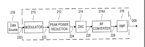
For example, referring to Figure 12, the transmitter 110 of the present
embodiment includes a signal processing system 208 for processing a signal,
such as
for communication via the communication system 100. In the present embodiment,
the signal processing system 208 includes a modulator 210, a peak-power
reduction
component 212, a digital-to-analog converter (DAC) 214, an RF converter 214A,
and
an amplifier 216. The modulator 210 receives digital information 220 from one
or
more data sources 218 and generates a baseband modulated signal 222.
In various embodiments, the peak-power reduction component 212 is
configured to receive the modulated signal 222 from the modulator 210 and
substantially reduce the peak power output requirement of the transmitter 110.
The
peak-power reduction component 212 may be additionally configured to inhibit
spectral regrowth or other frequency components outside one or more desired
bandwidths. In addition, the peak-power reduction component 212 may be farther
22
CA 02650209 2008-10-21
WO 2007/127782
PCT/US2007/067388
configured to inhibit or minimin the addition of noise to the signal to
maintain an
acceptable signal-to-noise ratio and/or remain within relevant error vector
magnitude
(EVM) constraints.
The DAC 214 is configured to receive a peak-reduced digital signal 224 from
the peak-power reduction component 212 and convert the digital signal into an
analog
signal 226. The RF converter 214A translates the analog signal from a lower
frequency (near or at baseband) to the desired RF transmission frequency prior
to
amplification. The amplifier 216 amplifies the analog RF signal 228 prior to
transmission to the receiver 112. Additional distortion-compensation
processing may
be performed after the peak-power reduction component 212 and prior to the DAC
214.
The modulator 210 may comprise any suitable system for modulating a digital
signal. Referring to Figure 13, an exemplary modulator 210 comprises a
conventional
digital modulator and generates a baseband modulated multi-channel signal 222.
The
modulator 210 suitably comprises a multi-channel modulator for receiving
multiple
data streams, modulating the data stream for each channel and frequency
translating
the modulated signal to an appropriate offset frequency, and summing the
various
channel outputs into a composite output signal. The modulator 210 may be
configured, however, in any suitable manner, for example as a single-channel
modulator. The present exemplary modulator 210 comprises one or more baseband
modulators 312 and one or more digital synthesizers 314. Each baseband
modulator
312A-D converts data into a baseband wavefoim according to an appropriate
modulation, such that each baseband modulator 312A-D converts information
bits,
such as compressed binary digital data corresponding to voice, data, or video
signals,
into a corresponding baseband digital waveform 316A-D. The baseband digital
23
CA 02650209 2008-10-21
WO 2007/127782
PCT/US2007/067388
waveforms 316A-D may comprise any suitable waveforms, such as waveforms in
accordance with a selected transmission encoding specification, such as GSM,
spread
spectrum, TDMA, CDMA, or the like. In an exemplary embodiment, the baseband
digital waveforms 316A-D comprise time-varying sequences of complex pairs
having
an in-phase component (I) and a quadrature component (Q) occurring at a defmed
sample rate.
In various embodiments, each digital synthesizer 314A-D generates a complex
digital local oscillator (LO) signal that multiplies the baseband digital
waveform to
generate offset-frequency modulated signals 322, which are then combined to
form
the baseband multi-channel signal 222. The digital synthesizer 314 may
comprise any
appropriate source of a digital carrier frequency or other signal to generate
the
individual offset-frequency modulated signals 322A-D. In the present exemplary
embodiment, the digital synthesizer 314 comprises a conventional multiple-
output
digital synthesizer configured to provide several different LO signals 318A-D
at
different offset frequencies. These frequencies may, for example, correspond
to offset
frequencies for accepted transmission frequencies for a particular cellular or
wireless
network, or other communication spectral mask. In the present exemplary
embodiment, the digital synthesizer 314 may suitably generate complex-
exponential
("cisoid") signals 318A-D at the desired offset frequencies for the individual
offset-
modulated modulated signals 322A-D for each channel. In this embodiment of the
present invention, the digital synthesizer output signal 318 is multiplied
with the
baseband digital waveform 316 for the relevant channel via a multiplier, thus
translating each baseband waveform to the proper channel offset frequency,
thus
constituting the individual offset-frequency modulated signals 322A-D. The
various
24
CA 02650209 2008-10-21
WO 2007/127782
PCT/US2007/067388
offset-frequency modulated signals 322A-D may be summed to form the composite
baseband modulated signal 222.
Referring again to Figures 11 and 12, in an exemplary embodiment of a peak-
power reduction component within the scope of the present invention, the
composite
baseband modulated signal 222 is provided to the peak-power reduction
component
212 from the MCS modulator 210. The peak-power reduction component 212 may be
configured in any suitable manner to reduce the peak power output of the
transmitter
110, such as by subtracting portions of the signal exceeding a threshold from
the
signal. The peak-power reduction component 212 may also inhibit transmission
of
unwanted spectral energy, for example frequency components outside a
regulatory
spectral mask. The peak-power reduction component 212 receives the baseband
modulated signal 222 from the modulator 210 and processes the baseband
modulated
signal 222 according to any suitable process. For example, referring to Figure
4, the
peak-power reduction component 212 may be configured to generate an excursion
signal in response to a peak portion 410 in the baseband modulated signal 222
having
a magnitude beyond a defined magnitude threshold 412. The peak-power reduction
component 212 suitably removes or reduces the peak portion 410 from the
baseband
modulated signal 222 in response to the excursion signal.
Referring to Figure 14, an exemplary embodiment of a peak-power reduction
component 212 according to various aspects of the present invention comprises
a
delay element 510, an interpolator 502, an excursion signal generator 512, a
scaling
system 820, an excursion filter system 514, and an excursion reducer 544. The
excursion signal generator 512 generates an excursion signal 410 in response
to the
baseband modulated signal 222 exceeding the magnitude threshold 412 as shown
in
Figure 4. The output 410 of the excursion signal generator 512 may also be
scaled by
CA 02650209 2008-10-21
WO 2007/127782
PCT/US2007/067388
scaling system 820 prior to being processed by the excursion filter system
514. As
shown in Figure 14, the excursion filter system 514 filters unwanted
frequencies from
the signals produced by the excursion signal generator 512. An excursion
reducer 544
subtracts the scaled and filtered excursion signal from the suitably delayed
baseband
modulated signal 222. The delay element 510 compensates for propagation time
delay through the excursion signal generator 512 and the excursion filter
system 514
so that the signal from the filter system 552 is time-aligned with the delayed
baseband
modulated signal 222.
The excursion signal generator 512 shown in the peak-power reduction
component of Figure 14 may be configured in any suitable manner to generate an
excursion signal 410 responsive to peak portions of the baseband modulated
signal
222 or other relevant signal. A suitably scaled and filtered version of the
excursion
signal 410 may then be subtracted from or otherwise used to reduce one or more
peaks in the original signal. Moreover, the excursion signal 410 may be used
in any
suitable manner to reduce the peak power of the original signal. Referring to
Figure
15, an exemplary excursion signal generator 512 comprises a magnitude
calculation
circuit 810, a threshold circuit 812 (not shown), a peak parser 910 and a
waveform
generator 814. The output 410 of the excursion signal generator 512 is fed
into the
scaling system 820. The peak parser 910 identifies individual magnitude peaks
in the
signal 222, and the waveform generator 814 generates the excursion signal 410
in
response to the identified peaks. In one embodiment, the excursion signal
generator
512 receives the baseband modulated signal 222 and calculates magnitude
values,
such as successive magnitude values of the baseband modulated signal 222 based
on
the successive signal complex pairs. The excursion signal generator 512
compares
the magnitude of samples of the signal 222 to the magnitude threshold 412. The
26
CA 02650209 2008-10-21
WO 2007/127782
PCT/US2007/067388
excursion signal generator 512 generates the excursion signal 410 in response
to the
portions of the baseband modulated signal 222 that exceed the magnitude
threshold
412. In yet another exemplary embodiment, the excursion signal generator 512
is
configured to generate an excursion signal 410 that corresponds to the full
duration
(or full set of samples) of the baseband modulated signal 222 that exceeds the
magnitude threshold 412, though the excursion signal generator 512 may be
configured to generate an excursion signal 410 corresponding to any aspect of
the
signal exceeding the magnitude threshold 412.
Referring to Figure 16, an exemplary excursion signal generator 512
comprises a magnitude calculation circuit 810, a threshold circuit 812 and a
waveform
generator 814, whose output 410 is the input to common-mode (as opposed to
channel-specific) scaling system 820. The magnitude calculation circuit 810
calculates the magnitude of the baseband modulated signal 222 and generates a
corresponding magnitude signal 816. The magnitude calculation circuit 810 may
be
implemented in any suitable manner to determine the magnitude of samples of
the
baseband modulated signal 222, such as a conventional circuit configured to
calculate
the magnitude according to the following equation:
M(11) = R2(n) Q2(n)i1/2
Where M(n) is the magnitude of the baseband modulated signal 222 for a complex
sample pair at sample n, I(n) is the in-phase component of the signal for the
complex
sample pair I, and Q(n) is the quadrature component of the signal for the
complex
sample pair I. The magnitude calculation may be performed, however, according
to
any suitable technique or algorithm.
In the present embodiment as illustrated in Figure 16, the magnitude signal
816 is provided to the threshold circuit 812, which compares the calculated
magnitude
27
CA 02650209 2008-10-21
WO 2007/127782
PCT/US2007/067388
to the magnitude threshold 412 and generates a corresponding comparison signal
818.
The threshold circuit 812 may comprise any suitable system for comparing the
magnitude of the baseband modulated signal 222 to the threshold. For example,
the
threshold circuit 812 may comprise a conventional comparator circuit or
subtraction
circuit.
The magnitude threshold 412 may comprise any suitable value and/or signal.
For example, the threshold value may comprise a static value, such as one
corresponding to the maximum power of the amplifier 216 or a power level
slightly
lower than the maximum power. Thus, the comparison signal 818 designates
samples
of the signal 222 corresponding to RF signal values that would exceed the
maximum
power level of the amplifier 216 or other suitable threshold. Alternatively,
the
magnitude threshold 412 may be a dynamic value. The magnitude threshold 412
may
be adjusted according to any suitable criteria. For example, the magnitude
threshold
412 may be calculated as a function of the signal power for the various
channels
and/or the amount of noise in the signal. Thus, if two channels are operating
at
maximum power and two other channels are operating at half the maximum power,
the magnitude threshold 412 may be set at 75% of the maximum power. If the
amount of noise in one or more channels approaches and/or exceeds a limit,
such as
the EVM threshold, the magnitude threshold 412 may be increased. Conversely,
if
the amount of noise is lower, the magnitude threshold 412 may be further
decreased.
Any suitable criteria or algorithm, however, may be used to select the
magnitude
threshold 412.
The communications system 100 may be configured to take advantage of the
reduced peak-power requirements due to the peak-power reduction component 212.
For example, the communications system may be designed or reconfigured to use
a
28
CA 02650209 2008-10-21
WO 2007/127782
PCT/US2007/067388
lower-power amplifier to transmit signals. In addition, the communications
system
100 may be configured to use the additional power made available by the peak-
power
reduction component 212 to improve the link between the transmitter 110 and
the
receiver 112 and/or expand the coverage of the signal.
For example, the magnitude threshold 412 may be set at a selected level to
reduce the overall peak-power demand of the transmitter 110. The average
transmitted signal power may then be boosted so that the peak-power
transmitted by
the system returns to its original level, but with a higher average power of
the
transmitted signal. For example, if the threshold is originally set to reduce
the peak-
power requirement by 3 dB, the transmitted power of the peak-reduced signal
may be
increased by 3 dB to match the original peak-power. Thus, the same amplifier
may be
used to transmit a higher average power signal, thereby enhancing link
quality. The
magnitude threshold 412 may also be dynamically changed to reduce overall
power
consumption.
Reducing the level of the magnitude threshold 412 may raise the noise level in
the transmitted signal. In many applications, however, the noise in the
transmitted
signal is relatively low compared to the ordinary noise level at the receiver,
for
example thermal noise. As a result, because the noise level has only slightly
increased while the power of the transmitted signal has significantly
increased, the
signal-to-noise ratio (SNR) at the receiver tends to improve.
In various environments, the reduction of the magnitude threshold 412 to
boost the transmission power may be unacceptable, for example by causing the
SNR
at the transmitter to contravene standards that may apply. For example, the
current
IEEE 802.16 standard requires the transmitter SNR to be no less than 19.6 dB.
If the
magnitude threshold 412 for the transmitter 110 is reduced beyond a point, the
29
CA 02650209 2008-10-21
WO 2007/127782
PCT/US2007/067388
induced noise from generating the excursion may cause the SNR to drop below
the
19.6 dB minimum, despite the improved overall quality of the link. In such
environments, the improved link quality may be implemented as an option. For
example, the transmitter 110 and receiver 112 may be configured to initially
operate
in accordance with the relevant standard. The transmitter 110 and receiver 112
may
communicate to establish whether the other may operate using the improved
quality
link. If the units share the ability to communicate with the improved quality
link, the
transmitter 110 and receiver 112 may be reconfigured, either manually or
automatically, to reduce the magnitude threshold 412 to the lower level and
boost the
respective transmission levels.
In one embodiment, the threshold circuit 812 monitors the EVM value for
each channel and adjusts the magnitude threshold 412 to minimize signal peaks
(i.e.
maximize peak-reduction) while remaining within EVM specifications. If the
noise is
low enough that the measured EVM value is below the relevant limit, the
threshold
circuit 812 decreases the magnitude threshold 412. If the EVM magnitude
approaches or exceeds the relevant limit, the threshold circuit increases the
magnitude
threshold 412.
Referring again to Figure 16 and continuing with the description of the
implementation details of the various exemplary embodiments, the comparison
signal
818 is provided to the waveform generator 814. The waveform generator 814
generates the excursion signal 410 according to the comparison signal 818. The
waveform generator 814 may be configured in any suitable manner to generate
the
excursion signal 410, such as a conventional subtraction circuit to subtract
the
magnitude threshold 412 value from the magnitude component of the baseband
modulated signal 222. Another exemplary method for generating the excursion
would
CA 02650209 2008-10-21
WO 2007/127782
PCT/US2007/067388
employ the CORDIC algorithm. See, e.g., Ray Andraka, "A Survey of CORDIC
Algorithms for FPGA-based Computers," Proceedings of the 1998 ACM/SIGDA
Sixth International Symposium on Field Programmable Gate Arrays, Feb. 22-24,
1998, Monterey, CA, pp. 191-200. Preferred CORDIC algorithm usage involves a
series of phase-rotation operations to rotate the original signal vector (i.e.
sample) to
an equivalent-magnitude zero-phase vector, while simultaneously performing
conjugate phase rotation operations on a vector initialized to zero-phase and
magnitude equal to the magnitude threshold 412; the excursion sample equals
the
difference between this resultant vector and the original complex vector if
the original
signal magnitude is greater than the magnitude threshold 412, and equals zero
otherwise. The operations of the threshold circuit 812 and the waveform
generator
814 may be performed by a single circuit or system, such as a subtraction
circuit
configured to perform the comparison to the magnitude threshold 412 and
generate
the waveform by subtracting the magnitude threshold 412 from the magnitude of
the
baseband modulated signal 222. If the comparison signal 818 indicates that the
magnitude signal 816 does not exceed the magnitude threshold 412, the waveform
generator 814 may generate a null signal. If the comparison signal 818
indicates that
the magnitude signal 816 exceeds the magnitude threshold 412, the waveform
generator 814 generates a signal having a magnitude corresponding to the
difference
between the magnitude of the baseband modulated signal 222 and the magnitude
threshold 412, and phase being identical to the baseband modulated signal. The
resulting excursion signal may then be filtered, scaled, and subtracted from a
suitably
delayed version of the baseband modulated signal 222 to reduce signal peaks.
In various embodiments, a common-mode scaling system 820, as shown in
Figure 16, may be provided and configured to adjust the magnitude of the
generated
31
CA 02650209 2008-10-21
WO 2007/127782
PCT/US2007/067388
(excursion) waveform so that the resulting scaled excursion signal, after
filtering,
reduces peaks in the baseband modulated signal 222 that initially exceed the
magnitude threshold so that they equal a selected value, generally the
magnitude
threshold value. The common-mode scaling system 820 receives the unsealed
excursion signal 410 from the waveform generator 814 and selectively adjusts
the
magnitude of the excursion samples to generate the scaled excursion signal
516. The
system 820 may scale the excursion signal 410 according to any suitable
process and
may be implemented in any suitable manner. For example, the system 820 may be
configured to selectively adjust the unsealed excursion signal 410 such that
the
maximum magnitude of the peak-reduced signal 224 does not exceed the selected
magnitude threshold. For example, if the magnitude threshold 412 for a
particular
system is 1.8 and the magnitude of the baseband modulated signal 222 is 4.0,
the
common mode scaling system 820 is suitably configured to scale the peak
magnitude
of the corresponding sample generated by the peak power reduction component
212,
such as a scaled and filtered excursion signal 552 (as shown in Figure 14), to
2.2. In
still another example, the common mode scaling system may be configured to
scale
the excursion signal based on the ratio of the peak magnitude of the
unfiltered
excursion signal 410 to the peak magnitude of the filtered excursion signal
410B. As
discussed above, this ensures that the scaled and filtered excursion peak
magnitude
substantially matches the original excursion peak magnitude. As can be
appreciated,
any implementation which achieves the desired objective of adjusting the
magnitude
of the generated waveform so that the filtered excursion signal reduces the
signal peak
to a defined threshold level or below is within the scope of the present
invention.
With reference to Figure 10, an excursion event 2310 may include multiple
peak events 2312. The boundaries between the peak events 2312 may be defined
32
CA 02650209 2008-10-21
WO 2007/127782
PCT/US2007/067388
according to any suitable criteria. Peak events 2312 are separated by a trough
sample
2314, which may be defined as an excursion event sample having higher
magnitude
samples on each side. A peak event 2312 may be defined as a set of excursion
samples for which the magnitude of immediately adjacent samples are either
lower
than the magnitude threshold 412 (at an excursion boundary) or higher than the
magnitude of the trough between two peak-events). The common-mode scaling
system 820 may thus suitably apply a selected scaling value to every sample of
a
particular peak event 2312, for example according to the magnitude of the
highest
magnitude sample in the pre-filtered peak event, the post-filtered peak event,
or both.
Thus, all of the samples between two troughs 2314 (or between the beginning of
the
excursion 2316 and the first trough 2314 or between the last trough 2314 and
the end
of the excursion 2318) are scaled using the same scaling factor, which is
suitably
selected according to the highest magnitude samples in the group of samples
constituting the peak events 2312 of an excursion event 2310.
Thus, in various embodiments, as illustrated, for example, by Figure 15, peak
parser 910 may be provided and configured in any suitable manner to identify
peaks
in the incoming signal, such as via the magnitude signal from the magnitude
calculation circuit 810. In one embodiment, the peak parser 910 comprises a
peak
detector 920 and a buffer 922. The peak detector 920 identifies a peak in the
incoming signal in any suitable manner, such as by comparing the magnitudes of
successive complex pairs in the incoming signal.
In the present embodiment, the peak detector 920 provides a signal to the
buffer 922 when a peak is detected in the incoming signal samples. The buffer
922 is
suitably configured to temporarily store the incoming signal while the peak
detector
920 identifies the peaks in the incoming signal. The buffer 922 may comprise
any
33
CA 02650209 2008-10-21
WO 2007/127782
PCT/US2007/067388
suitable storage element, such as a FIFO buffer having an appropriate number
of
storage elements. When a peak is detected, the buffer 922 suitably provides
the
relevant data to the waveform generator 912. In the present embodiment, the
waveform generator 814 is configured to generate an =scaled waveform in
response
to the detected peak in the incoming signal samples.
As shown in Figure 17, the peak parser 910 may also be suitably configured to
route the individual peaks to different scaling systems for processing. For
example,
when a first peak is identified, the peak parser 910 suitably transmits the
peak event
samples to a first scaling system 820A, and the next peak event samples may be
transmitted to a second scaling system 820B, and the following peak event
samples
back to the first scaling system 820A or an additional scaling system. After
scaling,
the scaled samples may be recombined to form a single scaled excursion signal
516.
Using different scaling systems 820A-B to process consecutive peaks may
advantageously reduce inter-peak processing interference which may result from
use
of a single scaling system 820. Multiple scaling systems 820 may be
implemented
depending on processing system performance objectives.
In various embodiments, as shown illustratively in Figure 14, the scaled
excursion signal 516 is provided to the excursion filter system 514 to
eliminate
unacceptable spectral energy, such as frequency components induced by the
excursion
signal generator 512. The frequencies to be filtered may be selected according
to any
suitable criteria. Even though the excursion signal resembles unchannelized
broadband noise spanning approximately 3x the bandwidth of the linear
channelized
signal, we may conceptualize it as consisting of two distinct components:
spectral
energy that cannot appear at the peak-reduction node 544 without violating EVM
specifications; and all other excursion spectral energy; the role of the
excursion filter
34
CA 02650209 2008-10-21
WO 2007/127782
PCT/US2007/067388
system is to separate these components, passing the latter while eliminating
the
former. The excursion signal thus "contains" the channelized excursion energy
(allowable spectral energy) as one component, and it is this component which
is
allowed to pass (with suitable scaling) by the excursion filter system. That
is, the
excursion signal can be considered as being comprised of two distinct
components:
(1) the allowable spectral energy; and (2) the unallowable spectral energy.
However,
there is no physical distinction between the allowable and unallowable
spectral energy
components until the excursions filter system applies channel filtering, i.e.,
the
excursion is not channelized until filtering is applied. In the present
embodiment,
spectral energy is attenuated or eliminated at any frequencies other than
those
approved by the applicable regulatory spectral mask. In systems having
multiple
spectral energy levels across a particular signal passband, the excursion
filter system
514 may be configured to adjust the relative spectral energy levels across the
passband to approximately match the in-band variations. For example, if one
portion
of a channel's average power spectrum is 10 dB lower than the rest of the
power
spectrum, as might be the case when the channel consists of adjacent sub-
channels,
the excursion filter system 514 may introduce a matching 10 dB relative
attenuation
of the excursion spectrum across the same frequency range.
The excursion filter system 514 may be configured in any suitable manner to
substantially filter the unwanted frequencies and transmit the desired
frequencies, or
otherwise promote the transmission of desired frequencies and/or attenuate
unwanted
frequencies. For example, the excursion filter system 514 is suitably
configured to
separate the scaled excursion signal 516 into individual frequency components
corresponding to the input channels. The excursion filter system 514 filters
individual
components of the excursion signal corresponding to baseband modulated signal
222
CA 02650209 2008-10-21
WO 2007/127782
PCT/US2007/067388
to eliminate any unacceptable power spectral energy. Alternatively, the
excursion
filter system 514 may be configured as a bandpass or bandstop filter to pass
or
attenuate power spectral energy at selected frequencies, or otherwise
configured to
alter the distribution of power spectral energy over a defined frequency
range. In
addition, the excursion filter system 514 may comprise multiple filter
systems, such as
a cascade of filters or a set of parallel filters.
In the present exemplary embodiment, the excursion filter system 514
comprises multiple parallel channel filters 518 whose outputs are summed
together.
Each channel filter 518 suitably comprises a conventional digital filter for
reducing
excursion signal power at selected frequencies corresponding to the particular
channel. For example, each channel filter 518 may include a down-converter
520, a
low pass filter 522, a channel-specific gain-adjustment 540, and an up-
converter 524,
and each channel filter 518 suitably operates in a similar manner. Referring
to
Figures 14 and 18A-C, the down-converter 520 receives the scaled excursion
signal
516, which exhibits a wide range of frequencies fs (Figure 18A). The down-
converter
520 shifts the frequency of the entire input spectrum to the left or right,
such as by an
amount substantially corresponding to the center/offset frequency fA of the
relevant
channel. The low pass filter 522 filters input signals to substantially
eliminate signal
energy above a selected cutoff frequency fc and substantially transmit signals
below
the selected cutoff frequency (Figure 18B). The up-converter 524 shifts the
frequency
of the filtered signal to a higher frequency, such as to a selected frequency
or by a
selected amount. In the present embodiment, the up-converter 524 shifts the
center
frequency by an amount substantially corresponding to the center frequency of
the
relevant channel, i.e. back to the original center/offset frequency (Figure
18C).
36
CA 02650209 2008-10-21
WO 2007/127782
PCT/US2007/067388
Outputs 542 from the various channel filters 518 are then combined into a
composite
signal 552 by a filtered signal summer 550.
As shown schematically in Figure 14, an exemplary down-converter 520 for
the present embodiment comprises a multiplier 526 and a complex conjugate
generator 528. The complex conjugate generator 528 receives the relevant
digital
synthesizer signal 318 from the relevant digital synthesizer 314 and generates
a
complex conjugate signal 530 corresponding to the complex conjugate of the
digital
synthesizer signal 318. The multiplier 526 multiplies the complex conjugate
signal
530 with the scaled excursion signal 516. The resulting frequency-shifted
signal 536
is a substantially identical waveform as the scaled excursion signal 516, but
frequency-shifted by an amount substantially equal to the negative of the
channel's
offset frequency.
In the present embodiment, the frequency-translated signal 536 is provided to
the low-pass filter 522. The low-pass filter 522 may be implemented in any
suitable
manner and may be configured to use any suitable cutoff frequency. For
example, the
low-pass filter may comprise a single filter, multiple parallel filters, or a
cascade of
filters. In the present embodiment, the low-pass filter 522 comprises a
digital low-
pass filter, such as a finite impulse response filter, having a cutoff
frequency
corresponding to one-half the approved bandwidth of the relevant channel. For
example, if the approved channel frequency range is 20 MHz to 20.5 MHz, the
cutoff
frequency may be set at one-half of the 500 kHz bandwidth, or at 250 kHz. The
digital low pass filter 522 thus transmits a filtered signal 538 comprising
the
components of the down-adjusted signal 536 that are below the cutoff frequency
and
attenuates spectral components above the cutoff frequency. The low pass filter
522
37
CA 02650209 2008-10-21
WO 2007/127782
PCT/US2007/067388
suitably comprises an approximately linear phase filter to minimize the amount
of
phase and/or magnitude error induced by the filter.
In a communications system using subchannels within the various channel
passbands, such as an OFDIVIA environment each channel filter 518 may include
one
or more bandpass or bandstop filters for filtering unwanted frequencies. For
example,
referring to Figure 19, the various channels of baseband modulated signal 222
may
include sub-channels at different frequencies within the channel, such as in
an
OFDMA system. Each such channel filter 518 suitably includes multiple bandpass
filters or series of bandstop filters 1710 for each sub-channel configured to
filter
frequencies other than the sub-channel frequency. This sub-channel filtering
may be
preferentially implemented using the fast fourier transform (FFT),
In addition, the gain of each sub-channel filter 1710 may be adjustable to
control the magnitude of the particular sub-channel, for example to facilitate
adjustment of the relative sub-channel spectral energy levels across the
passband to
approximately match the in-band variations, or to comply with sub-channel EVM
constraints. For example, referring to Figure 20, the baseband modulated
signal 222
may comprise multiple main channels 1810, each of which includes multiple sub-
channels 1812. Each sub-channel filter 1710 suitably operates as a magnitude
adjustment circuit to adjust the gain for the sub-channel to reduce
interference
between sub-channels, such as by adjusting the sub-channel filter 1710
magnitudes
according to the relative average signal power magnitudes of the corresponding
sub-
channel. Thus, the sub-channel filter 1710 may provide greater attenuation of
the
sub-channel excursion signal for a lower magnitude sub-channel signal, which
tends
to reduce the interference attributable to the higher energy levels in the
adjacent sub-
channels, and may be critical to comply with sub-channel EVM constraints.
38
CA 02650209 2008-10-21
WO 2007/127782
PCT/US2007/067388
In the present exemplary embodiment involving frequency shifting shown in
Figure 14, the filtered channel signal 538 is transmitted to the up-converter
524 for
conversion back to the original channel frequency offset. In the present
embodiment,
the frequency-converter 524 comprises a multiplier 532 which multiplies the
filtered
signal 538 with the digital synthesizer signal 318 from the digital
synthesizer 314 to
return the filtered signal 538 to the original channel frequency offset, and a
phase-
shifter 534 required to compensate for processing-induced delay.
The signal processing system may also be configured to adjust the magnitude
and/or phase of the filtered signal 538. Because the filtered excursion is to
be
subtracted from the baseband modulated signal 222, the filtered excursion is
suitably
configured to exactly match the portion of the baseband modulated signal 222
that
exceeds the threshold 412. Channel filtering may alter its passband magnitude
and
phase relative to the baseband modulated signal 222. Infinite-impulse response
(IIR)
filtering may be used to reduce the filter complexity relative to that
required using
finite-impulse-response (FIR) filtering; however, IIR filtering introduces
nonlinear
phase distortion and passband magnitude ripple in the signal passband that can
degrade peak-reduction, Further, the magnitude of the filtered signal 538 may
be
adjusted to conform to transmission requirements or other considerations.
Consequently, the signal processing system may be configured using an
equalizer to
adjust the passband magnitude and/or phase of the filtered signal 538 to
reduce
passband distortion in the channel filter. The equalization function is
suitably
integrated into the low pass filter system 522, or may comprise a separate
equalization
circuit 566 for processing the filtered signal 538. The low pass filter 522
suitably
comprises an FIR or equalized-IIR low pass filter. Low pass filter 522 is a
single
39
CA 02650209 2008-10-21
WO 2007/127782
PCT/US2007/067388
channel's LPF, whereas the impulse response of interest in computing common-
mode
scaling is that of the entire excursion filter system 514.
Phase equalization causes the composite phase shift as a function of the
frequency for the cascade of the channel filter and the equalizer to be as
close to linear
as possible. The phase equalization function is suitably implemented as an all-
pass
filter (i.e. all magnitudes are passed with unity magnitude) whose phase-shift-
vs-
frequency characteristic can be adjusted. The phase equalizer is suitably
configured
to compensate for phase shifts induced by the low pass filter 522 and/or any
other
sources of unwanted phase shifts. Magnitude equalization addresses passband
magnitude ripple distortion by adding a cancellative passband magnitude
ripple, such
that the net ripple (i.e. product of the cascaded magnitude effects) is
reduced.
In the present exemplary embodiment as shown schematically in Figure 14,
each individual channel filter 518 also includes a dedicated phase correction
element
534 to compensate for the phase shift introduced by frequency conversion
operations
and processing propagation delay. The phase correction element 534 suitably
adjusts
the phase (in radians) of the filtered signal 538 according to the radian
frequency (in
rad/sec) of the digital synthesizer signal 318 from the digital synthesizer
314
multiplied by the duration (in seconds) of the propagation delay through the
channel
filter 518. For example, the phase correction element 534 may adjust the phase
of the
digital synthesizer signal 318 prior to using it to up-convert the filtered
excursion
energy. This channel-specific phase shift assures that a channel filter 518
input
sinewave in the channel passband will exit from that channel filter with no
change in
magnitude or phase.
In an exemplary embodiment including frequency shifting, the resulting
frequency-converted, phase-adjusted scaled and filtered excursion 552
comprises a
CA 02650209 2008-10-21
WO 2007/127782
PCT/US2007/067388
waveform corresponding to the scaled excursion of the baseband modulated
signal
222 beyond the threshold magnitude. Due to the filtering, the phase-adjusted
filtered
signal 552 only an acceptable amount of spectral energy outside the approved
bandwidth.
One purpose of the present inventive concept is that the scaled excursion
signal 516 is provided to the excursion filter system 514 to remove any
components in
the scaled excursion signal 516 outside of the approved channel bandwidths. In
particular, the scaled excursion signal 516 is provided to each down-converter
520,
which translates the center frequency of the signal from each channel offset
frequency
to baseband. The frequency-translated signal 536 is then provided to the low-
pass
filter 522, which filters out frequencies above the cutoff frequency. In the
present
embodiment, the cutoff frequency corresponds to one half the bandwidth of the
approved bandwidth. The filtered signal 538 is then adjusted by the up-
converter 524
to frequency-translate the signal to the original channel offset frequency.
The filtered
signal, including sub-channels within a particular passband or channel, may
also be
processed for phase and magnitude adjustment to compensate for changes induced
by
the excursion signal generator 512 and the excursion filter system 514.
In a system using sub-channels, each channel filter 518 may adjust the
magnitude of the various sub-channel filters according to the magnitudes of
the sub-
channels in the signal. Consequently, sub-channel signals in the excursion
signal
having lower magnitudes are subjected to greater attenuation than those having
greater magnitudes. In a time division environment, each channel filter 518
may
adjust the magnitude of the various channel filter gain-adjustments in a
manner
dependent on the time slots for the excursion signal according to the
magnitudes of
the signals in those time-slots in the baseband modulated signal 222. Thus,
excursion
41
CA 02650209 2008-10-21
WO 2007/127782
PCT/US2007/067388
channel time slots corresponding to signal channel time slots having lower
energy
magnitudes are subjected to greater attenuation than excursion channel time
slots
corresponding to signal channel time slots having greater energy magnitudes.
Each
channel filter 518 may also apply a smoothing window to the filtered excursion
signal
generated by that channel filter.
The composite filtered signal 552 comprises a waveform corresponding to the
waveform of the excursion beyond the threshold in the baseband modulated
signal
222. By filtering the excursion signal, unwanted frequency components, such as
those attributable to spectral regrowth or other signal processing effects,
may be
eliminated from the composite filtered excursion signal 552. When this
composite
filtered signal 552 is subtracted from the delayed baseband modulated signal
222 by
the excursion reducer, the resulting peak-reduced signal 224 tends to exhibit
maximum peak magnitudes that are essentially equal to the magnitude threshold
and
exhibit few or no unwanted frequency components introduced by the peak-power
reduction component 212. Consequently, the peak-power of the signal decreases,
facilitating use of a lower cost amplifier 216 while satisfying all regulatory
spectral
constraints (masks) and minimizing distortion to the original signal.
In addition, the peak-reduction component 212 need not precisely determine
the instant at which an excursion peak occurs, or the precise amplitude and
phase
value of the peak, as is critical in many alternative approaches. E.g., T. May
and H.
Rohling, "Reducing the Peak-To-Average Power Ratio in OFDM Radio Transmission
Systems," Proc. 1998 Vehicular Tech. Conf., vol. 3, pp. 2474-78, May 18-21,
1998.
Peak-reduction techniques that subtract a scaled and time-aligned version of a
constant band-limited pulse shape from the original signal are known to
exhibit high
sensitivity to errors in determining the precise magnitude, phase and precise
instant at
42
CA 02650209 2008-10-21
WO 2007/127782
PCT/US2007/067388
which the peak occurs, forcing high over-sampling to mitigate this
degradation, as
described by M. Lampe and H. Rollling, "Reducing Out-of-Band Emissions Due to
Nonlinearities in OFDM Systems," 49th IEEE Conference on Vehicular Technology,
16-20 May, 1999, pp. 2255-2259. The alternative method described herein
completely eliminates this critical sensitivity by processing a multi-sample
portion
(i.e. peak-event) of the excursion waveform; each individual peak event is
scaled,
filtered and subtracted from the baseband modulated signal 222 with
corrections for
delays and equalization. Further, the peak-power reduction component suitably
operates in the same manner, regardless of the number of input signals. The
substantial peak-reduction performance improvement using the new approach is
directly attributable to eliminating the prior art's limitation of scaling a
constant
(band-limited) pulse shape; the highly variable shape of signal peaks demands
generation of an optimal cancellation waveform (i.e. filtered and scaled peak-
event)
for each individual signal peak.
The composite filtered signal 552 may be provided to the excursion reducer
544 or subjected to further processing. Additional processing may comprise any
suitable processing, such as to improve the signal or adapt the signal to a
particular
environment. For example, the composite filtered signal 552 may be processed
using
further peak-power reduction processing or filtering, such as via another peak-
power
reduction component 212. The signal may exhibit slight variation in the
maximum
magnitude of its peaks due to filter response in the preceding peak-power
reduction
processing, scaling misadjustments, or other sources. Repetitive peak-power
reduction processing reduces such variation.
Referring to Figure 14, the filtered signal 538 may also be further processed
according to any desired criteria. For example, the filtered signal 538 may be
43
CA 02650209 2008-10-21
WO 2007/127782
PCT/US2007/067388
provided to a channel scaling/gain control element 540, for example between
the
channel lowpass filter (LPF) filter 522 and the up-converter 524. Such a
channel
scaling circuit may be used in the excursion-reduction approach of the present
invention as illustrated, for example, by Figure 21.
In one embodiment, the channel gain control element 540 may adjust the
relative signal energy for the multiple signals to control the amount of in-
band noise
added to either the overall signal or any individual channel. For example, the
channel
gain control element 540 may be responsive to basestation control signals that
adjust
the transmission power for a particular channel, such as according to the
estimated
attenuation between the transmitter 110 and the receiver 112.
In an alternative embodiment, the channel gain control element 540 may
adjust the magnitude of the filtered signal 538 to control the amount of noise
added to
the signal that may be caused by the peak-power reduction component 212. For
example, in cellular communications, the acceptable amount of noise that may
be
added to a particular channel is typically constrained by error vector
magnitude
(EVM) specifications. The peak-power reduction component 212, however, may add
noise to one or more channels. For example, peak reduction may add noise to a
lower
power channel. To reduce the added noise, the channel gain control element 540
may
adjust the amount of peak-power reduction applied to the lower power channel
by
adjusting the gain applied to the filtered signal 538 for that channel.
Figure 22 depicts a preferred embodiment of a functional architecture of a
peak-reduction processing algorithm within the scope of the present invention
and
which may be further implemented according to the various configurations
described
above. The composite multi-channel (MCS) baseband modulated signal 222 splits
into two paths: the bottom path computes the optimal peak-reduction
cancellation
44
CA 02650209 2008-10-21
WO 2007/127782
PCT/US2007/067388
waveform, whereas the top path simply delays the original signal so that the
peak-
reduction signal is properly time-aligned. The interpolator 502 is suitably
interposed
to expand the digital spectrum adequately so that the nonlinear spectral
components
created during excursion generation (an intrinsically nonlinear operation)
remain
adequately isolated from the original signal spectrum. For purposes of the
present
description, it is assumed that the sample rate of the MCS waveform is
sufficient to
satisfy the Nyquist-Shannon sampling theorem for the original baseband signal.
In
this case, since the bandwidth of the excursion signal will be at least three
times that
of the corresponding baseband signal, an interpolator 502 must increase the
sampling
rate by at least a factor of three. Interpolator 502 combines the functions of
increasing
the sampling rate of the signal, as well as filtering off any spectral
'images' created in
this process. Occasionally, the sampling rate of the original signal might be
increased
to facilitate sample rate conversion, in which case the additional explicit
interpolator
502 might be unnecessary. It is critical however, that the sample rate at the
input to
the excursion generator be at least three times that of the Nyquist-Shannon
sampling
rate required to represent the baseband MCS signal. The excursion signal, a
complex
baseband signal, is then split into two paths to facilitate scaling
processing.
The output signal 504 of the interpolator is input to the excursion generator
512. The excursion signal 410 is generated by reference to a magnitude
threshold
level 412. The path from the excursion generator leads to the peak parser 910,
which
is part of the common-mode scaling system 820. The peak parser 910 parses the
set
of contiguous complex samples corresponding to each isolated excursion event
into
sets of complex peak event samples as illustrated in Figure 10. As noted, the
minimum-magnitude (i.e. 'trough') sample point, for example, may be
arbitrarily
assigned to either the preceding or trailing peak event. In a particular
embodiment,
i
CA 02650209 2012-02-15
the parsed peak events are used to compute an optimal (real) scaling factor
that
is applied to each sample within each peak event. The embodiment of Figure 22
may include scaling filter 2512 and a peak scaling circuit 2514, as described
more fully below with respect to Figure 28. The scaled sample stream may then
be low-pass filtered 2516 and decimated 2518 (any required low-pass filtering
is
usually implicit in a 'decimator') to reduce the sample rate back to the
sample rate
of the original MCS signal prior to applying the excursion filtering; a lower
sample
rate significantly reduces the power consumption and complexity of the
excursion
filter implementation. The decimator 562, whether explicitly shown or not, is
preferentially the last operation in the scaling system. The scaled excursion
signal
516 is processed by the excursion filter system 514. The excursion filter
imposes
spectral constraints on the scaled complex excursion sample stream.
Constraints
are also imposed on the excursion filtering process with respect to error
vector
magnitude levels, residual distortion noise and relative power levels of
individual
channel signals, as described in more detail below with respect to the
exemplary
embodiments of Figures 21 and 23. The scaled and filtered excursion signal 552
is then combined with a suitably delayed version of the baseband modulated
signal 222 at excursion reducer 544 to produce the peak-reduced digital
baseband signal 224.
Optimal peak reduction requires that each peak event be scaled by its own
unique scale factor. The optimal scale factor equals the ratio of the peak-
magnitude of the raw (unfiltered) excursion to the peak magnitude of the
filtered
excursion. It is clear from the discussion of the basic peak-reduction concept
above that, if possible, simply subtracting the unfiltered excursion waveform
from
the delayed signal would result in a peak signal magnitude identically equal
to the
magnitude threshold 412 value. However, the excursion filtering required to
satisfy spectral constraints distorts
46
,
CA 02650209 2008-10-21
WO 2007/127782
PCT/US2007/067388
each peak event, with the result that the peak of the difference between the
delayed
signal and the filtered excursion will generally exceed the threshold. It is
thus
necessary to determine a scaling factor which will restore the condition that
the final
peak-reduced signal peak magnitude substantially matches the threshold value.
If the
filter reduces the peak excursion magnitude by a factor of two, then the
excursion
should be scaled by a factor of two to compensate for the filter's effective
scaling. It
is apparent that the optimal scale factor is the ratio of the peak of the raw
excursion to
that of the filtered excursion; it is less apparent how to easily obtain the
value of the
peak magnitude of the filtered excursion.
Ideally, each distinct peak event would be passed through its own excursion
filter system, the proper scale factor determined, these scale factors then
applied to
each peak event in the composite excursion waveform and the scaled peak events
then
passed through a final excursion filter system. However, the very long length
of the
excursion filter system impulse response compared to the much shorter typical
length
of a peak event poses implementation challenges. First, implementing a large
number
of such excursion filter systems adds undesirable implementation complexity.
Second,
the addition of this long processing step would require a corresponding delay
for the
original MCS signal, and delay itself adds significant complexity. Resolution
of this
dilemma requires scrutiny of the impulse response of the excursion filter
system.
The excursion filter system may, for example, include several (typically 1-4)
parallel finite-impulse response (FIR) bandpass filters, which may be
implemented
using an architecture such as, for example, the one depicted in Figure 24.
This type of
architecture facilitates dynamic tuning of the center frequencies for each of
the N
channels. Each channel filter may apply a unique spectral mask and each may be
47
CA 02650209 2008-10-21
WO 2007/127782
PCT/US2007/067388
implemented using either finite-impulse-response (FIR) or infinite-impulse-
response
(IIR) filter architectures.
Regardless of the excursion filter system architecture employed, its impact is
completely characterized by its impulse response, which will always appear as
a very
long (complex) sequence. The magnitude of the excursion filter system's
impulse
response will always exhibit an oscillatory variation in magnitude; it slowly
increases,
reaches a peak, and then slowly decays to zero. It is important to realize
that the
relatively few filter impulse response values located near the peak magnitude
values
will approximately determine the peak magnitude of the filtered peak event.
Hence,
the peak magnitude of the filtered excursion may be computed using a very
simple
(approximation) FIR filter whose impulse response main lobe approximates that
of
the full-complexity excursion filter system. Figure 25 depicts the
relationship
between a long excursion system filter (upper) and the approximate filter
(lower) used
for scaling. The upper filter impulse response curve of Figure 25 corresponds
to the
illustrated full-complexity multi-tap digital filter whereas the lower curve
corresponds
to the illustrated approximation filter having far fewer taps. The filter
output at the
instant when the peak event magnitude peak is centered in either the full
excursion
filter system or the simplified scaling filter is substantially identical,
since the peak
event length is substantially the same as the scaling (approximation) filter
length. It
has been found that scaling filters of very modest length yield nearly ideal
peak event
scaling. The magnitude of the filtered peak event is preferably computed when
its
peak magnitude point is aligned with the peak magnitude of the excursion
impulse
response. The optimal scale factor substantially equals the ratio of this
magnitude
value to that of the unfiltered peak event.
48
CA 02650209 2008-10-21
WO 2007/127782
PCT/US2007/067388
In the present exemplary embodiment, each parsed peak event is passed
through a separate scaling filter, thereby determining the required scale
factor with
precision and low complexity. As discussed above, only a few such scaling
filters are
required to substantially approximately compute the optimal scale factor,
i.e., the ratio
of the peak of the raw excursion to the peak of the filtered excursion. The
(real) scale
factors are then used to apply optimal scaling to each sample in each peak
event as it
emerges from the delay shown, for example, in Figure 22. It is important to
realize
that this scaling filter concept, although discussed herein in the context of
MCS,
applies also to peak-reduction of OFDM and OFDMA waveforms, such as WiMAX
signals, where many different sub-channel modulation types and power levels
characterize the transmission, and EVM constraints must be satisfied. OFDMA
transmissions may dynamically vary the sub-channel power levels and modulation
orders in response to environmental conditions, as do MCS channels, and at any
point
in time each channel has a unique maximum allowable value of noise power based
on
the channel's dynamically-varying signal power and modulation order (with
attendant
EVM value). The vector consisting of channel noise power maxima forms a
passband
energy mask which when transformed into the time domain with an inverse-FFT
yields a characteristic filter impulse response analogous to both the full and
simplified
excursion filter in Figure 25. Optimal scale factors for each peak event
across the
OFDM symbol are determined using a similar procedure as described for MCS
waveforms. This processing is described in Figure 32. Knowledge of the
modulation
type used in each sub-channel, and the EVM specification associated with that
modulation type, permits calculation of a vector of allowed relative noise
power
levels for each channel. The absolute amount of peak-reduction noise in each
channel
is then uniquely determined by these relative weightings and the actual
magnitude
49
CA 02650209 2008-10-21
WO 2007/127782
PCT/US2007/067388
threshold value. Figure 33 depicts the integrated OFDM peak-reduction system
architecture, in which the magnitude threshold is adaptively varied so that
every
OFDM channel has the maximnm allowable amount of noise added to it by the peak-
reduction processing. This assures the maximum possible amount of peak-
reduction
consistent with the set of channel modulations and their associated EVM
specifications. The scaled excursion waveform consisting of the concatenated
scaled
peak events is filtered by forming the dot-product of the scaled excursion
waveform
vector and the composite vector of passband and out-of-band weights described
above. Finally, the dot-product vector is transformed into the time domain
with an
inverse-FFT, forming the filtered excursion waveform vector; this is then time-
aligned with the delayed OFDM symbol vector and subtracted from it to yield
the
peak-reduced OFDM symbol.
The apparent simplicity of this unique scaling approach obscures an important
assumption: that individual peak events may be scaled independently of
proximate
peak events, i.e., a particular peak event may be scaled without regard to
scaling of,
for example, a peak event which either precedes or trails the peak event under
consideration. Research has determined that the described approach offers near-
optimal peak-reduction performance; more sophisticated scaling techniques do
not
yield appreciably better results. The following conclusions may thus be drawn:
(1)
excursion filtering adequately smooths the many abrupt gain discontinuities
thus
precluding the induced amplitude-modulation from generating spectral mask
violations and (2) the scaling error caused by proximate peak events is
minimized
because each target peak event is centered in the scaling filter main lobe,
attenuating
the relative impact of all proximate peak events.
CA 02650209 2008-10-21
WO 2007/127782
PCT/US2007/067388
Before expanding the description beyond the exemplary architecture of Figure
22 it is important to understand how the error-vector magnitude (EVM)
constraint
interacts with the dynamically-varying relative power levels of the individual
channel
MCS signals. The EVM constraint and excursion filter gain are inextricably
intertwined. The EVM specification ensures that standard link receivers are
designed
such that they will operate on transmitted waveforms which satisfy some
defined
minimum quality level. The channel EVM specification is defmed as the maximum
tolerable ratio of noise to signal in each channel. Specifically, the EVM
specification
reads as
{13,)
EVM ' __ =
\ (Ps)
Where PN is the channel noise power and Ps is the channel signal power. The
channel-
specific EVM specification constrains the total (composite) noise level in
each
transmission channel. Composite noise consists of several components
including: (1)
noise generated by peak-reduction; (2) in-channel 'noise' corresponding to
linear
distortion induced by frequency translation and amplification and (3) in-
channel
'noise' induced by the power amplifier. In addition to the fact that the
channel signal
powers are varying dynamically in response to estimated link propagation
losses,
EVM levels for each channel may also vary dynamically. Bandwidth-efficient
(i.e.
higher-order) modulations demand lower EVM levels for tolerable link
degradation,
and any link may switch between modulation types at any time. Since residual
distortion contributed by the amplifier and frequency conversion is also time-
varying,
and amplifier nonlinear noise is signal-dependent, ensuring that the EVM
constraint is
satisfied poses a major basestation design challenge.
51
CA 02650209 2008-10-21
WO 2007/127782
PCT/US2007/067388
Excursion generation, an intrinsically nonlinear operation, generates
nonlinear
spectral energy that is approximately imiformly spread over the linear signal
bandwidth; the level of nonlinear energy can be determined entirely by a few
maximmn-strength channel signals. This presents difficulties with respect to
the
propagation of any weak channel signals because the ratio of signal power to
the
relatively-fixed nonlinear noise level decreases as channel signal power
decreases. At
low channel signal power levels, the nonlinear noise in such a weak channel
bandwidth may violate the EVM constraint. One response to this problem,
varying the
gain in each excursion filter channel to track the relative power in that
channel has
been previously described (See U.S. Patent Publication No. 2004/0266369).
Simulations demonstrated such a simple gain control strategy prevented
nonlinear
noise from degrading weak-channel EVM. However, this simple gain control
strategy
reduces channel gains much more than necessary to satisfy EVM constraints,
yielding
sub-optimal peak-reduction performance; moreover, it is unable to adapt to
variations
in the other noise contributions cited above.
It is thus apparent that there is a difference between the degree of gain
control
required to meet EVM constraints and that required to achieve optimal peak-
reduction
scaling. Optimal peak-reduction scaling requires that peak-event-specific
common-
mode scaling be applied to each peak event sample whereas EVM protection
requires
channel-specific gain control (rather than common-mode gain-control)
responsive to
the average power over many peak events. However, benefits within the scope of
the
present invention may be achieved using both the described common-mode scaling
and channel-specific scaling together or either alone. Moreover, the common-
mode
scaling of the present invention may be adaptively responsive to a measured
channel
signal quality even in the absence of channel-specific gain control. For
example, the
52
CA 02650209 2008-10-21
WO 2007/127782
PCT/US2007/067388
common-mode scaling system may adjust peak event samples based on a feedback
signal comprised of a specified error vector magnitude value and/or a residual
channel
or composite noise level.
The conceptual basis for the channel-specific gain control strategy within the
scope of the present invention is that the linear and nonlinear distortion
noise induced
by frequency conversion and amplification processing may be estimated and
adaptively mitigated during subsequent processing, leaving some measurable
amount
of residual distortion noise. Since this noise is independent of the peak-
reduction
processing noise, the composite noise power will be the root-mean-square (rms)
sum
of each of the independent noise processes. Both these noise processes are
only
loosely correlated, and therefore combine approximately in an rms manner. Once
the
rest of the channel noise is estimated, knowledge of the channel EVM limit
permits
computation of the maximum noise that may be added by peak-reduction
processing.
It is then possible to measure the short-term average noise actually being
added by
peak-reduction, and use the ratio of these values to determine the proper gain
for a
particular channel. Recall that optimal peak-reduction requires each channel
gain to
be unity. Thus when the measured channel noise is less than required to
satisfy the
EVM specification, the gain should default to a value of unity. However, when
the
peak-reduction noise level exceeds its limit (as determined by the channel EVM
limit
and the estimated residual channel noise), a corrective gain equal to the
ratio of the
noise limit to the measured noise must be applied. If the measured peak-
reduction rms
channel noise is twice as high as permitted, a gain of 0.5 must be applied to
ensure
EVM compliance.
The exemplary functional architecture discussed above with respect to Figure
22 may be replaced with the exemplary embodiment of the invention as depicted
in
53
CA 02650209 2008-10-21
WO 2007/127782
PCT/US2007/067388
Figure 21, showing an exemplary excursion filter system 514 in detail.
However, the
architecture of Figure 22 is an equally valid implementation of various
aspects of the
present invention. A single channel filter 518 is shown in detail. Each
channel filter
518 is functionally identical, although their parameter values will generally
be
distinct.
The exemplary embodiment of Figure 21 includes an excursion filter system
514 which further includes an adaptive channel scaling (gain control) circuit
548
which compares the channel noise to a gain control threshold based on a
relevant
EVM standard. The EVM values are suitably computed on a channel-by-channel
basis. Under various standards, the maximum channel noise may be specified as
having an EVM limit a, such as 17.5% or 12.5% of the root-mean-square (rms)
power
of the corresponding channel signal of the baseband modulated signal 222.
Referring
to Figure 21, the average channel signal power may be computed, then scaled
based
on the EVM specification for that channel, to obtain a limit on the total
channel noise
power. A transmitter system may employ any suitable techniques and/or systems
to
reduce the noise induced by linear distortions, such as linear equalization,
as well as
to reduce the other distortion noise, such as noise induced by nonlinearity
intrinsic to
high-power amplifiers, for example by linearization processing. Distortion
mitigation
techniques, however, may not eliminate all such distortion noise energy. The
channel
gain control circuit 548 may be configured to measure an amount of residual
distortion noise energy in each channel after application of distortion
reduction
processes, such as after equalization and linearization processing. The
channel gain
control circuit 548 may subtract this measured residual distortion noise
energy from
the EVM-permitted amount, which defmes the permissible noise that may be added
to
each channel by the peak-reduction processing procedure. If the mis power of
the
54
CA 02650209 2008-10-21
WO 2007/127782
PCT/US2007/067388
noise does not exceed the permissible amount, the channel gain control circuit
548
may maintain unity gain resulting in the maximum peak reduction. If the rms
power
of the noise exceeds the threshold, then the channel gain control circuit 548
attenuates
the filtered signal 538. The attenuation may be selected according to any
suitable
criteria. In the present exemplary embodiment, the attenuation is selected to
promote
compliance with the relevant channel EVM criterion. Thus, the desired gain Gk
may
be calculated as:
{ ___________
1ifPk ... APA
Gk z---:- iAPxk _ _
Pxk ¨otherwise APxk ¨ N
..--.- a2P sk k
Where Pxk is the power of the signal exceeding the magnitude threshold 412 for
the
kth channel, and P.,* is the signal power in the kth channel, a (which may
include
some margin) is the EVM limit for the kth channel, and N k is the estimated
residual
distortion noise for the kth channel. The maximum allowed amount of channel
noise
added to the kth channel due to peak-reduction processing, AP,k, is computed
by
subtracting the estimated residual (linear and nonlinear) distortion noise,
Nic,
associated with frequency conversion and amplification from this computed
value of
maximum acceptable (total) kth channel noise, a2Psk. This equation
corresponds, as
an example, to the desired-gain plot shown in Figure 26.
AMRk, the ratio of the allowed added peak noise to the measured peak noise
in the kth channel is computed in the divider 2210. If this ratio is less than
unity, there
is no need to reduce the gain applied to the filtered channel excursion
signal.
However, if this power ratio exceeds unity, then the gain must be reduced by a
factor
equal to the square-root of AMRk. This gain value, Gk, 2216 is computed and
applied
to a version of the filtered channel excursion signal at the output of the
delay operator
CA 02650209 2008-10-21
WO 2007/127782
PCT/US2007/067388
2112. In addition, a modified version of this gain is fed back to the scaling
system to
ensure that peaks are scaled to reflect the new channel filter gain. The gain
modification is required to avoid control loop stability problems encountered
if
feedback gain values drop below a defmed minimum. This minimum gain value,
MinG, is sufficiently low that negligible peak scaling error is introduced by
limiting
the lowest gain value fed back to the scaling system, as shown in Figure 21.
The exemplary embodiment of Figure 21 provides a method for ensuring that
the long-term average value of EVM remains close to the value of a, but
because the
short-term EVM exhibits some random variation about this value due to the
structure
of the signals ¨ which vary dynamically, the limit may be occasionally
exceeded.
Thus, a fixed nominal a value must be selected such that the upper reaches of
the
dynamic variation seldom exceed the specified limit. This implies that some
peak-
reduction potential will remain unused if a is fixed. It is also difficult to
empirically
select an a target. The present invention thus includes an automatic adaptive
system
that adjusts each channel a so that the EVM substantially matches the allowed
limit.
In this and similar embodiments, for example, a criteria is specified
regarding
toleration of the EVM values exceeding a defined limit, for example by
specifying the
percentage of time such an excess EVM is acceptable. A determination is then
made
regarding the extent to which the defined limit is actually exceeded. The
target value
of a is reduced if the tolerable limit is exceeded. On the other hand, the
target value
of a is increased if the tolerable limit is not reached. The difficulty of
empirically
selecting a target value for a is thus eliminated and the maximum amount of
peak
reduction achieved under all circumstances.
Referring again to Figure 21, in this embodiment the baseband modulated
signal 222 is provided to the delay element 510 and the interpolator 502. A
56
CA 02650209 2008-10-21
WO 2007/127782
PCT/US2007/067388
magnitude threshold 412 and an excursion generator 512, which may comprise
magnitude calculation circuit 810, threshold circuit 812, and waveform
generator 814,
identifies portions of the interpolated baseband modulated signal 504 beyond
the
magnitude threshold 412 and generates a corresponding unsealed excursion
signal
410. The unsealed excursion signal 410 comprises any suitable signal for
reducing
the peak in the baseband modulated signal 222.
The unsealed excursion signal 410 is processed by the scaling system 820 in
such a manner that the maximum magnitude of signal peaks in the peak-reduced
signal 224 is approximately equal to the defined magnitude threshold 412. The
scaling
system outputs the scaled excursion signal 516 for further processing by the
excursion
filter system 514.
In the illustrative embodiment shown in Figure 21, the complex sample stream
from the excursion generator is optimally scaled, and then filtered by the
excursion
filter system 514 consisting of multiple parallel channel filters 518.
Bandpass filtering
is accomplished using cascaded down-conversion, low-pass filtering, and then
up-
conversion; the indicated phase-shift is a common feature of this form of
bandpass
filter implementation. PA is computed as the short-term average tins noise
power
added to a channel by peak-reduction processing. As discussed, the maximum
permissible value of the short-term average tins noise power is computed from
the
average channel signal power, the EVM target value (ak) and the estimated
residual
(linear and nonlinear) distortion noise, Nk, associated with frequency
conversion and
amplification. Note that, as individual channel gains vary over time, common-
mode
gain values within the scaling unit 820 must be adjusted to maintain optimal
peak
event scaling.
57
CA 02650209 2008-10-21
WO 2007/127782
PCT/US2007/067388
Figures 27 and 27A illustrate the performance achievable using the peak-
reduction functional architecture shown in Figure 21 with a particularly
challenging
set of channel signal power levels: two adjacent strong channels and two
adjacent
weak channels. Figures 27 and 27A characterize simulated weak channel gain and
EVM variation using the architecture described above. The top curve 2710 of
Figure
27 shows the raw EVM variation over time, the middle curve 2712 shows the
corresponding gain-controlled EVM and the bottom curve 2714 is the channel
gain
multiplied by a factor of ten. Note that even though the weak channel's
relative
amplitude is only 0.1, the adaptive gain control approach described and
claimed
herein results in achievement of an average weak channel gain of approximately
0.6,
and even during intervals of peak EVM the weak channel gain is greater than
0.5.
These detailed computer simulation results verify that the present inventive
approach
and the described architecture ensures EVM compliance while minimizing signal
peak excursions. Figure 27A confilins that this has been achieved without
violating
the WCDMA spectral mask. In the absence of adaptive gain control, the raw EVM
2710 exhibits 5% variation, which would require wasting 5% of the noise
budget on
margin. Note the greatly reduced (five-fold) EVM variability 2712 using the
inventive gain control approach. The channel gain 2714 clearly shows the
dynamics
induced by the adaptive gain strategy described and claimed herein, and the
tightly-
controlled resulting channel EVM clearly illustrates the benefit of this gain-
control
strategy. Figure 27A depicts the power spectral density of the channel
signals,
particularly the two weak channels, both before 2718 and after 2716 the
adaptive gain
control strategy has been applied; clearly there is negligible spectral
degradation (as
far down as 80dB) associated with the described gain control strategy.
58
CA 02650209 2008-10-21
WO 2007/127782
PCT/US2007/067388
The gain control strategy described and claimed herein impacts the peak-
reduction performance in the following manner. Only those weak channels which
require EVM protection actually exhibit gain reductions, and then only the
minimum
required to satisfy EVM constraints; stronger channels maintain their near-
nnity gains
in order to maximize achievable peak-reduction performance. Research
demonstrates
that the gain control approach of the present invention protects weak channels
from
EVM violations while achieving near-optimal peak reduction.
The cited prior art references authored by Armstrong failed to recognize the
benefits of separately filtering the excursion and then subtracting the result
from the
delayed original signal for all conventional OFDM signals. The prior art
recognized
the need to interpolate the signal prior to clipping the OFDM signal, as well
as the
need to apply filtering to reduce the out-of-band OFDM signal energy
sufficiently to
comply with regulatory spectral masks. The prior art failed to realize the
importance
of applying in-band dynamically adaptive filtering to protect any relatively
weak
channel signals, and failed to recognize the opportunity to apply adaptive
gain control
to channels to ensure that they satisfy EVM specifications. The prior art also
failed to
grasp the benefit of adaptive peak scaling in order to greatly improve peak
reduction
performance. The techniques and systems described and claimed herein thus
provide
numerous advantages over prior art techniques and systems and are critical for
ensuring EVM specifications are met for each of the sub-channels within the
OFDM
signal, particularly as they dynamically vary in transmit strength. Of course,
these
advantages apply to MCS as well.
The algorithm/architecture described above may also be configured to monitor
the final peak reduced signal magnitude statistics, thereby adaptively
adjusting the
threshold value to optimize peak-reduction performance. The industry-standard
59
CA 02650209 2012-02-15
definition of a signal 'peak' is that magnitude value which is exceeded 0.01%
of the time. The architecture described above permits accurate
measurement of signal statistics and concomitant adjustment of the
threshold value to minimize this statistical metric of signal peak.
The peak-reduction algorithm described above with reference to
Figure 21 works very well in minimizing the PAR when all four channels are
at maximum power, and therefore achieves the benefit of reducing the cost
of the high-power amplifier (H PA) needed to support this embodiment of the
invention. However, the life-cycle cost of a basestation is greatly impacted
by the power consumption of those same HPAs. A further modification to the
algorithm described with reference to Figure 21 wherein the threshold value
is adaptively varied yields additional benefits in power consumption over the
lifetime of the transmitter. Consider the situation in which all four channels
are transmitting at a power level that is only 10% of their required peak
transmission power levels. This situation actually occurs far more frequently
than that in which all four channels are at maximum power. If the magnitude
threshold 412 is the same as that which minimizes PAR for all four channels
at maximum power, the peak-reduction processing algorithm described with
reference to Figure 21 will not have the desired effect of reshaping the
CCDF of the signal, since the signal will only very rarely exceed this high
magnitude threshold 412 level. If the PAR is to be minimized even at this
reduced power level, the threshold value must be adaptively reduced.
The present invention therefore includes in one embodiment, as
illustrated in Figure 23, an integrated control algorithm for both channel
gains and magnitude threshold 412 driven by AMRk (2218 in figures 21 and
23), the ratio of allowed peak-reduction noise power to measured peak-
reduction noise power in each channel; the square-root of the channel
CA 02650209 2008-10-21
WO 2007/127782
PCT/US2007/067388
A.MRk value is referred to as that channel's 'headroom,' since it equals that
channel's
estimated gain margin. Gain control loop stability considerations establish a
minimum
allowed value of channel gain, MinG. If driven at defined time intervals, this
algorithm is executed as follows:
Magnitude Threshold Control:
If any AMRk < MinG, increase M
Else, If any AMRk > 1.0, decrease M
Else, maintain M at current value
This addition to the peak-reduction architecture and algorithm described with
respect
to Figure 21 results in the peak-reduction architecture and algorithm depicted
in
Figure 23. Figure 23 is identical to Figure 21 with the addition of feedback
from the
excursion filter system 514 to the threshold control system 2208, as shown by
the
dashed lines in Figure 23. The structure and operation of the peak-reduction
architecture of Figure 23 is such that four parallel automatic-gain control
(AGC) loops
are driven by channel-specific measurements, yet they result in feedback to
two serial
common-mode operations (excursion generation and peak-scaling) that impact all
channels. The net result is a unique ability to minimize peak-to-average-power-
ratio
(PAR) for any combination of channel powers, and to dynamically adapt as
circumstances evolve. Since this processing yields a very sharply defined peak
magnitude under dynamically-varying channel power levels, it is possible to
dynamically control the maximum supply voltage to the amplifier used to
amplify this
signal. Since the power consumption of the amplifier is proportional to its
supply
voltage, the sharply defined signal peak permits substantial reduction in
amplifier
power consumption over all operating conditions. In an alternative embodiment,
a
threshold calculation circuit 2208 receives a feedback signal from the output
of the
excursion filter system 514 and adjusts the magnitude threshold 412 according
to the
magnitude of the output signal. The magnitude threshold 412 may be adjusted
based
61
CA 02650209 2008-10-21
WO 2007/127782
PCT/US2007/067388
on the peak-power reduction component 212 output according to any suitable
algorithm or process. For example, the threshold calculation circuit 2208 may
compare the output signal power or the average output signal power over a
selected
time duration to a selected level, such as the maximum power level of the
amplifier
216. If the output power level is substantially lower than the selected level,
the
threshold calculation circuit 2208 may adjust the magnitude threshold 412 to a
lower
level. The magnitude threshold 412 may also be scaled in response to other
criteria or
output, for example in response to the output of the peak-power reduction
component
212.
The performance of the embodiment of the invention as illustrated in Figure
23 is shown in Figures 27B and 27C, for a combination of four strong channels,
and
in Figures 27D and 27E, for one weak channel and three strong channels. Figure
27B
shows raw 2720 and peak-reduced 2722 CCDF plots for four strong channels.
Figure
27C shows 10x gain 2726 and EVM 2724 variation versus time for four strong
channels using EVM-based excursion channel filter gain control. Figure 27D
shows
raw 2728 and peak-reduced 2730 CCDF plots for one weak channel and three
strong
channels. Figure 27E shows EVM variation 2732 and 10x gain versus time for one
weak channel 2736 and three strong channels 2734 using EVM-based excursion
channel filter gain control. In both cases, EVM values for all four channels
quickly
converge to the defined EVM target of 17%.
A further aspect of the inventive peak-reduction process targets the rate of
decline in the CCDF curves. An ideal peak-reducer would exhibit a nearly
vertical
limit line implying the signal magnitude never exceeds the limit. However, in
reality
the CCDF curves exhibit a slight flare-out that represents two primary
mechanisms: 1)
scaling errors and 2) finite automatic gain control bandwidth and delay. The
scaling
62
CA 02650209 2008-10-21
WO 2007/127782
PCT/US2007/067388
errors usually occur because of the influence on scaling of proximate peak
events, and
because extremely long peak events can cause significant scale errors. Both
flare-out
mechanisms may be mitigated by simply passing the peak-reduced waveform
through
a second application of the same processing. Figure 27F depicts an exemplary
improved CCDF plot achieved using two cascaded peak-reduction operations.
Figure
27F shows an exemplary raw CCDF 2738, a peak-reduced CCDF 2740, and a peak-
reduced CCDF 2742 that has undergone two cascaded peak-reduction operations.
The signal provided by the peak-power reduction component 212 may also be
adjusted to compensate for changes in the magnitude of the signal incurred by
the
excursion filter system 514, for example by the channel scaling (gain control)
circuits
548. For example, the common-mode scaling system 820 may also be configured to
adjust the common-mode scaling factor to compensate for magnitude changes
caused
by the various channel circuits, such as channel gain adjustments that may be
effected
by the channel scaling circuits 548. Common-mode scaling may thus be applied
to,
for example, EVM control. Alternatively, the adjustment may be performed by
other
components, such as a downstream amplifier, and the common-mode scaling system
820 may adjust the signal according to any suitable criteria or information,
such as
feedback from the excursion filter system 514, and/or approximations of
changes in
the signal induced by other components such as the excursion filter system
514.
The signal magnitude may be adjusted in any suitable manner and according
to any suitable criteria. For example, in the present exemplary embodiment,
the
common-mode scaling circuit 820 receives one or more feedback signals from the
channel scaling circuits 548. The common mode scaling circuit 820 adjusts the
common-mode scaling magnitude based on the feedback signals. As is apparent,
this
63
CA 02650209 2008-10-21
WO 2007/127782
PCT/US2007/067388
feedback approach is consistent with the exemplary embodiments of the
invention as
described in Figures 21 and 23.
In a preferred embodiment, the feedback signals comprise the scaling factor,
with a potentially-constrained minimum value, generated by each channel
scaling
circuit 548. For example, referring again to Figure 21, the output of each
comparison
circuit 2212 may be provided to the common-mode scaling system 820. The
common-mode scaling system 820 may also adjust the common-mode scaling factor
according to any other appropriate criteria, such as the known impulse
responses of
the various channel filters 518 that comprise the excursion filter system 514
in Figure
24.
Note that in Figure 21 the output of comparison circuits 2212 is shown as
provided directly to the scaling system 820. In an exemplary embodiment, the
scaling
system 820 may be configured to adjust the scaling according to an
approximation of
the changes incurred by excursion filter system 514 or other components.
However,
the output of comparison circuits 2212 may be provided directly to the scaling
system
820 without any such approximation processing. In an embodiment including
approximation processing, the approximation may be generated in any suitable
manner, such as by an approximation filter having an impulse response similar
to that
of the excursion filter system 514. For example, referring to Figures 22 and
28, the
scaling system 820 may comprise a scaling delay circuit 2510, a scaling
(approximation) filter 2512, and a peak scaling circuit 2514. The incoming
signal is
provided to the scaling delay circuit 2510 and the scaling (approximation)
filter 2512.
The scaling delay circuit 2510 delays propagation of the signal while the
scaling
(approximation) filter 2512 and the peak scaling circuit 2514 process the
signal. The
scaling (approximation) filter 2512 processes the signal to approximate the
effect of
64
CA 02650209 2008-10-21
WO 2007/127782
PCT/US2007/067388
the excursion filter system 514 on the signal. The peak scaling circuit 2514
adjusts
the scaling applied to the excursion samples based on the effects indicated by
the
scaling (approximation) filter 2512.
The scaling (approximation) filter 2512 may be configured in any suitable
manner to approximate one or more effects of the excursion filter system 514.
The
output sequence corresponding to each set of excursion samples may be computed
for
any excursion filter system 514. The output may comprise a smoothed version of
the
excursion waveform, sandwiched in between oscillations decaying in each
direction
of time. The oscillations are required to satisfy the spectral constraints
imposed by the
excursion filter system 514. The scaling (approximation) filter 2512 may
generate an
accurate estimate of the smoothed excursion itself, without the oscillatory
extensions,
and the peak of the filtered excursion or peak event determined. In one
embodiment,
the approximation filter 2512 determines the scaling for each set of excursion
samples
as the ratio of the peak magnitude of the input (unfiltered) peak event to the
maximum
magnitude of the filtered peak event, which encourages the peak-adjusted
output
signal maximum peaks to closely match the defined magnitude threshold 412.
In the present embodiment, the scaling (approximation) filter reflects the
effects of the various channel filters 518 and/or other components comprising
the
excursion filter system 514. For example, the approximation filter may
comprise
simplified versions of each of the low pass filters and their related
components.
Referring to Figures 14 and 28, each low pass filter 522 may comprise a multi-
tap
digital filter. To meet spectral requirements, the low pass filter 522 may be
a
relatively complex filter having dozens or hundreds of taps. Low pass filter
522 is a
single channel's LPF, whereas the impulse response of interest is that of the
excursion
filter system 514. The impulse response of the excursion filter system 514 is
CA 02650209 2008-10-21
WO 2007/127782
PCT/US2007/067388
substantially completely determined by the impulse response of the lowpass
filters
522, the channel offset frequencies 318 and the output of the channel
scaling/gain
control element 540. The approximation filter 2512 suitably comprises a
simplified
version of the impulse response of the excursion filter system 514, and may be
implemented using substantially fewer taps, such as five to ten taps. The
approximation filter 2512 is suitably configured to share the same tap values
around
the main lobe 2610 of the impulse response 2612 of the excursion filter system
514,
but only extends for a portion of the impulse response 2612 of the excursion
filter
system 514. Although the output of the approximation filter 2512 may not
generate a
signal compliant with the spectral requirements, the peak magnitude of the
approximation filter 2512 approximates the peak magnitude of the excursion
filter
system 514.
Referring to Figure 28, the peak scaling circuit 2514 receives the unsealed
excursion 410 from the scaling (approximation) filter 2512 and adjusts the
scaling
applied to the original signal accordingly, for example to counter the effects
of the
excursion filter system 514 on the magnitude of the excursion. In one
embodiment,
the peak scaling system 2514 compares the signal from the approximation filter
2512
to the original signal and adjusts the scaling accordingly. Thus, if the
maximum
sample magnitude of a peak event processed by the scaling (approximation)
filter is
80% of the maximum sample magnitude of the unfiltered peak event, the peak
scaling
circuit 2514 may apply a scaling factor of 1.25 to the original peak event
samples to
compensate for the attenuation induced by the scaling (approximation) filter
2512.
As is apparent for this and other embodiments, signals may be scaled, for
example, to maximize peak reduction and remain within EVM specifications. The
channel filters 518 may attenuate individual channel signals, reducing peak-
reduction,
66
i
CA 02650209 2012-02-15
if the noise in that channel is approaching its EVM limits or other applicable
signal quality criteria. In addition, the common-mode scaling circuit 820 may
scale the samples in each peak event to better match the magnitude threshold
412 by compensating for changes in the excursion signal induced by the
excursion filter system 514. As is readily apparent, the embodiment of the
invention illustrated by Figure 28 is consistent with the exemplary
embodiments
of the invention illustrated in Figures 21 and 23.
The channel gain control circuit 548 may also be configured to provide
time slot scaling for time division multiple access (TDMA) or time division
duplexing (TDD) signals, for example in conjunction with smooth "window"
curves to transition between the nominal scalings used for successive time
slots.
In particular, various time division schemes, such as those employed by burst
CDMA and GSM, require the signal to smoothly decrease in magnitude to
substantially zero between time slots. Accordingly, the channel gain control
circuit 548 may be configured to apply a time- varying gain to the filtered
signal
538. For example, referring to Figure 29, the channel gain control circuit 548
may
apply a unity gain 850 to the filtered signal 538 for most of a time division
time
slot 838, such as using a Blackman window or Hamming window. At the ends
854 of the time slot 838, the gain is gradually adjusted between zero and
unity
such that the filtered signal 538 substantially smoothly ramps up from zero to
unity gain 850, is held at unity gain 850 for most of the time slot 838, then
substantially smoothly ramps back down to zero near the end of the time slot
838. This smooth ramping reduces undesirable spectral artifacts associated
with
rapid signal magnitude variations at each end of a time slot.
In one embodiment, the decay rate of the signal from the channel filter
518 may be too slow to fully decay before the next time slot time.
Accordingly,
referring
67
,
CA 02650209 2008-10-21
WO 2007/127782
PCT/US2007/067388
to Figure 30, the channel filter 518 may be configured with additional filters
522 and
a switching system 858 for each channel. The additional filters 522 may
comprise
any number of additional filters 522 that may be required to filter the signal
while one
or more other filters 522 allow their signals to decay. In the present
embodiment,
each channel includes two filters 522. The switching system 858 switches the
input
and output for the channel between the two filters 522 according to a time
slot timing
signal 860. Thus, a first time slot signal is filtered by the first filter
522A. At the end
of the time slot, the switching system 858 switches the signal input and
output to the
second filter 522B. The second filter 522B handles the filtering during the
second
time slot while the output of the first filter 522A decays to zero. The
switching
system 858 switches back and forth between the filters 522 so that each filter
522 is
allowed to decay for the duration of a time slot before being used for the
following
time slot.
In various embodiments, the additional filters 522 and the switching system
858 may be unnecessary, for example due to the operation of the time scaling
window
and the channel gain control circuit 548 adjusting the power of the filtered
signal 538
in accordance with basestation control signals, which may include maximum
channel
and time slot noise limits derived from the modulation and EVM for that
channel and
time slot. In particular, the nominal gain across each time slot may be varied
to match
the average relative signal magnitudes in each time slot, or to assure EVM
compliance
as previously described. For example, referring to Figure 31, the energy in a
first time
slot TS1 is significantly higher than the energy in a second time slot TS2.
The channel
filter 518 is suitably configured as a magnitude adjustment circuit to adjust
the gain of
the filtered signal 538 to a lower magnitude during the second time slot TS2.
The
filtered energy from a high-level time slot excursion is suitably attenuated
sufficiently
68
CA 02650209 2008-10-21
WO 2007/127782
PCT/US2007/067388
to reduce potential interference with a weaker signal in a subsequent time
slot. The
channel gain control circuit 548 is configured to adjust the amplitude of the
filtered
signal 538, which includes the portion of the signal that may be caused by the
extended decay of the filter. As a result, the portion of the filtered signal
538
attributable to the extended decay of the filter is attenuated, which tends to
reduce its
effect on the intended signal.
Following processing by prior elements of the system, including appropriate
filtering, scaling and adjusting, the scaled and filtered excursion signal 552
is
provided to the excursion reducer 544, as shown in, for example, in Figure 14.
The
excursion reducer 544 also receives the baseband modulated signal 222 via the
delay
element 510. The delay element 510 is configured to compensate for the
propagation
time of the signal through the interpolator 502, excursion signal generator
512, scaling
system 820, and excursion filter system 514. The excursion reducer 544
combines the
baseband modulated signal 222 and the scaled and filtered excursion signal
542, for
example, by subtracting the scaled and filtered excursion signal 542 from the
delayed
version of the baseband modulated signal 222. The excursion reducer 544
generates a
peak-reduced signal 224 having a maximum magnitude approximately equal to the
magnitude threshold 412 and with few or no components outside the approved
bandwidth. The peak-reduced signal 224 is provided to the DAC 214, which
converts
the peak-reduced signal 224 into an analog signal 226 for amplification and
transmission.
The communication system 100 may be used in various environments to
transfer information, and may be adapted to the particular environment or
application.
In various applications, the excursion filter system 514, the excursion signal
generator
512, or other elements of the system may be changed or optimized for the
69
CA 02650209 2008-10-21
WO 2007/127782
PCT/US2007/067388
environment or application. Further, additional elements may be added to or
removed
from the communications system 100 to facilitate or improve operation for the
particular environment or application. For example, various applications or
environments may utilize relatively low sampling rates compared to the carrier
frequencies. For example, under certain wireless communication standards, such
as
systems conforming to standards such as IEEE 802.11 and 802.16 standards
employing orthogonal frequency division multiplexing (OFDM), sampling rates
may
approach the Nyquist limits for the carrier frequencies. The peak-power
reduction
component 212 may be configured for improved operation in such low sampling
rate
applications. In a further example application requiring increased sampling
frequency,
the peak-power reduction component 212 may be adapted to reduce noise in the
signals of interest. In one embodiment, the peak-power reduction component 212
is
suitably configured to inhibit the addition of noise to the signals of
interest that may
be caused by the peak-power reduction process, such as intermodulation noise
generated by the excursion signal generator 512. In particular, the sampling
frequency of the baseband modulated signal 222 may be substantially increased
above
the Nyquist sampling rate to inhibit aliasing of the excursion energy into the
signal
spectrum.
Referring to Figure 32, an alternative exemplary embodiment of a peak-power
reduction component 212 according to various aspects of the present invention
comprises the delay element 510, the excursion signal generator 512, the
excursion
filter system 514, a sampling rate increase system 502, and a sampling rate
reduction
system 562. The sampling rate increase (interpolator) system 502 increases the
sampling rate of the baseband modulated signal 222, while the sampling rate
reduction system 562 correspondingly reduces the sampling rate of the baseband
CA 02650209 2008-10-21
WO 2007/127782
PCT/US2007/067388
modulated signal to its original rate. By increasing the sampling rate of the
baseband
modulated signal 222 before generating the excursion signal, noise components
caused by aliasing fall outside the spectra of the channel signals, and may
thus be
filtered by the excursion filter system 514. Figure 32 is described in terms
of an
OFDMA application, but of course the techniques described therein are equally
applicable to any low sampling rate applications or environment.
The sampling rate increase system 502 of Figure 32 may comprise any
suitable system for increasing the sampling rate of the baseband modulated
signal
222. In the present embodiment, the sampling rate increase system 502 consists
of an
interpolator configured to generate intermediate samples based on the original
samples in the baseband modulated signal 222. The interpolator may generate
the
intermediate samples according to any suitable algorithm, such as a linear
interpolation. In addition, the interpolator may generate any suitable number
of
intermediate samples to achieve a desired increased frequency. In the present
embodiment, the interpolator increases the sampling rate by a factor of about
four.
Likewise, the sampling rate reduction system 562 of Figure 32 may comprise
any suitable system for decreasing the sampling rate of the signal from the
excursion
filter system 514 back to the original sampling rate. In the present
embodiment, the
sampling rate reduction system 562 includes a decimator configured to remove
intermediate samples from the signal. In the present embodiment, the decimator
decreases the sampling rate by a factor of about four to return the signal to
the original
sampling rate of the baseband modulated signal. It has been found that
including an
interpolator and decimator in this manner to increase and decrease the signal
sampling
rate, respectively, may advantageously reduce the power required for the
signal
processing operations described and claimed herein significantly, in the
present
71
CA 02650209 2008-10-21
WO 2007/127782
PCT/US2007/067388
embodiment by approximately a factor of four. Power efficiencies may also be
expected for other interpolator/decimator sampling rate scenarios. In a
preferred
embodiment, the decimation may occur between the scaling 820 and the excursion
filter system 514, in order to reduce the implementation complexity and power
consumption of the excursion filter system 514.
In the OFDM environment, the excursion generator 512 in Figure 32 is
understood to incorporate the peak parsing and scaling functions previously
described
in detail. The excursion filter system 514 may include an OFDM gain mask 564
configured to provide conformance to the regulatory and standard-based
spectral
constraints, but very importantly, the channel mask representing the maximum
allowed channel noise power (as determined by the signal power and channel EVM
constraint) previously described. The preferred embodiment of the gain mask
operation 564 is a vector dot product of the frequency domain scaled excursion
and
the mask which results from the combination of the regulatory spectral
constraints and
channel noise power restrictions. The peak-power reduction component 212 may
also
perfolin additional processing, such as substantially removing the DC
component of
the signal, for example by subtracting the average of the in-phase and
quadrature
components of the signal from the samples corresponding to the original
samples.
The excursion filter system 514 may be further adapted for systems using fast
Fourier transforms (FFTs), such as an OFDMA communications system under the
IEEE 802.16 standard. For example, referring to the alternative exemplary
embodiment of Figure 32, a peak-power reduction component 212 according to
various aspects of the present invention comprises the delay element 510, the
excursion signal generator 512, the excursion filter system 514, the sampling
rate
increase (interpolator) system 502, and the sampling rate reduction
(decimator)
72
CA 02650209 2008-10-21
WO 2007/127782
PCT/US2007/067388
system 562. The modulator 210 is configured to generate a signal, such as an
802.16a
OFDM symbol having cyclic prefix data. In the present embodiment, the
excursion
filter system 514 includes an FFT filter system. To facilitate the use of the
FFTs, the
sampling rate increase system 502 is suitably configured to increase the
sampling rate
of the baseband modulated signal 222 such that the total number of samples in
the
OFDM vector corresponds to a power of two, such as by a factor of four.
Similarly,
the sampling rate reduction system 562 reduces the sampling rate of the
baseband
modulated signal by the same amount.
In an alternative embodiment of the decimation and filtering systems of Figure
32, the sample rate reduction system may be eliminated and its function
implemented
by the FFT filter system. By performing a larger FFT at the higher sample rate
and
discarding portions of the frequency domain beyond the bandwidth of the
baseband
modulated signal, effective decimation prior to the gain mask operation may be
realized. Of these two alternatives, the preferred decimation and filtering
embodiment
must be chosen based on the processing resources available in the specific
application.
Alternatively, the excursion waveform may only be generated for the raw
OFDMA waveform, excluding the cyclic prefix, and the output of the peak-
reduction
then modified to create a cyclic prefix corresponding to the peak-reduction
waveform
itself, with the composite waveform then subtracted from the delayed signal to
accomplish peak reduction. For example, the excursion waveform may be
generated
without the cyclic prefix. After the peak-reduction process, for example after
the
summing of the various filtered excursions, a cyclic prefix may then be
generated
based on the peak-reduction waveform. The prefix is then attached to the front
and
back end of the transmitted signal.
73
CA 02650209 2008-10-21
WO 2007/127782
PCT/US2007/067388
The particular implementations shown and described are illustrative of the
invention and its best mode and are not intended to otherwise limit the scope
of the
present invention in any way. Indeed, for the sake of brevity, conventional
manufacturing, connection, preparation, and other functional aspects of the
system
may not be described in detail. Furthermore, the connecting lines shown in the
various figures are intended to represent exemplary functional relationships
and/or
physical couplings between the various elements. Many alternative or
additional
functional relationships or physical connections may be present in a practical
system.
One such alternative embodiment simply uses a fixed common-mode scaling
value for all excursion samples, where that scale value and an associated
magnitude
threshold value are selected to optimize peak-reduction for the case where all
channels are near their maximum power. The magnitude threshold value may then
be
selectively increased to ensure EVM compliance when necessary as some channel
power levels decrease. Even though this embodiment eliminates both the
adaptive
common-mode and channel-specific scaling, it provides substantial peak-
reduction
benefit and is an application of our inventive concept and architecture.
The present invention has been described above with reference to preferred
embodiments. However, changes and modifications may be made to the preferred
embodiments without departing from the scope of the present invention. The
order of
processing steps described above with respect to the method aspects of the
present
invention are representative and the invention may be practiced in any
sequence
within the broad scope of the invention as described and claimed which
accomplishes
the stated objectives. These and other changes or modifications are intended
to be
included within the scope of the present invention.
74