Note: Descriptions are shown in the official language in which they were submitted.
CA 02650249 2010-04-22
PACKAGING SYSTEM HAVING LOADING CAROUSEL
[0001]
TECHNICAL FIELD
[0002] The present invention relates generally to a high speed packaging
machine
having a loading carousel.
BACKGROUND
[0003] The packaging of articles such as bottles, cans, and other similar
articles in
cartons or other containers is a highly automated process, with conventional
automated packaging equipment generally being run at high packaging speeds in
order to maximize output. In a typical packaging machine for packaging
articles such
as bottles, cans and the like, articles to be packaged are fed into the
packaging
machine in a line or series of lines along an infeed conveyor, after which the
articles
are grouped together in various standard configurations or groupings, such as
four,
six, eight, twelve, or twenty-four pack configurations. The groups of articles
are then
1
CA 02650249 2008-10-23
WO 2007/136512 PCT/US2007/010371
packaged into a box, a carton, or other type of container. The placement of
the
articles within a container can be done in a variety of ways, depending upon
the type
of package in which the articles are to be placed. For example, the bottoms of
cartons
can be opened and the cartons then placed over selected groups of articles as
the
articles are moved along a transport path.
100041 A conventional packaging machine is shown in FIG. 1. The machine
functions generally are performed in a line extending through the machine. As
shown
in FIG. 1, product metering is operated by star wheels at Station 1. At
Station 2,
product selection blocks separate the product into groups to be loaded into
individual
cartons. At Station 3, a carousel pick-up selects individual cartons for
loading. At
Station 4, a carton transport controls the carton through plows and an opening
assembly. At Station 5, the carton opener opens the cartons between pairs of
vacuum
manifold assemblies. At Station 6, the carousel vertically lowers the opened
cartons
over and onto the product groups. At Station 7, a closing section closes the
carton
base about the bottle group contained therein and compression is applied on
the
underside of the discharge belt to secure the carton in a closed position.
[00051 Given the high speeds at which the packaging machine is operated, the
linear
footprint of the machine must be large in order to ensure that the path of
travel of the
cartons is sufficient to ensure that the cartons are fully opened before being
placed
over a group of articles. However, plant space often is at a premium and it is
not
always possible to extend machinery to an optimal size. To prevent jams or
misfeeds,
the speed at which the articles are packaged must then typically be reduced in
order to
2
CA 02650249 2008-10-23
WO 2007/136512 PCT/US2007/010371
ensure that the cartons are fully opened prior to packaging the articles
therein. Output
is accordingly reduced.
[0006] Even in cases where the linear extent of the packaging machine is not
limited, a large loading carousel necessarily has a large mass of moving
parts, which
entails a correspondingly large inertia during operation. Drive mechanisms
must
therefore be larger, and high speed operation of the larger machine may result
in
higher maintenance costs, higher rates of failure, and other manufacturing
problems.
[0007] The conventional packaging machine also has a large vertical height. As
shown in FIG. 1, cartons are picked up at Station 3 at a raised position and
lowered
onto the bottles at Station 6. Because the carton pickup and carton loading
steps are
performed along a line, the height of the carousel must be sufficient to
accommodate
the highest point of the stroke (i.e., before pickup), and the lowest point of
the stroke
(i.e., at loading).
SUMMARY OF THE INVENTION
[0008] Briefly described, the present invention generally is directed to a
high speed
packaging system for packaging various types of articles in a variety of
different
configurations of containers or cartons. The articles, such as bottles, cans,
or the like,
generally will be fed into and through the packaging system of the present
invention
along a path of travel on an infeed conveyor on an upstream side of the
packaging
system. The articles can be separated in one or more lanes of products, in
side by side
or in staggered configurations.
3
CA 02650249 2008-10-23
WO 2007/136512 PCT/US2007/010371
[00091 As the articles are fed into the upstream or receiving end of the
packaging
system, the articles pass through a selector station for selecting and
grouping the
articles into groups. As the articles are separated into their packaging
groups, the
groups of articles are further transferred to a packaging line along which the
groups of
articles are placed into containers. The packaging line may generally extend
along a
path substantially parallel to the path of travel of the articles along the
infeed
conveyor, although other orientations are possible.
[00101 A carton loading carousel will be positioned adjacent to and extend
parallel
to the packaging line, and includes a series of carton carriers moving
thereabout. In
accordance with one aspect of the present invention, the carriers are moved
about the
carousel from a carton pickup point along a first side of the carousel, and
subsequently
moved into a loading position along a second side of the carousel. The
carriers can be
moved along a cam track that extends about the periphery of the carousel to
raise and
lower the cartons as the cartons are moved between pickup and loading
positions. At
this loading position, the cartons are engaged with a selected group of
articles moving
along the packaging line. In one embodiment, the cartons can be lowered as
they
approach their loading position, with the cartons being moved forwardly and
downwardly over the selected group of articles to load the articles within the
cartons.
Alternatively, in another embodiment, the cartons can be moved from a lowered
position passing below an article infeed line for the articles, to an elevated
loading
position. As the cartons are moved upwardly beneath a selected group of
articles, the
articles are loaded into one or more compartments of the cartons from above
the
cartons.
4
CA 02650249 2010-12-10
[0011] The cartons may be provided by a carton infeed system and opened in a
carton opener. The opening and pickup of the cartons may be accomplished along
an initial portion of a carton loading path that is substantially parallel to
but
extending opposite or spaced from the packaging line so that two sides of the
loading carousel are utilized.
[0012] According to one aspect of the present invention, use of two sides of
the
loading carousel allows the packaging system to open and load cartons with
groups
of articles in a significantly reduced length, space, and/or footprint,
without
reducing packaging speed. Also, because the pickup stroke can occur on one
side of
the carousel, and the loading stroke can occur on the opposite side, the
loading
carousel can be significantly shorter in height than conventional carousels.
In
addition, the relatively small size of the loading carousel reduces the mass
of
moving parts in the carousel, meaning a smaller inertia during operation.
[0012.1] According to one aspect of the present invention there is provided a
method
of packaging articles into a series of cartons comprising: conveying the
articles
along an article infeed path; picking up each of the cartons with a carrier
moving
along a loading path and conveying the cartons about a first side of a loading
carousel along an initial portion of the loading path in a direction
substantially
parallel to and opposite from the article infeed path; as the cartons are
moved along
the initial portion of their loading path, opening the cartons to a
configuration for
receiving the articles therein; redirecting and conveying the opened cartons
about a
second side of the loading carousel and along a downstream portion of their
loading
path in a direction substantially parallel to and into alignment with the
articles
moving along the article infeed path; as the cartons are moved along the
CA 02650249 2011-07-15
downstream portion of their loading path, moving the cartons to a loading
position
below the articles; and loading the articles within the cartons.
[0012.2] According to a further aspect of the present invention there is
provided a
packaging system for packaging articles into cartons, comprising: a carton
infeed
system; a loading carousel having a first side and a second side, wherein the
carton
infeed system feeds the cartons to the first side of the loading carousel for
transport
to the second side of the loading carousel; an article infeed system
positioned to
feed articles to the loading carousel; a packaging line disposed along the
second
side of the loading carousel, wherein the loading carousel loads the articles
into the
cartons along the packaging line; and wherein the cartons are fed to the first
side of
the loading carousel along a path of travel parallel to the packaging line.
[0012.3] According to another aspect of the present invention there is
provided a
method of forming packages, comprising: conveying articles along a first path
of
travel; conveying cartons along a second path of travel in a direction
substantially
parallel to and opposite from the first path of travel; grouping the articles
into article
groups; opening the cartons to a configuration for receiving the article
groups therein;
conveying the opened cartons into alignment with the article groups, wherein
the
conveying of the opened cartons comprises engaging each carton with a carrier
moving about a loading carousel; picking up the cartons with the carriers
along the
second path of travel; raising the cartons after pickup; after raising the
cartons,
lowering the cartons onto the article groups; and packaging the article groups
within
the cartons to form packages.
[0013] Various objects, features and advantages of the present invention will
become apparent to those skilled in the art upon reading the following
detailed
description and taken in conjunction with the accompanying drawings.
5a
CA 02650249 2010-12-10
BRIEF DESCRIPTION OF DRAWINGS
[0014] FIG. 1 is a perspective view of a conventional prior art article
packaging
system.
[0015] FIG. 2 is a top plan schematic view of a packaging system according to
an
embodiment of the present invention.
5b
CA 02650249 2008-10-23
WO 2007/136512 PCT/US2007/010371
[0016] FIG. 3 is a perspective partial schematic view of the packaging system.
[0017] FIG. 4A is a perspective partial schematic view of the packaging
system.
[0018] FIG. 4B is a partial perspective view showing the operation of a
loading
carousel according to an embodiment of the present invention.
[0019] FIG. 5 is a perspective partial schematic view of the packaging system
illustrating a carton infeed system.
[0020] FIG. 6 is a side elevational partial schematic view of the packaging
system.
[0021] FIG. 7 is a partial perspective view showing the operation of the
loading
carousel.
[0022] FIG. 8 is a perspective view of an additional embodiment of a packaging
system according to the present invention.
[0023] FIG. 9 is a side elevational view showing the loading of products into
basket
type packages according to the embodiment of FIG. 8.
[0024] FIG. 10 is an end view of the upstream or inlet end of the packaging
system
of FIG. 8.
[0025] FIG. 11 is an end view of the downstream or outlet end of the packaging
system of FIG. 8.
DETAILED DESCRIPTION
[0026] FIGS. 2-7 illustrate a high speed packaging system 10 according to a
first
embodiment of the present invention. In this embodiment, the packaging system
10
6
CA 02650249 2008-10-23
WO 2007/136512 PCT/US2007/010371
generally is designed to provide a substantially continuous motion system for
high
speed packaging of various types of articles in a variety of configurations of
containers, including, for example, six-pack, four-pack, or eight-pack
cartons, as well
as smaller or larger configurations. For the purposes of illustration and
simplicity of
description, the packaging system embodiment discussed in detail below is
described
as loading bottles B into cartons C to form packages P.
100271 Referring to FIG. 2, the packaging system 10 has a first, upstream or
inlet
end 12 and a second, downstream or outlet end 13. The packaging system 10
comprises the following general components: a carton infeed system 90 having
an
opener 93 for providing opened cartons C in the system 10, a loading carousel
60 for
loading bottles B in the cartons C, an article transport or infeed conveyor 16
for
providing bottles B in the system 10, a selector station 30 for metering the
flow of
bottles B into the loading carousel 60, as indicated by arrow 42, a packaging
line 45
for moving the cartons C and bottles B during loading, a closing mechanism 86
for
engaging and closing the bottoms of the cartons C, and a outlet mechanism 110
for
forwarding the packs P down the conveyor line for further handling and/or
packaging.
The packaging system 10 generally will also include a frame (not shown) or
support
housing. The frame can include, for example, one or more bays or doors to
enable
access to the packaging machine 10. The outlet mechanism 110 can be, for
example,
a two-way divider, as shown in FIG. 2.
100281 As generally shown in FIG. 2, the loading carousel 60 has a first side
8 and
a second side 9, both of which are used for opening and loading of cartons C.
Using
two sides 8, 9 of the carousel 60 for opening and loading has the effect of
reducing
7
CA 02650249 2008-10-23
WO 2007/136512 PCT/US2007/010371
both the required stroke and the number of flights or carriers required for
opening and
loading the cartons C. The required stroke and number of flights can be
reduced, for
example, by about half, when compared to conventional packaging machines
having
similar output capabilities. The reduction of the number of flights or
carriers required
accordingly reduces the plan area or footprint of the packaging system 10.
This
significant reduction in footprint in turn conserves valuable shop space. The
reduction in stroke reduces the vertical height of the packaging system 10, in
particular the height of the loading carousel 60.
[0029] As shown in FIG. 2, the carton infeed system 90 having the opener 93 is
located on the first side 8 of the loading carousel 60. The article transport
conveyor
16, the selector station 30, and the packaging line 45 are located on the
second side 9
of the loading carousel 60. The structure and operation of the packaging
system 10
are discussed in detail below with reference to FIGS. 2-7.
[0030] Referring to FIGS. 3, 4A and 4B, the article transport conveyor 16
provides
a supply of bottles B to the loading carousel 60. The article transport
conveyor 16
generally is positioned at the upstream end 12 of the packaging system 10 for
receiving the bottles B and moving them along an infeed path of travel
indicated by
arrow 17. The article transport conveyor 16 generally may be a belt, chain or
other
conventional type of conveyor having an upper surface 18 along which the
bottles B
are moved. The article transport conveyor 16 can include, for example,
dividers 19
for separating the bottles B into one or more lanes 21, 22. The article
transport
conveyor 16 further includes a first or proximal end 23 where the bottles B
are
received from an upstream production line (not shown), and a second or distal
end 24
8
CA 02650249 2008-10-23
WO 2007/136512 PCT/US2007/010371
where the bottles B are engaged and transferred from the article transport
conveyor 16
by the selector station 30.
[00311 Referring to FIGS. 4A and 4B, the selector station 30 meters the flow
of
bottles B into the loading carousel 60 by ordering the bottles B into groups
that are
conveyed along the packaging line 45. The selector station 30 generally may
include a
series of metering or star wheels 31 having product receiving recesses 32
formed
thereabout. The star wheels 31 engage and meter the flow of bottles B moving
along
the article transport conveyor 16, and redirect the lanes 21, 22 of bottles B
toward a
pair of selectors 33.
[00321 The selectors 33 may be conventional and are schematically illustrated
in
FIGS. 3, 4A and 4B. The selectors 33 may generally include upper and lower
support
plates and a series of pairs or sets of selector arms mounted therebetween.
Each
selector arm may include an article engaging or separating plate mounted at a
front or
proximal end thereof, with each separating plate having a series of teeth
defining a
series of recesses therebetween. The selector arms can be moveable radially
from a
retracted, initial position for engaging and moving a series of bottles B,
e.g., 2, 3, 4,
etc., depending upon how many bottles B are metered to carousel 60, as the
selector
arms are rotated with the rotation of the selectors 33. The selectors 33 can
be
configured to place bottles B into any desired configuration group, and
typically will
move at a different rate as they engage their respective groups of bottles B
so as to
create a separation or stagger between the groups of bottles to form a desired
package
grouping configuration. In the illustrated embodiment, the bottle groups have
a 2x3
configuration.
9
CA 02650249 2008-10-23
WO 2007/136512 PCT/US2007/010371
[0033] Referring to FIGS. 5 and 6, the carton infeed system 90 and the opener
93
provide a supply of cartons to the loading carousel 60. Cartons C are
initially fed into
the packaging system 10 at the carton infeed system 90. The cartons C can be
infed at
a variety of points or locations, for example. The infeed system 90 can
include, for
example, a carton infeed conveyor 97 that provides an initial supply of
cartons C, and
a carton transport conveyor 96 that transports the cartons C through the
opener 93 and
along the first side 8 of the carousel 60. The carton infeed system 90 may be
positioned slightly downstream from the loading carousel 60 and opposite to
the
closing mechanism 86, and provides a substantially continuous flow or line of
opened
cartons C to the loading carousel 60. The carton infeed system 90 may be
positioned
in a vertically raised arrangement above the outlet mechanism 110.
[00341 The opener 93 can include a carton opening apparatus or mechanism such
as
disclosed in U.S. Patent No. 6,240,707, the entire disclosure of which is
incorporated
herein by reference. In general, the opener 93 can include a frame 94 having a
guide
slot or track. A series of carton opening assemblies 98 are transported about
the frame
94, moving between a carton pickup or engaging position 99 and a discharge
position
101, in which the opened cartons C are released and further conveyed along the
carton
transport conveyor 96. The opening assemblies 98 are conveyed about the opener
93
for picking up flat folded cartons C and opening the cartons to an opened
position
before release at the discharge position 101. The opener 93 also can include
an
adjustable internal opener cam that generally reduces the maximum height of
the
cartons C, which reduces the opener head mast/radius. Further, an adjustable
internal
opener cam can be provided for enabling opening of varying size cartons.
CA 02650249 2008-10-23
WO 2007/136512 PCT/US2007/010371
[0035] The loading carousel 60 loads the bottles B supplied by the selector
station
30 into the opened cartons C provided by the opener 93. Two sides 8, 9 of the
loading
carousel 60 are utilized in the packaging system 10. The structure and
operation of
the loading carousel 60 are discussed in detail below.
[0036] Referring to FIGS. 3, 4A and 4B, the loading carousel 60 is mounted
adjacent to and extends along the upstream or inlet end 49 of the packaging
line 45.
The loading carousel 60 includes upstream and downstream rotating supports 62
and
63, respectively, that are engaged with upper and lower chains or belts 64 and
66,
respectively, that are moved about a substantially elliptical path by the
rotation of the
upstream and downstream supports 62 and 63. Rotation can be effected by motors
or
other drive mechanisms, for example. The rotating supports 62 and 63 may be
sprockets having teeth that engage the chains 64, 66, respectively, for
example. The
rotating supports 62, 63 may alternatively be gear or belt-driven. The carton
transport
conveyor 96 on the first side 8 of the loading carousel 60 may be spaced from
and
extend parallel to the packaging line 45 on the second side 9 of the carousel
60. The
second side 9 of the loading carousel 60 may extend from a point slightly
upstream
from the inlet end 49 of the packaging line 45 approximately to the discharge
end 51
of the packaging line 45.
[0037] FIGS. 6 and 7 illustrate the first side 8 of the loading carousel 60,
where the
carousel 60 receives and picks up the opened cartons C from the carton
transport
conveyor 96. The loading carousel 60 includes a series of carton carriers 71
that are
carried along an elliptical path in the direction of arrows 72 (FIG. 3) by the
rotation of
the loading carousel 60. The rotation conveys the carriers 71 to first,
lowered pickup
11
CA 02650249 2008-10-23
WO 2007/136512 PCT/US2007/010371
position 73, where the carriers 71 pick up the cartons C. The carriers 71
subsequently
transport the cartons C to a second, lowered loading or article receiving
position 74
(FIG. 4B) along the second side 9 of the carousel 60, where the cartons C are
placed
about groups of bottles B. Each of the carriers 71 generally will include a
spaced pair
of arms 76 and 77 extending vertically downwardly from a laterally extending
support
plate 78. Each support plate 78 is attached to and is carried by a pair of
vertically
extending support rods 79 so as to transport the carriers 71 about the
periphery of the
loading carousel 60, while also allowing for vertical translation of the
carriers 71.
Each support plate 78 may be connected to a block 81, which may be connected
to one
of each pair of the support rods 79 by an angled plate 82. The carriers 71
also are
typically operated without a back wall to allow better carton side guides at
the pick up
position 73, and can be adjusted by a screw, or otherwise, for example, to
accommodate various container sizes.
[0038] A cam follower or guide 83 may be attached to each of the blocks 81 or
to
the support plates 78. Each cam follower 83 will generally engage and move
along a
cam track 84 in the loading carousel 60 as the carriers 71 are moved about the
carousel 60. The cam track 84 generally has a first, pickup cam profile or
side 84A
extending along the first side 8 of the carousel 60, and a second or loading
side profile
84B extending along the second side 9 of the carousel 60. As a result, the
carriers 71
are moved between the lowered and raised positions shown in FIGS. 4B and 7,
respectively, during the transport of the cartons C from the pickup position
73 (FIG.
7) to the article loading or engaging position 74 (FIG. 4B). As the cartons C
are
moved along their path of travel from the pickup position 73 to the article
loading
12
CA 02650249 2008-10-23
WO 2007/136512 PCT/US2007/010371
position 74, the cartons C will be raised to an intermediate, raised position
75 (FIG.
4B).
[0039] Referring to FIG. 4A, the cartons C are then conveyed into alignment
with
the bottle groups being formed therebeneath along the packaging line 45, and
then
lowered in timed relation to the movement of the groups of bottles B along the
packaging line 45 so that each carton C is matched with a group of bottles B
and
thereafter progressively lowered down over the bottles at the article loading
position
74. The cartons C may have channels, cavities or other compartments in which
the
bottles B are received, as illustrated in FIG. 4B. A plow 80 may be included
to
manipulate base flaps of the cartons C, if present, and may function to hold
the flaps
outwardly so that the cartons C are more easily lowered over the bottles B.
For the
purposes of clarity of illustration, the opened bottom flaps of the bottles B
are not
shown in the Figures.
[0040] Referring to FIG. 4B, after the bottles B are received in the channels
of the
cartons C, the arms 76 and 77 of the carriers 71 can be raised out of
engagement with
the loaded cartons C as the cartons C are engaged by the closing mechanism 86
(FIG.
3). The closing mechanism 86 may be conventional in operation and can include
a
flap tucking mechanism that engages and tucks locking tabs or flaps along the
bottom
surfaces of the cartons into a locked arrangement. Alternatively, the closing
mechanism 86 can include a folder/gluer mechanism that applies a bead of glue
between the bottom flaps of the cartons and thereafter presses the bottom
flaps into
engagement with one another to seal them together. The finished, closed
cartons C
are then fed further downstream for transfer to the discharge or outlet
mechanism 110.
13
CA 02650249 2008-10-23
WO 2007/136512 PCT/US2007/010371
[00411 As illustrated in FIG. 4A, the packaging line 45 extends in the
direction of
arrow 46, and may be spaced from and substantially parallel to the path of
travel 17 of
the flow of products on the infeed conveyor 16. The packaging line 45 may
include,
for example, a conveyor belt 47, although other, similar types of conveying
mechanisms also can be used, for transport of the groups of bottles B. The
conveyor
belt 47 moves about a substantially elliptical path between the upstream end
49 and
the downstream end 51, at which point the loaded packages P are delivered to
the
outlet mechanism 110.
[00421 The system 10 detailed herein can utilize a variety of drives,
including servo-
motors, stepper motors, AC or DC motors, pneumatic or hydraulic drives that
operate,
or are connected to, the following operative elements: the loading carousel,
the
opener, the closing mechanism, the starwheels, the selector station, the
container
infeed, etc. Other units can be mechanically or servo driven or can slave off
of
existing drives (e.g., carton feeding could drive off of the carousel drive).
[00431 The packaging system 10 described herein can utilize a standard two
lane
infeed conveyor arrangement as illustrated. The system 10 layout can also be
widened
with bottles B infeeding alongside the carton feed and around the outside of
the
carousel 60 head shaft. The starwheels 31 and selectors 33 may be of a design
and
construction as found in the Autoflex 1500 as manufactured by Graphic
Packaging
International, Inc.
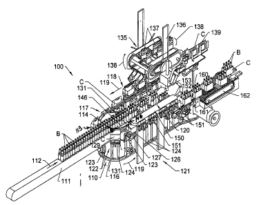
[00441 FIGS. 8 -11 illustrate a second embodiment of the packaging system 100
according to the principles of the present invention. As discussed above with
respect
to the embodiment of FIGS. 2 - 7, the packaging system 100 (FIGS. 8 and 11) of
the
14
CA 02650249 2008-10-23
WO 2007/136512 PCT/US2007/010371
present embodiment will include a loading carousel 110 for loading articles or
products, such as bottles B or other similar products, into cartons C, here
illustrated as
basket-type cartons or containers, each having a series of compartments
defined
therein. As illustrated in FIGS. 8 and 9, the articles to be packaged, such as
bottles
B, are conveyed in one or more lanes or lines of articles along an article
infeed path
into the packaging system 100 along an article infeed conveyor 111 in the
direction of
arrow 112. In this embodiment, the article infeed conveyor 111 typically
enters the
packing system 100 at the upstream end 113 of the packaging system, generally
at an
elevated position with respect to the loading carousel 110 and terminating at
a
discharge point 114.
[00451 The loading carousel 110 includes a substantially elliptically shaped
frame
116 having a first side 117 along which the open carton C are engaged and
picked up
at an initial or pickup point 118 (FIG. 8). The cartons thereafter are
conveyed about
the loading carousel along a loading path in the direction of arrow 119 under
the
article infeed conveyor 111, to a loading point 120 along a second side 121 of
the
loading carousel. The loading carousel 110 further includes a series of
carriers 122
for conveying cartons about their loading path indicated by arrow 119. As
illustrated
in FIGS. 8 - 10, each of the carriers 122 generally includes a base 123 that
is
slideably mounted on a pair of vertically extending support rods 124 that are
attached
to the frame 116 of the loading carousel so as to be rotated therewith to move
the
carriers about the loading path 119.
[00461 Container or carton supports 126 (FIGS. 9 - 10) are mounted on the base
of
each carrier 122, and are typically vertically spaced from their base 123 by
upstanding
CA 02650249 2008-10-23
WO 2007/136512 PCT/US2007/010371
plates or brackets 127. Each of the container supports generally is a U- or C-
shaped
member having front and rear walls 128 and 129, respectively, with a
longitudinally
extending section or portion 131 therebetween. The container supports 126
further are
spaced apart, as indicated in FIGS. 10, so as to define a space or passage 132
therebetween. The cartons C are received from a carton opener 135 (FIGS. 8, 9)
positioned along the first side 117 of the loading carousel, upstream from the
carton
pickup point 118, as the carriers are moved along an initial or upstream
portion of the
carton loading path 119. The carriers receive the opened cartons with the
front and
rear corners of the cartons engaging the corners between the front and rear
walls and
intermediate sections of each of the container supports, and with the outer
side edges
of the cartons being supported by the intermediate sections 131 (FIG. 9) of
each of the
container supports 126.
[00471 The carton opener 135 generally will have a substantially similar
construction to the carton opener as described above with respect to the
embodiment
of FIGS. 2 - 7, generally including a frame 136 (FIG. 8), about which a series
of
carton opening assemblies 137 are conveyed in the direction of arrows 138. The
carton opening assemblies 137 will engage and pick flat folded cartons C from
a
magazine 139, or similar supply of cartons, progressively opening the cartons
before
releasing the cartons C onto the container supports 126 of each of the
carriers 122 at
the pickup point 118 as indicated in FIGS. 8 and 10.
[00481 As generally illustrated in FIG. 9, a cam track 141 is mounted within
the
frame 116 of the loading carousel 110, extending along a substantially
elliptical path
within the confines of the loading carousel frame. A cam follower or roller
142 is
16
CA 02650249 2008-10-23
WO 2007/136512 PCT/US2007/010371
attached to a rear side surface of the base 123 of each of the carriers 122
and engages
and rolls along the cam track as the carriers are transported around the
loading
carousel 110 in the direction of arrows 119. As a result, as the cam followers
roll
along the cam track 141, the carriers are moved upwardly and downwardly in the
direction of arrows 143 and 143' as indicated in FIG. 9. Such movement causes
the
carriers, and thus the cartons carried thereby, to be raised and lowered as
the carriers
are transported about the loading carousel 110 along the initial or upstream,
intermediate, and downstream portions of the loading path 119 of the cartons.
As
indicated in FIG. 8, the carriers accordingly are transported from a raised
configuration at the pickup point 118 wherein the opened cartons C are loaded
into
each of the carriers 122, and are lowered as the cartons are conveyed along
the
intermediate portion of the loading path 119, so as to pass beneath the
article infeed
conveyor 111. Thereafter, the cartons will be raised to an elevated position
as they
move along the downstream portion of their loading path, coming up from
beneath the
bottles B at the loading point 120 for loading the bottles into the cartons,
as indicated
in FIGS. 8 and 11.
[0049] As generally illustrated in FIGS. 9 and 10, a dead plate 146 can be
mounted
at the discharge end 114 of the article infeed conveyor 111, extending
longitudinally
therefrom between the discharge end of the article infeed conveyor 111 and the
loading point 120 of the carriers 122. The dead plate typically will be a
substantially
flat, longitudinally extending plate having a smooth upper surface 147 along
which
the bottles are received and moved for loading into their respective cartons.
17
CA 02650249 2008-10-23
WO 2007/136512 PCT/US2007/010371
[00501 A selector station 150 (FIGS. 8 and 9) is mounted along the dead plate
146
for engaging and grouping the bottles into selected groups G, such as in six-
pack
configurations as illustrated in FIGS. 8 and 9, or in other configurations or
arrangements as needed or desired. The selector station 150 can include a
series of
selectors such as selector wedges or blocks 151 arranged in groups or series,
such as
in groups of I - 3 selector wedges moving along both sides of the dead plate.
The
selector wedges 151 generally will be mounted on and conveyed into engagement
with
the bottles B by conveyors 152 and 153 extending on each side of the dead
plate and
article infeed path. Each of the selector wedges 151 (FIG. 11) typically can
include a
substantially arcuate-shaped upper portion or base 154, defining a recess in
which one
of the bottles will be received, and a downwardly extending guide or finger
portion
156. The guides 156 are each adapted to engage and be received within a
compartment of a carton C as the cartons are raised toward bottles at the
loading point
144.
[00511 As indicated in FIGS. 8 - 10, the selector wedges generally will engage
a
series of products, i.e., I - 3 bottles, so as to create a product group G,
such as a six-
pack of bottles, that are separated and moved forwardly along the dead plate
and away
from the article infeed conveyor, toward the loading point 120. At the loading
point,
the bottles will be lowered or dropped into the compartments of their
respective
cartons C as the cartons are raised toward the bottles by the upward movement
of the
cam followers 142 of the carriers 122 along their cam track 141, as indicated
in FIGS.
9 and 11. The fingers or guide portions 156 of each of the selector wedges 151
are
received within the compartments of the cartons and tend to guide the bottles
into
18
CA 02650249 2008-10-23
WO 2007/136512 PCT/US2007/010371
their respective compartments of the cartons to control the feeding of the
bottles
therein to reduce or minimize mis-feeding and/or the shock or jarring forces
translated
to the carriers and support rods from the bottles dropping into the cartons.
[00521 As illustrated in FIG. 9, after the bottles have been received within
the
compartments of their associated cartons, the cartons thereafter are
progressively
lowered as the cam followers 142 of the carriers 122 continue along the cam
track 141
in the direction of arrows 143. As the carriers are moved forwardly
downwardly, the
cartons are deposited onto a takeoff conveyor 160 (FIGS. 8- and 9). The
takeoff
conveyor generally comprises a narrow conveyor belt 161 of a size adapted to
be
received within the passage 132 defined between the container supports 126 of
each of
the carriers. As indicated in FIG. 9, the carriers deposit their cartons C
onto the
conveyor belt 161 of the takeoff conveyor 160, as the carriers are moved
forwardly
and are lowered by the continued downward movement of their cam followers 142
along the cam track 141. The carriers are lowered to an elevation below the
elevation
of the takeoff conveyor 160, so that the carriers can be turned and pass
therebeneath
without interference with the takeoff conveyor 160 or the cartons contained
thereon.
[00531 Thereafter, as indicated in FIG. 8, the loaded cartons C are
transferred to a
discharge conveyor 162, with the loaded cartons typically being divided into
two or
more lines or paths. The discharge conveyor 162 will thereafter discharge the
loaded
cartons away from the packaging system 100.to a downstream station such as a
case
packer or other station for collecting and packaging the loaded packages or
cartons for
storage and/or transport.
19
CA 02650249 2008-10-23
WO 2007/136512 PCT/US2007/010371
[00541 The loading carousels illustrated in the Figures have a two-sided
configuration generally utilizing two spaced, rotating supports. An
alternative loading
carousel can have, for example, three sides formed by three rotating supports.
The
functions of pickup and loading can be performed, for example, along two or
more of
the three sides of the carousel. Another alternative loading carousel could be
rectangular in shape, with the functions of pickup and loading of the cartons
performed along two or more of the four sides of the carousel. In addition,
although
two sides of the packaging system of the present invention could be tended by
an
operator, the packaging system can account for any missed cartons in the
loading
function on the first side of the loading carousel by a single operator
positioned along
the second side of the packaging system.
[00551 The present invention further is suitable for loading a variety of
articles in a
variety of containers. Suitable articles include, for example, bottles as
shown in the
drawings, cans or similar articles. Suitable containers can include, for
example,
paperboard cartons and basket type containers or carriers. The containers used
with
the packaging system can include, for example, a glued base, locking tabs,
and/or
other types of carton closures. The packaging system further can utilize
existing style
basket containers or can operate with alternative base hole patterns for
engagement by
a transport conveyor. The base crease hole pattern of the cartons C can be
configured
or created with an existing Graphic Packaging International, Inc. "A-B Ruff-
Rider"
die, or a similar die, with base crease holes added. Two pairs of base crease
holes can
be added, one for use by the container infeed and one for use by the carousel.
The two
pairs of base crease holes provide a larger transfer target and eliminate
lug/finger
CA 02650249 2008-10-23
WO 2007/136512 PCT/US2007/010371
interference, as well as allow the possibility of repitching the input or
carton transport
conveyor to between a 12.5" paper feed and a 10" pitch carousel for higher
packaging
per minute at lower linear speeds. The packaging system further generally can
allow
for a surge requirement of up to at least 250 packages formed per minute.
[00561 It will be understood by those skilled in the art that while the
invention has
been discussed above with reference to preferred embodiments, various changes,
modifications and additions can be made thereto without departing from the
spirit and
scope of the invention as set forth in the following claims.
21