Note: Descriptions are shown in the official language in which they were submitted.
CA 02650265 2011-02-07
COOKING PACKAGE
[0001] The present invention relates to the field of food preparation, and in
particular, relates to materials and constructs that may be used to prepare
foods in a
microwave oven.
[0002] Background of the Invention
[0003] Microwave ovens commonly are used to cook food in a rapid and effective
manner. To optimize the cooking performance of microwave ovens, various food
packaging arrangements have been developed to block, enhance, direct, and
otherwise affect microwave interaction with food.
[0004] If browning or crisping of the exterior of the food item is desired,
the food
item is placed in a container that includes a susceptor. The susceptor
typically
includes a microwave energy interactive material, such as a metal, that
absorbs,
reflects, and transmits microwave energy in varying proportions. The surface
to be
browned is placed proximate the susceptor. The susceptor absorbs the microwave
energy and thereby becomes hot, and transmits heat to the food item to promote
surface browning and crisping. Further, some of the microwave energy is
typically
transmitted to the inside of the food item.
[0005] Numerous susceptor configurations, shapes, and sizes are known in the
art.
Depending on the susceptor arrangement, the time of exposure to microwave
energy,
the desired degree of browning and crisping, and other factors, the susceptor
may be
in intimate or proximate contact with the food item. Thus, a material or
package
1
CA 02650265 2011-02-07
including a susceptor may be used to cook a food item, and to brown or crisp
the
surface of the food item in a way similar to conventional frying, baking, or
grilling.
[0006] One particular food packaging arrangement that may employ susceptors
involves closed cells formed between layers of packaging material. Upon
exposure to
microwave energy, the cells expand to form inflated cells that thermally
insulate the
food item in the package from the environment exterior to the package. One
example
of a microwave packaging material that provides inflatable cells is described
in co-
pending published PCT application PCT/US03/03779 titled "Insulating Microwave
Interactive Packaging".
[0007] Despite prior advances, numerous challenges in microwave cooking
remain.
For example, many existing packages are fixed in shape and do not provide
cooking
surfaces that are positioned sufficiently close to the food item to brown or
crisp the
surface of the food item. Thus, there remains a need for improved microwave
energy
interactive packages.
Summary of the Invention
[0008] In general, one aspect of the invention is generally directed to a
package for
heating a food product in a microwave oven. The package comprises a tray for
holding the food product and a flexible cover for at least partially covering
the tray
and the food product. The cover comprises a microwave interactive material.
[0009] In another aspect, the invention is generally directed to a package for
a food
product having a shape. The package comprises a tray for holding the food
product
and a flexible cover at least partially covering the tray and the food
product. The
flexible cover comprises a plurality of fold lines that are substantially
parallel to one
another so that the flexible cover is adapted for at least partially
conforming to the
shape of the food product.
[00010] In another aspect, the invention is generally directed to a blank for
forming a
package for holding and heating a food product. The blank comprises a
plurality of
tray panels comprising a central panel and a plurality of side panels foldably
attached
2
CA 02650265 2008-10-23
WO 2007/136839 PCT/US2007/012091
to the central panel for being positioned relative to the central panel to
form a tray
when the blank is formed into the package. A flexible flap is foldably
attached to at
least one of the central panel and the plurality of panels. The flexible flap
has a
plurality of fold lines that are substantially parallel to one another so that
the flexible
flap has a plurality of independently moveable sections respectively at least
partially
defined by fold lines of the plurality of fold lines. The plurality of fold
lines includes
at least three fold lines, and the plurality of independently moveable
sections includes
at least three independently moveable sections.
[00011] In another aspect, the invention is generally directed to a
combination of a
tray blank, for forming a tray, and a cover blank, for forming a cover for at
least
partially covering the tray. The tray blank comprising a central panel and a
plurality
of side panels foldably attached to the central panel. The cover blank
comprises
spaced apart lateral fold lines and independently moveable sections of the
blank that
are at least partially defined by the lateral fold lines.
[00012] In another aspect, the invention is generally directed to a method of
preparing
a food product. The method comprises providing a package comprising a tray and
a
flexible cover. A food product is placed in the tray and at least partially
covered with
the cover. The at least partially covering the food product includes bending
the cover
so that the cover at least partially conforms to the shape of the food
product. The
method further comprises heating the food product in a microwave oven.
[00013] In another aspect, the invention is generally directed to a package
for heating a
food product in a microwave oven. The package comprises a tray and a flexible
cover
for at least partially covering the tray. The cover comprises a microwave
interactive
material.
[00014] In another aspect, the invention is generally directed to a blank for
forming a
package for holding and heating a food product. The blank comprises a
plurality of
tray panels for forming a tray when the blank is formed into the package. A
flexible
flap is foldably attached to at least one of the tray panels and has a
plurality of fold
lines. The flexible flap has a plurality of independently moveable sections
respectively at least partially defined by fold lines of the plurality of fold
lines.
3
CA 02650265 2011-02-07
[00014.1] According to one aspect of the present invention there is provided a
package
for heating a food product in a microwave oven, the package comprising a tray
for holding the food product and being formed from a blank of rigid material,
the tray comprising a central panel for supporting the food product and two
side panels foldably connected to the central panel and positioned relative to
the central panel to form the tray, the central panel having a width between
the
two side panels; and a flexible cover for at least partially covering the tray
and
the food product and for at least partially conforming to a shape of the food
product in the tray, wherein the flexible cover is formed from the blank of
rigid material and comprises a flap foldably attached to one of the side
panels
at a fold line, and a microwave interactive material attached to the flap, the
flap is adapted to wrap around the food product and form an open ended
cooking sleeve, the flap has spaced apart lateral fold lines forming
independently moveable sections of the flap for wrapping around the food
product, the flap has a length from the fold line to a free edge of the flap
opposite the fold line, the length of the flap being greater than the width of
the
central panel.
[00014.2] According to a further aspect of the present invention there is
provided a
package for a food product having a shape, the package comprising a tray for
holding the food product and being formed from a blank of rigid material, the
tray comprising a central panel for supporting the food product and two side
panels foldably connected to the central panel and positioned relative to the
central panel to form the tray, the central panel having a width between the
two side panels; and a flexible cover at least partially covering the tray and
the
food product, wherein the flexible cover is formed from the blank of rigid
material and comprises a flap foldably attached to one of the side panels at a
fold line, the flap has a plurality of fold lines that are substantially
parallel to
one another so that the flexible cover is adapted for at least partially
conforming to the shape of the food product and form an open ended sleeve,
the plurality of fold lines comprise spaced apart lateral fold lines forming
independently moveable sections of the flap for wrapping around the food
product, the flap has a length from the fold line to a free edge of the flap
3a
CA 02650265 2011-02-07
opposite the fold line, the length of the flap being greater than the width of
the
central panel.
[00014.3] According to another aspect of the present invention there is
provided a
blank of rigid material for forming a package for holding and heating a food
product, the blank comprising a plurality of tray panels comprising a central
panel for supporting a food product and two side panels foldably attached to
the central panel for being positioned relative to the central panel to form a
tray when the blank is formed into the package, and a flexible flap foldably
attached to one of the side panels at a fold line, the flexible flap having a
plurality of fold lines that are substantially parallel to one another so that
the
flexible flap has a plurality of independently moveable sections respectively
at
least partially defined by fold lines of the plurality of fold lines wherein
the
plurality of fold lines includes at least three fold lines, and the plurality
of
independently moveable sections includes at least three independently
moveable sections, the flexible flap being for at least partially conforming
to a
shape of the food product in the tray and forming an open ended sleeve, when
the blank is formed into the package, the plurality of fold lines comprise
spaced apart lateral fold lines forming the independently moveable sections of
the flap that are for wrapping around the food product, the flap has a length
from the fold line to a free edge of the flap opposite the fold line, the
length of
the flap being greater than the width of the central panel.
[00014.4] According to a still further aspect of the present invention there
is provided a
method of preparing a food product comprising: providing a package
comprising a tray and a flexible cover, the tray being formed from a blank of
rigid material, the tray comprising a central panel for supporting the food
product and two side panels foldably connected to the central panel and
positioned relative to the central panel to form the tray, the central panel
having a width between the two side panels, the flexible cover is formed from
the blank of rigid material and comprises a flap foldably attached to one of
the
side panels at a fold line, the flap has a plurality of fold lines that are
substantially parallel to one another so that the flexible cover is adapted
for at
least partially conforming to the shape of the food product in the tray and
form
3b
CA 02650265 2011-02-07
an open ended sleeve, the plurality of fold lines comprise spaced apart
lateral
fold lines forming independently moveable sections of the flap for wrapping
around the food product, the flap has a length from the fold line to a free
edge
of the flap opposite the fold line, the length of the flap being greater than
the
width of the central panel; placing a food product in the tray; at least
partially
covering the food product with the cover including folding the cover relative
to the tray and bending the cover so that the cover at least partially
conforms
to the shape of the food product in the tray and forms an open ended sleeve
that wraps around the food product; and heating the food product in a
microwave oven.
3c
CA 02650265 2008-10-23
WO 2007/136839 PCT/US2007/012091
[00015] Those skilled in the art will appreciate the above stated advantages
and other
advantages and benefits of various additional embodiments reading the
following
detailed description of the embodiments with reference to the below-listed
drawing
figures.
[00016] According to common practice, the various features of the drawings
discussed
below are not necessarily drawn to scale. Dimensions of various features and
elements in the drawings may be expanded or reduced to more clearly illustrate
the
embodiments of the invention.
Brief Description of the Drawings
[00017] Fig. 1 is a plan view of a blank used to form a package according to a
first
embodiment of the present invention.
[00018] Fig. 2 is a perspective of the package in a partially assembled
configuration.
[00019] Fig. 3 is a perspective of the package further assembled.
[00020] Fig. 4 is a perspective of the package assembled for heating a food
product in
accordance with one example of the first embodiment.
[00021] Fig. 5 is a schematic cross-sectional view of an insulating microwave
material
that may be used in accordance with the present invention.
[000221 Fig. 6 is a schematic perspective view of the insulating microwave
material of
Fig. 5.
[00023] Fig. 7 is a schematic perspective view of the insulating microwave
material of
Fig. 5 after exposure to microwave energy.
[00024] Fig. 8 is a schematic cross-sectional view of an alternative
insulating
microwave material that may be used in accordance with the present invention.
[000251 Fig. 9 is a plan view of a blank used to form a package of a second
embodiment of the present invention.
[00026] Fig. 9A is a perspective of the package of the second embodiment.
[00027] Fig. 10 is a plan view of a tray blank used to form a package of a
third
embodiment of the present invention.
[00028] Fig. 11 is a plan view of a lid blank used to form a package of the
third
embodiment.
4
CA 02650265 2008-10-23
WO 2007/136839 PCT/US2007/012091
[00029] Fig. 11A is a perspective of the package of the third embodiment.
[00030] Fig. 12 is a plan view of a blank used to form a package of a fourth
embodiment of the present invention.
[00031] Fig. 12A is a perspective of the package of the fourth embodiment.
[00032] Corresponding parts are designated by corresponding reference numbers
throughout the drawings.
Detailed Description of the Exemplary Embodiments
[00033] The present invention relates generally to various aspects of
materials and
packages for cooking food items, and methods of making such materials and
packages. Although several different inventions, aspects, implementations, and
embodiments of the various inventions are provided, numerous
interrelationships
between, combinations thereof, and modifications of the various inventions,
aspects,
implementations, and embodiments of the inventions are contemplated hereby.
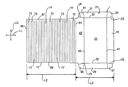
[00034] Fig. 1 is a plan view of a blank, generally indicated at 1, used to
form a
package 3 (Figs. 2-4) of a first embodiment of the invention. The package 3 is
used to
hold a food product P (Fig. 9A), such as a sandwich, calzone, turnover,
burrito, or any
other food product, during cooking of the food product. In one example, the
package
3 with food product P is placed in a microwave oven (not shown) to heat and/or
cook
the food product. In the illustrated embodiment, the package 3 includes a tray
7 that is
sized to hold the food product and a flexible flap 11 (broadly "flexible
cover")
foldably attached to the tray that at least partially wraps around the food
product. The
flexible flap 1 1 and/or a portion of the tray 7 may have an element for use
in cooking,
heating, browning, and/or shielding (e.g., a microwave energy interactive
element 15
such as, but not limited to, a susceptor) mounted thereto. It is understood
that the
microwave energy interactive element 15 (Fig. 2) may be omitted from the
package 3.
[00035] The blank 1 has a longitudinal axis LI and a lateral axis L2. The
blank 1
includes a bottom panel 21 that forms the tray 7 of the package. The bottom
panel 21
includes a central panel 23, and first and second panels 27, 29 at respective
lateral
ends of the central panel. The side panels 27, 29 are respectively foldably
connected
to the central panel 23 at respective longitudinal fold lines 33, 35. Third
and fourth
CA 02650265 2008-10-23
WO 2007/136839 PCT/US2007/012091
side panels 41, 43 are foldably connected to the central panel 23 at
respective
longitudinal ends of the central panel. The side panels 41, 43 are foldably
connected
to the central panel 23 at respective lateral fold lines 47, 49. In the
illustrated
embodiment, the bottom panel 21 includes two corner panels 51, 53 foldably
attached
to the first side panel 27 along respective lateral fold lines 49, 47, and two
corner
panels 55, 57 foldably attached to the second side panel 29 along the
respective lateral
fold lines 49, 47. The corner panels 51, 53 55, 57 are respectively separated
from the
side panels 41, 43 by slits 58 or the like. The side panels 27, 29, 41, 43 and
corner
panels 51, 53, 55, 57 are each foldable relative to the central panel 23 so
that the
bottom panel 21 forms the 7 tray that contains the food product in the package
3
assembled from the blank 1. Differently configured bottom panels 21 and trays
7 are
also within the scope of the present invention.
[00036] In the illustrated embodiment, the flexible flap I1 is foldably
connected to the
side panel 43 at a first lateral fold line 61. The flexible flap 11 extends
from the side
panel 43 and has a longitudinal edge 65 and two spaced apart lateral edges 67,
69. As
shown in Fig. 1, the flexible flap 11 is generally rectangular and has twenty-
nine
spaced apart fold lines 73 that extend in the lateral direction across the
flap. Only a
representative few of the fold lines 72 are identified by their reference
numbers in Fig.
1. The fold lines 73 may be cut lines, scores, or any other lines of weakening
in the
flap 11. In the illustrated embodiment, the fold -lines 73 are spaced evenly
across the
length of the flap 11 between the fold line 61 and the longitudinal edge 65.
The
flexible flap 11 has independently moveable sections 74 between the fold lines
73. In
one embodiment, the adjacent fold lines 73 are spaced apart approximately '04
inch (6
mm) but it is understood that the fold lines may have other spacing. The
flexible flap
11 has a width approximately equal to the width of the central panel 23;
however, the
flap may be otherwise shaped and dimensioned without departing from the scope
of
this invention.
[00037] In the illustrated embodiment, the flexible flap 11 is made of the
same
generally rigid material (e.g., paperboard) as the tray 7 and is made flexible
by the fold
lines 73. The independently moveable sections 74 between the fold lines 73
allow the
flap 11 to flex and conform to the shape of the food product P. It is
understood that
6
CA 02650265 2008-10-23
WO 2007/136839 PCT/US2007/012091
the flexible flap 11 could comprise other materials (e.g., thin films or webs)
that may
be flexible without fold lines 73.
[00038] In the embodiment of Fig. 1, the bottom panel 21 has a width L3 in the
longitudinal direction L1 of the blank 1 and the flexible flap 11 has a length
L4 in the
longitudinal direction of the blank. In the illustrated embodiment, the length
L4 of the
flexible flap 1 l is greater than the width L3 of the bottom panel 21. In one
particular
embodiment the length L4 is approximately 7-1/2 inches (190 mm) and the width
L3
is approximately 5-1/2 inches (140 mm). All dimensional information presented
herein is intended to be illustrative of exemplary embodiments and is not
intended to
limit the scope of the invention.
[00039] In the illustrated embodiment, the microwave interactive element 15
(Fig. 2)
covers, at least in part, the interior surfaces of the flexible flap 11, the
second
longitudinal end panel 43, and the central panel 23. In one embodiment, the
microwave interactive element 15 is a generally rectangular panel that is
attached to
the blank I by adhesive material (not shown) or by an other acceptable
mechanism
that is proximate the edges of the panel. It is understood that the adhesive
attaching
the microwave interactive 15 to the blank 1 may be a patterned layer of
adhesive such
as evenly spaced spots of adhesive or the adhesive could be otherwise applied
without
departing from the scope of this invention. The perimeter bonding of the
microwave
interactive element 15 to the blank 1 may allow the material of the microwave
interactive element to more easily expand when heated to more effectively
brown or
crisp the food product in the package 3.
[000401 The material of the microwave interactive element 15 can be, or
include, any
type of known microwave interactive material, such as a susceptor that is for
absorbing microwaves and/or converting microwaves into thermal energy to
thereby
become hot and to at least radiantly provide heat to food, a microwave energy
shielding element that is for reflecting microwaves away from at least a
portion of a
food item, a microwave energy directing element for directing microwaves
toward at
least a portion of a food item, and various combinations of these and other
features.
In accordance with exemplary embodiments of the present invention, the
material of
the microwave interactive element 15 can more specifically be a microwave
insulating
7
CA 02650265 2011-02-07
material (discussed in detail below) in contact with the food product for
heating,
browning, and/or crisping the food product during operation of the microwave
oven. It
is understood that the food product may be a type of food product that may or
may not
require browning or crisping during microwave heating without departing from
the
scope of this invention.
[00041] According to various aspects of the present invention, the material of
the
microwave interactive element 15 of the present invention could be any
arrangement of
layers, such as polymer (e.g., polyester) film layers, susceptor or "microwave
interactive" layers, paper layers, continuous and discontinuous adhesive
layers, and
patterned adhesive layers, that provides an insulating effect. The material of
the
microwave interactive element 15 may include one or more susceptors, one or
more
expandable insulating cells, or a combination of susceptors and expandable
insulating
cells. Examples of materials that may be suitable, alone or in combination,
include, but
are not limited to, QWIKWAVE brand susceptor, QWIKWAVE FOCUS brand
susceptor, MICRO-RITE brand susceptor, MICROFLEX Q brand susceptor, and
QUILTWAVE brand susceptor, each of which is commercially available from
Graphic
Packaging International, Inc. The material may be any suitable expandable cell
material
as desired, and, in some instances, may include any of the materials described
herein,
any of the materials described in PCT Application PCT/US03/03779.
Alternatively and
as should be apparent from the foregoing, as one example the microwave
interactive
element 15 can consist essentially solely of a susceptor.
[00042] An exemplary material of the microwave interactive element 15 is
depicted in
Figs. 5-8. In each of the examples shown herein, it should be understood that
the layer
widths are not necessarily shown in perspective. In some instances, for
example, the
adhesive layers are very thin with respect to other layers, but are
nonetheless shown
with some thickness for purposes of clearly illustrating the arrangement of
layers.
8
CA 02650265 2008-10-23
WO 2007/136839 PCT/US2007/012091
[000431 Referring to Fig. 5, the material of the microwave interactive element
15 may
be a combination of several different material layers. A susceptor 12, which
typically
includes a thin layer of microwave interactive material 14 on a first plastic
film 16, is
bonded, for example by lamination with an adhesive (not shown), to a
dimensionally
stable substrate 20, for example, paper. The substrate 20 is bonded to a
second plastic
film 22 using a patterned adhesive 26 or other material,'such that closed
cells 28 are
typically formed in the material of the microwave interactive element 15. The
closed
cells 28 are substantially resistant to vapor migration.
[000441 Optionally, an additional substrate layer 24 may be adhered by
adhesive or
otherwise to the first plastic film 16 opposite the microwave interactive
element
material, as depicted in Fig. 8. The additional substrate layer 24 may be a
layer of
paper or any other suitable material, and may be provided to shield the food
item (not
shown) from any flakes of susceptor film that craze and peel away from the
substrate
during heating. The material for the microwave interactive element 15 is a
substantially flat, multi-layered sheet, as shown in Fig. 6.
[000451 Fig. 7 depicts the exemplary material of the microwave interactive
element 15
of Figs. 5 and 6 subjected to microwave energy from a microwave oven (not
shown).
As the susceptor 12 heats upon impingement by microwave energy, water vapor
and
other gases normally held in the substrate 20, and any air trapped in the thin
space
between the second plastic film 22 and the substrate 20 in the closed cells
28, expand.
The expansion of water vapor and air (or any other suitable material) in the
closed
cells 28 applies pressure on the susceptor 12 and the substrate 20 on one side
and the
second plastic film 22 on the other side of the closed cells 28. Each side of
the
material 15 forming the closed cells 28 reacts simultaneously, but uniquely,
to the
heating and vapor expansion. The cells 28 expand or inflate to form a quilted
top
surface 32 of "pillows" separated by channels (not shown) in' the susceptor 12
and
substrate 20 lamination, which lofts above a bottom surface 34 formed by the
second
plastic film 22. This expansion may occur within I to 15 seconds in an
energized
microwave oven, and in some instances, may occur within 2 to 10 seconds.
9
CA 02650265 2008-10-23
WO 2007/136839 PCT/US2007/012091
[00046] The expansion of the cells 28 allows the microwave insulating material
15 to
conform more closely to the surface of the food item, placing the susceptor 12
in
greater proximity to the food item. This enhances the ability of the microwave
insulating material 15 to brown and crisp the surface of the food item by
conduction
heating, in addition to some convection heating, of the food item. It is
understood that
the microwave insulating material 15 used in the package 3 of the present
invention
may include other materials than described herein and may be otherwise
arranged,
configured, and designed, without departing from the scope of this invention.
Further,
multiple layers of microwave insulating material 15 may be used in the package
3.
[00047] As shown in Figs. 2-4 and described in the following in accordance
with one
acceptable example, the package 3 is formed from the blank by first upwardly
folding
the side panels 27, 29, 41, 43 and folding the corner panels 51, 53, 55, 57 of
the
bottom panel 21 relative to the central panel 23 to form the tray 7 having
upwardly
extending side walls that contain the food product P. Each of the corner
panels 51,
53, 55, 57 may be folded perpendicular to a respective side panel 27, 29 and
placed in
a generally face-to-face relationship with a respective side panel 41, 43. The
corner
panels 51, 53, 55, 57 may be attached to one of the respective side panels 41,
43 by
adhesive. Next, the flexible flap 11 is folded upward along the lateral fold
line 61 to
the position shown in Fig. 2. As shown in Fig. 3, the flexible flap 11 is
formed into a
generally C-shaped wrap for placement around a food product. The C-shaped
flexible
flap 11 is placed around the food product P and folded downward to the
position of
Fig. 4. The flexible flap 11 wraps around the food product P and includes a
generally
flat upper layer 81 extending from the side panel 43 of the bottom panel 21, a
curved
portion 83, and a generally flat bottom layer 85 that wraps around the bottom
of the
food product. It is understood that the food product P may be placed in the C-
shaped
flexible flap 11 as the flap is being folded downward to cover the tray 7 or
the food
product may be first placed on the central panel 23 of the tray with the
flexible flap
being shaped around and covering the food product. It is understood that the
flexible
flap 11 of the illustrated embodiment is positioned around the food product P
to form
an open ended cooking sleeve that includes the microwave insulating material
15
wrapped around and covering the food product. The plurality of lateral fold
lines 73
CA 02650265 2008-10-23
WO 2007/136839 PCT/US2007/012091
give the flexible flap 11 the required flexibility to allow the flap, and the
microwave
insulating material attached thereto, to conform closely to the surface of the
food
product which may be irregular in shape.
[00048] Prior to cooking, some of the microwave insulating material 15 may not
be in
intimate contact with an irregularly shaped food product wrapped in the
flexible flap
11. As such, only some portions of the food product will be in direct contact
with the
susceptor material 12. As noted above for one version of the first embodiment,
the
expansion of the cells 28 of the microwave insulting material 15 causes the
susceptor
12 to bulge against the food product, providing increased contact with the
surface of
the food product, and thus more efficient heating, browning, and/or crisping
thereof.
[00049] Fig. 9 shows a second embodiment of the present invention in the form
of a
blank 101 used to form a package 103 (Fig. 9A) for heating food products P in
a
similar manner as the first embodiment. The package 103 is similar to the
package 3
of the first embodiment except that the blank 101 includes a first microwave
energy
interactive element 105 attached to the flexible flap 107 (broadly "cover")
and a
second microwave energy interactive element 109 attached to the central panel
111.
Also, the flexible flap 107 is shorter than the flap l 1 of the first
embodiment so that
the flexible flap 107 covers the tray 108 of the second embodiment without
wrapping
the food product P.
[00050] The tray 108 is formed from a bottom panel 113 of the blank 101 that
is
similar to the bottom panel 21 of the first embodiment in that it has a
central panel
111 and four side panels 121, 122, 123, 124. The bottom panel 113 has
ventilation
holes 117 in the side panels 121, 123. The flexible flap 107 is attached to
the side
panel 123 at lateral fold line 125 and has four spaced apart lateral fold
lines 127
extending between the lateral edges of the flap. The first microwave
interactive
element 105 is attached to the flexible flap 107 by adhesive 129
(schematically
shown) at four locations generally adjacent a respective corner of the first
microwave
interactive element. The second microwave interactive element 109 is attached
to the
central panel 111 of the bottom panel 113 by adhesive 133 (schematically
shown) at
four locations generally adjacent a respective corner of the second microwave
interactive element. As shown in Fig. 9, the first microwave interactive
element 105
11
CA 02650265 2008-10-23
WO 2007/136839 PCT/US2007/012091
and second microwave interactive element 109 are both rectangular, but the
elements
may be otherwise shaped (e.g., square, irregular-shaped, etc.) without
departing from
the scope of this invention. The microwave interactive elements 105, 109 of
this
embodiment may comprise a microwave interactive material similar to or the
same as
the material described above for the first embodiment, or the microwave
interactive
elements may be otherwise configured without departing from the scope of this
invention. Further, the microwave interactive elements 105, 109 may comprise
multiple layers of microwave insulating material.
[00051] In using the package 103 of the second embodiment in accordance with
one
acceptable method described in the following, the tray 108 is first formed
from the
bottom panel 113 and the food product P is.placed in the tray in contact with
the
second microwave insulating panel 109. The food product P is enclosed by
covering
the tray 108 formed from the bottom panel 113 with the flexible flap 107 by
folding
the flexible flap along lateral fold line 125. The flexible flap 107 may be
secured to
the side panel 121 of the bottom panel 113 by various attachment means. For
example in the illustrated embodiment, the flexible flap 107 has a locking tab
142
formed by a cut line 144 that is sized for being received in a locking recess
146 in the
side panel 121 of the tray to retain the flexible flap in the closed position
of Fig. 9A.
The tab 142 can be outwardly folded from the position shown in Fig. 9A and
inserted
into the locking recess 146 to hold the flexible flap 107 in the closed
position. When
the flexible flap 107 is closed as shown in Fig. 9A, the first microwave
interactive
element 105 is positioned in contact with or in a close proximate relationship
with the
top surface of the food product P. As with the previous embodiment, the first
and
second microwave interactive elements 105, 109 of the package browns and
crisps the
food product P when the package 103 is heated in a microwave oven.
[00052] In the embodiment of Fig. 9, the bottom panel 113 has a width L5 in
the
longitudinal direction of the blank 101 and the flexible flap 107 has a width
L6 in the
longitudinal direction of the blank. In the illustrated embodiment, the width
L6 of the
flexible flap 107 is approximately equal to the width L5 of the bottom panel
113. In
one particular embodiment the width L5 and the width L6 are approximately 5-
1/4
inches (133 mm). All dimensional information presented herein is intended to
be
12
CA 02650265 2008-10-23
WO 2007/136839 PCT/US2007/012091
illustrative of exemplary embodiments and is not intended to limit the scope
of the
invention.
[00053] Figs. 10-11A show a third embodiment of a package 202 (Fig. IIA) of
the
present invention. The package 202 is similar to the previous embodiment
except that
the tray 206 is formed from a tray blank 201 (Fig. 10) and the cover 208 is
formed
from a cover blank 203 (Fig. 11). The tray and cover blanks 201, 203 cooperate
to
form the package 202 for heating the food product in a similar manner as the
previous
embodiments.
[00054] As best understood with reference to Fig. 11, the cover blank 203
includes a
generally rectangular panel 205 with the first microwave insulating panel 207
attached
thereto by adhesive 211 (schematically shown) located generally adjacent the
respective corners of the panel. The cover blank 203 includes two spaced apart
fold
lines 215 extending between the lateral edges of the panel and three
independently
moveable sections 216 defined by the fold lines.
[00055] As best understood with reference to Fig. 10, the tray blank 201
includes a
generally rectangular central panel 217 with the second microwave insulating
panel
221 attached thereto by adhesive 225 (schematically shown) located generally
adjacent the respective corners of the central panel. As with the previous
embodiments, the tray blank 201 includes side panels 227, 229, 241, 243 and
corner
panels 251, 253, 255, 257 for positioning relative to the central panel 217
when
forming the tray 206.
[00056] It is understood that the package 202 of this embodiment may be
assembled by
first forming the food-holding tray 206 from the tray blank 201 in a similar
manner as
the previous embodiments. Food product P is placed on'the central panel 217 of
the
tray 206 in contact with the microwave interactive element 221. The tray 206
is
covered by forming the cover blank 203 into the cover 208 by folding along
fold lines
215 to position the panels 216 as generally shown in Fig. I IA. The cover 208
is
placed on top of the tray 206 so that the first microwave insulating panel 207
is
positioned in contact with or in close proximate relation to the top of the
food product
P. The food product P may be heated in a similar manner as discussed above so
that
the first and second microwave interactive elements 207, 221 brown, crisp,
heat,
13
CA 02650265 2008-10-23
WO 2007/136839 PCT/US2007/012091
and/or cook the food product. It is understood that the cover 208 and the tray
206
could be used separately to heat a single side of the food product P without
departing
from the scope of this invention. As with the previous embodiments, the first
and
second microwave interactive elements 207, 221 may comprise one or more layers
of
microwave insulating material.
[00057] Fig. 12 shows a fourth embodiment of a blank 301 used to form a
package 302
of the present invention. The blank 301 includes bottom panel 305 similar to
the
bottom panel 21 of the first embodiment, a top panel 307 foldably attached to
the
bottom panel along a lateral fold line 311, and a flexible flap 313 that is
like the
flexible flap 11 of the first embodiment and is attached to the bottom panel
along a
lateral fold line 315. The bottom panel 305 includes a central panel 323 and
four side
panels 327, 329, 341, 343 foldably attached to the central panel for forming
the
bottom panel into a tray. In the illustrated embodiment, the top panel 307
includes a
central panel 316 and four side panels 320, 322, 324, 326 foldably attached to
the
central panel. The central panel 316 and side panels 320, 322, 326 of the top
panel
307 form a lid 308 and the central panel 323 and four side panels 327, 329
341, 343
form a tray 310. The lid 308 is foldably attached to the tray 310 at the fold
line 311.
The lid 308 cooperates with the tray 310 to close the package 302 of the
fourth
embodiment.
[00058] As with the first embodiment a microwave insulating layer (not shown)
may
be attached to at least a portion of the interior surface of the flexible flap
313 and
bottom panel 305. In this embodiment, the blank 301 is formed into the package
302
for heating the food product P in a similar manner as the blank I of the first
embodiment except that the lid 308 formed by the top panel 307 is folded about
lateral
fold line 311 to cover the food product that is wrapped by the flexible flap
313. The
lid 308 and the tray 310 formed from the top and bottom panels 307, 305
cooperate to
fully enclose the food product P during heating. The use of the lid 308 formed
by top
panel 307 to enclose the food product P during heating provides an additional
layer of
insulation that provides additional heating of the food product preventing the
heat
generated, such as by the microwave insulating layer, from escaping from the
top or
sides of the package 302. As with the previous embodiments, the microwave
14
CA 02650265 2008-10-23
WO 2007/136839 PCT/US2007/012091
insulating layer may include one or more layers of microwave insulating
material
without departing from the scope of this invention.
[00059] In the embodiment of Fig. 12, the bottom panel 305 has a width L7 in
the
longitudinal direction of the blank 301 and the flexible flap 313 has a length
L8 in the
longitudinal direction of the blank. In the illustrated embodiment, the length
L8 of the
flexible flap 313 is greater than the width L7 of the bottom panel 305. In one
particular embodiment the width L7 is approximately 6-1/2 inches (165 mm) and
the
length L8 is approximately 10 inches (254 mm). All dimensional information
presented herein is intended to be illustrative of exemplary embodiments and
is not
intended to limit the scope of the invention.
[00060] For convenience, food items and packages are described herein as
having a
top, bottom, and sides. In many instances, the top, bottom, and sides of a
package or a
food item are relative to a surface the food item is placed on and the
perspective of the
viewer. It should be understood that reference to a top, bottom, or side is
not meant to
impart any particular limitation on the scope of the invention, but merely
provide an
easy way to refer to describe the features thereof.
[00061] Various microwave energy interactive elements may be suitable for use
with
the invention. For example, the microwave energy interactive elements may
promote
browning and/or crisping of a particular area of the food item, shield a
particular area
of the food item from microwave energy to prevent overcooking thereof, or
transmit
microwave energy towards or away from a particular area of the food item. Each
microwave interactive element comprises one or more microwave energy
interactive
materials or segments arranged in a particular configuration to absorb
microwave
energy, transmit microwave energy, reflect microwave energy, or direct
microwave
energy, as needed or desired for a particular construct and food item.
[00062] The microwave interactive element may be supported on a microwave
inactive
or transparent substrate for ease of handling and/or to prevent contact
between the
microwave interactive material and the food item. As a matter of convenience
and not
limitation, and although it is understood that a microwave interactive element
supported on a microwave transparent substrate includes both microwave
interactive
CA 02650265 2008-10-23
WO 2007/136839 PCT/US2007/012091
and microwave inactive elements or components, such constructs are referred to
herein as "microwave interactive webs".
[00063] The microwave energy interactive material may be an electroconductive
or
semiconductive material, for example, a metal or a metal alloy provided as a
metal
foil; a vacuum deposited metal or metal alloy; or a metallic ink, an organic
ink, an
inorganic ink, a metallic paste, an organic paste, an inorganic paste, or any
combination thereof. Examples of metals and metal alloys that may be suitable
for
use with the present invention include, but are not limited to, aluminum,
chromium,
copper, inconel alloys (nickel-chromium-molybdenum alloy with niobium), iron,
magnesium, nickel, stainless steel, tin, titanium, tungsten, and any
combination or
alloy thereof.
[00064] Alternatively, the microwave energy interactive material may comprise
a
metal oxide. Examples of metal oxides that may be suitable for use with the
present
invention include, but are not limited to, oxides of aluminum, iron, and tin,
used in
conjunction with an electrically conductive material where needed. Another
example
of a metal oxide that may be suitable for use with the present invention is
indium tin
oxide (ITO). ITO can be used as a microwave energy interactive material to
provide a
heating effect, a shielding effect, a browning and/or crisping effect, or a
combination
thereof. For example, to form a susceptor, ITO may be sputtered onto a clear
polymeric film. The sputtering process typically occurs at a lower temperature
than
the evaporative deposition process used for metal deposition. ITO has a more
uniform
crystal structure and, therefore, is clear at most coating thicknesses.
Additionally, ITO
can be used for either heating or field management effects. ITO also may have
fewer
defects than metals, thereby making thick coatings of ITO more suitable for
field
management than thick coatings of metals, such as aluminum.
[00065] Alternatively, the microwave energy interactive material may comprise
a
suitable electroconductive, semiconductive, or non-conductive artificial
dielectric or
ferroelectric. Artificial dielectrics comprise conductive, subdivided material
in a
polymeric or other suitable matrix or binder, and may include flakes of an
electroconductive metal, for example, aluminum.
16
CA 02650265 2011-02-07
[00066] In one example, the microwave interactive element may comprise a thin
layer of
microwave interactive material that tends to absorb microwave energy, thereby
generating heat at the interface with a food item. Such elements often are
used to promote
browning and/or crisping of the surface of a food item (sometimes referred to
as a
"browning and/or crisping element"). When supported on a film or other
substrate, such
an element may be referred to as a "susceptor film" or, simply, "susceptor".
However,
other microwave energy interactive elements, such as those described herein,
are
contemplated hereby.
[00067] As another example, the microwave interactive element may comprise a
foil
having a thickness sufficient to shield one or more selected portions of the
food item
from microwave energy (sometimes referred to as a "shielding element"). Such
shielding
elements may be used where the food item is prone to scorching or drying out
during
heating.
[00068] The shielding element may be formed from various materials and may
have
various configurations, depending on the particular application for which the
shielding
element is used. Typically, the shielding element is formed from a conductive,
reflective
metal or metal alloy, for example, aluminum, copper, or stainless steel. The
shielding
element generally may have a thickness of from about 0.000285 inches to about
0.05
inches. In one aspect, the shielding element has a thickness of from about
0.0003 inches
to about 0.03 inches. In another aspect, the shielding element has a thickness
of from
about 0.00035 inches to about 0.020 inches, for example, 0.016 inches.
[00069] As still another example, the microwave interactive element may
comprise a
segmented foil, such as, but not limited to, those described in U.S. Patent
Nos. 6,204,492,
6,433,322, 6,552,315, and 6,677,563. Although segmented foils are not
continuous,
appropriately spaced groupings of such segments often act as a transmitting
element to
direct microwave energy to specific areas of the food item. Such foils also
may be used in
combination with browning and/or crisping elements, for example, susceptors.
17
CA 02650265 2008-10-23
WO 2007/136839 PCT/US2007/012091
[00070] Any of the numerous microwave interactive elements described herein or
contemplated hereby may be substantially continuous, that is, without
substantial
breaks or interruptions, or may be discontinuous, for example, by including
one or
more breaks or apertures that transmit microwave energy therethrough. The
breaks or
apertures may be sized and positioned to heat particular areas of the food
item
selectively. The number, shape, size, and positioning of such breaks or
apertures may
vary for a particular application depending on type of construct being formed,
the food
item to be heated therein or thereon, the desired degree of shielding,
browning, and/or
crisping, whether direct exposure to microwave energy is needed or desired to
attain
uniform heating of the food item, the need for regulating the change in
temperature of
the food item through direct heating, and whether and to what extent there is
a need
for venting.
[00071] It will be understood that the aperture may be a physical aperture or
void in the
material used to form the construct, or may be a non-physical "aperture". A
non-
physical aperture may be a portion of the construct that is microwave energy
inactive
by deactivation or otherwise, or one that is otherwise transparent to
microwave
energy. Thus, for example, the aperture may be a portion of the construct
formed
without a microwave energy active material or, alternatively, may be a portion
of the
construct formed with a microwave energy active material that has been
deactivated.
While both physical and non-physical apertures allow the food item to be
heated
directly by the microwave energy, a physical aperture also provides a venting
function
to allow steam or other vapors to be released from the food item. It also may
be
beneficial to create one or more discontinuities or inactive regions to
prevent
overheating or charring of the carton.
[00072] As stated above, any of the above elements and numerous others
contemplated
hereby may be supported on a substrate. The substrate typically comprises for
example, a polymer film or other polymeric material. As used herein the term
"polymer" or "polymeric material" includes, but is not limited to,
homopolymers,
copolymers, such as for example, block, graft, random, and alternating
copolymers,
terpolymers, etc. and blends and modifications thereof. Furthermore, unless
otherwise
specifically limited, the term "polymer" shall include all possible
geometrical
18
CA 02650265 2008-10-23
WO 2007/136839 PCT/US2007/012091
configurations of the molecule. These configurations include, but are not
limited to
isotactic, syndiotactic, and random symmetries.
[000731 The thickness of the film typically may be from about' 35 gauge to
about 10
mil. In one aspect, the thickness of the film is from about 40 to about 80
gauge. In
another aspect, the thickness of the film is from about 45 to about 50 gauge.
In still
another aspect, the thickness of the film is about 48 gauge. Examples of
polymeric
films that may be suitable include, but are not limited to, polyolefins,
polyesters,
polyamides, polyimides, polysulfones, polyether ketones, cellophanes, or any
combination thereof. Other non-conducting substrate materials such as paper
and
paper laminates, metal oxides, silicates, cellulosics, or any combination
thereof, also
may be used.
[000741 In one example, the polymeric film comprises polyethylene
terephthalate
(PET). Polyethylene terephthalate films are used in commercially available
susceptors, for example, the QWIKWAVE susceptor and the MICRORITE
susceptor laminations, both available from Graphic Packaging International
(Marietta,
Georgia). Examples of polyethylene terephthalate films that may be suitable
for use
as the substrate include, but are not limited to, MELINEX films, commercially
available from DuPont Teijan Films (Hopewell, Virginia), SKYROL films,
commercially available from SKC, Inc. (Covington, Georgia), and BARRIALOX PET
films, available from Toray Films (Front Royal, VA), and QU50 High Barrier
Coated
PET films, available from Toray Films (Front Royal, VA).
[00075] The polymeric film may be selected to impart various properties to the
paper
or paperboard web, for example, printability, heat resistance, or any other
property.
As one particular example, the polymeric film may be selected to provide a
water
barrier, oxygen barrier, or a combination thereof. Such barrier film layers
may be
formed from a polymer film having barrier properties or from any other barrier
layer
or coating as desired. Suitable polymer films may include, but are not limited
to,
ethylene vinyl alcohol, barrier nylon, polyvinylidene chloride, barrier
fluoropolymer,
nylon 6, nylon 6,6, coextruded nylon 6/EVOH/nylon 6, silicon oxide coated
film,
barrier polyethylene terephthalate, or any combination thereof.
19
CA 02650265 2008-10-23
WO 2007/136839 PCT/US2007/012091
[00076] One example of a barrier film that may be suitable for use with the
present
invention is CAPRAN EMBLEM 1200M nylon 6 film, commercially available from
Honeywell International (Pottsville, Pennsylvania). Another example of a
barrier film
that may be suitable is CAPRAN OXYSHIELD OBS monoaxially oriented
coextruded nylon 6/ethylene vinyl alcohol (EVOH)/nylon 6 film, also
commercially
available from Honeywell International. Yet another example of a barrier film
that
may be suitable for use with the present invention is DARTEK N-201 nylon 6,6
film, commercially available from Enhance Packaging Technologies (Webster, New
York). Additional examples include BARRIALOX PET film, available from Toray
Films (Front Royal, VA) and QU50 High Barrier Coated PET film, available from
Toray Films (Front Royal, VA), referred to above.
[00077] Still other barrier films include silicon oxide coated films, such as
those
available from Sheldahl Films (Northfield, Minnesota). Thus, in one example, a
susceptor may have a structure including a film, for example, polyethylene
terephthalate, with a layer of silicon oxide coated onto the film, and ITO or
other
material deposited over the silicon oxide. If needed or desired, additional
layers or
coatings may be provided to shield the individual layers from damage during
processing.
[00078] The barrier film may have an oxygen transmission rate (OTR) as
measured
using ASTM D3985 of less than about 20 cc/m2/day. In one aspect, the barrier
film
has an OTR of less than about 10 cc/m2/day. In another aspect, the barrier
film has an
OTR of less than about I cc/m2/day. In still another aspect, the barrier film
has an
OTR of less than about 0.5 cc/m2/day. In yet another aspect, the barrier film
has an
OTR of less than about 0.1 cc/m2/day.
[00079] The barrier film may have a water vapor transmission rate (WVTR) of
less
than about 100 g/m2/day as measured using ASTM F1249. In one aspect, the
barrier
film has a water vapor transmission rate of less than about 50 g/m2/day. In
another
aspect, the barrier film has a WVTR of less than about 15 g/m2/day. In yet
another
aspect, the barrier film has a WVTR of less than about I g/m2/day. In still
another
aspect, the barrier film has a WVTR of less than about 0.1 g/m2/day. In a
still further
aspect, the barrier film has a WVTR of less than about 0.05 g/m2/day.
CA 02650265 2011-02-07
[00080] Other non-conducting substrate materials such as metal oxides,
silicates,
cellulosics, or any combination thereof, also may be used in accordance with
the
present invention.
[00081] The microwave energy interactive material may be applied to the
substrate in
any suitable manner, and in some instances, the microwave energy interactive
material
is printed on, extruded onto, sputtered onto, evaporated on, or laminated to
the
substrate. The microwave energy interactive material may be applied to the
substrate in
any pattern, and using any technique, to achieve the desired heating effect of
the food
item.
[00082] The microwave interactive element or microwave interactive web may be
joined to or overlie a dimensionally stable, microwave energy transparent
support
(hereinafter referred to as "microwave transparent support", "microwave
inactive
support" or "support") to form the construct. In another aspect, where a more
flexible
construct is to be formed, the support may comprise a paper or paper-based
material
generally having a basis weight of from about 15 to about 60 lbs/ream, for
example,
from about 20 to about 40 lbs/ream. In one particular example, the paper has a
basis
weight of about 25 lbs/ream.
[00083] Optionally, one or more portions of the various blanks or other
constructs
described herein or contemplated hereby may be coated with varnish, clay, or
other
materials, either alone or in combination. For example, the microwave energy
interactive material may be provided as a continuous or discontinuous layer or
coating
including circles, loops, hexagons, islands, squares, rectangles, octagons,
and so forth.
Examples of various patterns and methods that may be suitable for use with the
present
invention are provided in U.S. Patent Nos. 7,019,271; 6,765,182; 6,717,121;
6,677,563;
6,552,315; 6,455,827; 6,433,322; 6,414,290; 6,251,451; 6,204,492; 6,150,646;
6,114,679; 5,800,724; 5,759,422; 5,672,407; 5,628,921; 5,519,195; 5,424,517;
5,410,135; 5,354,973; 5,340,436; 5,266,386; 5,260,537; 5221,419; 5,213,902;
5,117,078; 5,039,364; 4,963,424; 4,936,935; 4,890,439; 4,775,771; 4,865,921;
and Re.
34,683. Although particular examples of patterns of microwave energy
interactive
21
CA 02650265 2011-02-07
material are shown and described herein, it should be understood that other
patterns
of microwave energy interactive material are contemplated by the present
invention.
[00084] In one aspect, for example, where a rigid or semi-rigid construct is
to be
formed, all or a portion of the support may be formed at least partially from
a
paperboard material, which may be cut into a blank prior to use in the
construct. For
example, the support may be formed from paperboard having a basis weight of
from
about 60 to about 330 lbs/ream (i.e., lbs/3,000 ft), for example, from about
80 to
about 140 lbs/ream. The paperboard generally may have a thickness of from
about 6
to about 30 mils, for example, from about 12 to about 28 mils. In one
particular
example, the paperboard has a thickness of about 18 mils and a basis weight of
from
about 100 lbs/ream to about 300 lbs/ream. Any suitable paperboard may be used,
for
example, a solid bleached or solid unbleached sulfate board, such as SUS
board,
commercially available from Graphic Packaging International.
[00085] Furthermore, the blanks or other constructs may be coated with, for
example,
a moisture and/or oxygen barrier layer, on either or both sides, such as those
described above. Any suitable moisture and/or oxygen barrier material may be
used
in accordance with the present invention. Examples of materials that may be
suitable
include, but are not limited to, polyvinylidene chloride, ethylene vinyl
alcohol,
DuPont DAR.TEKTM nylon 6,6 film, and others referred to above.
[00086] Alternatively or additionally, any of the blanks, packages, or other
constructs
of the present invention may be coated or laminated with other materials to
impart
other properties, such as absorbency, repellency, opacity, color,
printability, stiffness,
or cushioning. For example, absorbent susceptors are described in U.S. Patent
Application Publication No. 2006/6049190 Al, to Middleton, et al., titled
"Absorbent
Microwave Interactive Packaging", filed August 25, 2005. Additionally, the
blanks or
other constructs may include graphics or indicia printed thereon.
[00087] It will be understood that with some combinations of elements and
materials,
the microwave interactive element may have a grey or silver color this that is
visually
distinguishable from the substrate or the support. However, in some instances,
it may
22
CA 02650265 2008-10-23
WO 2007/136839 PCT/US2007/012091
be desirable to provide a web or construct having a uniform color and/or
appearance.
Such a web or construct may be more aesthetically pleasing to a consumer,
particularly when the consumer is accustomed to packages or containers having
certain visual attributes, for example, a solid color, a particular pattern,
and so on.
Thus, for example, the present invention contemplates using a silver or grey
toned
adhesive to join the microwave interactive elements to the substrate, using a
silver or
grey toned substrate to mask the presence of the silver or grey toned
microwave
interactive element, using a dark toned substrate, for example, a black toned
substrate,
to conceal the presence of the silver or grey toned microwave interactive
element,
overprinting the metallized side of the web with a silver or grey toned ink to
obscure
the color variation, printing the non-metallized side of the web with a silver
or grey
ink or other concealing color in a suitable pattern or as a solid color layer
to mask or
conceal the presence of the microwave interactive element, or any other
suitable
technique or combination thereof.
[00088] The blanks according to the present invention can be, for example,
formed
from coated paperboard and similar materials. For example, the interior and/or
exterior sides of the blank can be coated with a clay coating. The clay
coating may
then be printed over with product, advertising, price coding, and other
information or
images. The blank may then be coated with a varnish to protect any information
printed on the blank. The blank may also be coated with, for example, a
moisture
barrier layer, on either or both sides of the blank. In accordance with the
above-
described embodiments, the blank may be constructed of paperboard of a caliper
such
that it is heavier and more rigid than ordinary paper. The blank can also be
constructed of other materials, such as cardboard, hard paper, or any other
material
having properties suitable for enabling the carton to function at least
generally as
described herein. The blank can also be laminated or coated with one or more
sheet-
like materials at selected panels or panel sections.
[00089] In accordance with the above-described embodiments of the present
invention,
a fold line can be any substantially linear, although not necessarily
straight, form of
weakening that facilitates folding therealong. More specifically, but not for
the
purpose of narrowing the scope of the present invention, fold lines may
include: a
23
CA 02650265 2008-10-23
WO 2007/136839 PCT/US2007/012091
score line, such as lines formed with a blunt scoring knife, or the like,
which creates a
crushed portion in the material along the desired line of weakness; a cut that
extends
partially into a material along the desired line of weakness, and/or a series
of cuts that
extend partially into and/or completely through the material along the desired
line of
weakness; and various combinations of these features.
[00090] The foregoing description of the invention illustrates and describes
various
embodiments of the present invention. As various changes could be made in the
above construction without departing from the scope of the invention, it is
intended
that all matter contained in the above description or shown in the
accompanying
drawings shall be interpreted as illustrative and not in a limiting sense.
Furthermore,
the scope of the present invention covers various modifications, combinations,
and
alterations, etc., of the above-described embodiments that are within the
scope of the
claims. Additionally, the disclosure shows and describes only selected
embodiments
of the invention, but the invention is capable of use in various other
combinations,
modifications, and environments and is capable of changes or modifications
within
the scope of the inventive concept as expressed herein, commensurate with the
above
teachings, and/or within the skill or knowledge of the relevant art.
Furthermore,
certain features and characteristics of each embodiment may be selectively
interchanged and applied to other illustrated and non-illustrated embodiments
of the
invention without departing from the scope of the invention.
24