Note: Descriptions are shown in the official language in which they were submitted.
CA 02650432 2013-10-10
METHOD AND BELT PRESS FABRIC FOR THROUGH-AIR DRYING OF TISSUE
PAPER
BACKGROUND OF THE INVENTION
1. Field of the invention
[0001] The present invention relates to a paper machine, and, more
particularly, to a
dewatering tissue press fabric used in a belt press in a paper machine. The
present
invention also relates to a dewatering tissue press fabric for use in a high
tension extended
nip around a rotating roll or a stationary shoe and/or which is used in a
papermaking
device/process. The present invention also relates to a press fabric for the
manufacture of
tissue or towel grades utilizing a through-air drying (TAD) system that is
engineered to
provide a very flat, even surface yet with a high level of resilience and
resistance to
compaction. The fabric has key parameters which include permeability, weight
and
caliper.
2. Discussion of Background Information
[0002] The manufacture of tissue utilizes an improved technology called
TAD, i.e.,
through air drying process, This process increases paper quality due to the
higher bulk of
the tissue paper. As a result, TAD sets the standard for high grade tissue.
[0003] In a wet pressing operation, a fibrous web sheet is compressed at a
press nip
to the point where hydraulic pressure drives water out of the fibrous web. It
has been
recognized that conventional wet pressing methods are inefficient in that only
a small
portion of a roll's circumference is used to process the paper web. To
overcome this
limitation, some attempts have been made to adapt a solid impermeable belt to
an
extended nip for pressing the paper web and dewater the paper web. A problem
with such
an approach is that the impermeable belt prevents the flow of a drying fluid,
such as air
CA 02650432 2013-10-10
through the paper web. Extended nip press (ENP) belts are used throughout the
paper
industry as a way of increasing the actual pressing dwell time in a press nip.
A shoe press
is the apparatus that provides the ability of the ENP belt to have pressure
applied
therethrough, by having a stationary shoe that is configured to the curvature
of the hard
surface being pressed, for example, a solid press roll. In this way, the nip
can be extended
120 mm for tissue, and up to 250 mm for flap papers beyond the limit of the
contact
between the press rolls themselves. An ENP belt serves as a roll cover on the
shoe press.
This flexible belt is lubricated by an oil shower on the inside to prevent
frictional damage.
The belt and shoe press are non-permeable members, and dewatering of the
fibrous web
is accomplished almost exclusively by the mechanical pressing thereof.
[0004] WO 03/062528
, for example, discloses a method of making a three dimensional
surface structured web wherein the web exhibits improved caliper and
absorbency. This
document discusses the need to improve dewatering with a specially designed
advanced
dewatering system. The system uses a Belt Press which applies a load to the
back side of
the structured fabric during dewatering. The belt and the structured fabric
are permeable.
The belt can be a spiral link fabric and can be a permeable ENP belt in order
to promote
vacuum and pressing dewatering simultaneously. The nip can be extended well
beyond
the shoe press apparatus. However, such a system with the ENP belt has
disadvantages,
such as a limited open area.
[0005] It is also known in the prior art to utilize a through air drying
process (TAD)
for drying webs, especially tissue webs. Huge TAD-cylinders are necessary,
however, and
as well as a complex air supply and heating system. This system also requires
a high
operating expense to reach the necessary dryness of the web before it is
transferred to a
2
CA 02650432 2013-10-10
Yankee Cylinder, which drying cylinder dries the web to its end dryness of
approximately
97%. On the Yankee surface, also the creping takes place through a creping
doctor.
[0006] The machinery of the TAD system is very expensive and costs
roughly
double that of a conventional tissue machine. Also, the operational costs are
high,
because with the TAD process it is necessary to dry the web to a higher
dryness level than
it would be appropriate with the through air system in respect of the drying
efficiency. The
reason is the poor CD moisture profile produced by the TAD system at low
dryness level.
The moisture CD profile is only acceptable at high dryness levels up to 60%.
At over 30%,
the impingement drying by the hood of the Yankee is much more efficient.
[0007] The max web quality of a conventional tissue manufacturing process
are as
follows: the bulk of the produced tissue web is less than 9 cm3/g. The water
holding
capacity (measured by the basket method) of the produced tissue web is less
than 9 (g H20
g fiber).
[0008] The advantage of the TAD system, however, results in a very high
web
quality especially with regard to high bulk, water holding capacity.
[0009] What is needed in the art is a belt, which provides enhanced
dewatering of a
continuous web.
[0010] WO 2005/075732,
, discloses a belt press utilizing a permeable belt in a paper
machine which manufactures tissue or toweling. According to this document, the
web is
dried in a more efficient manner than has been the case in prior art machines
such as TAD
machines. The formed web is passed through similarly open fabrics and hot air
is blown
3
CA 02650432 2013-10-10
from one side of the sheet through the web to the other side of the sheet. A
dewatering
fabric is also utilized.
[0011] W02005/075736
TM
discloses an ATMOS system which uses a belt press. A
dewatering fabric is disclosed as an important feature of the system.
[0012] The use of a press fabric is well known in standard tissue-making
systems.
In such systems, the fabric acts to dewater the sheet by acting as a way to
move the water
from the sheet to one or more dewatering devices. Known systems include a
press formed
by a smooth non-perforated roll and a grooved or drilled counter roll,
SUMMARY OF THE INVENTION
[0013] Rather than relying on a mechanical shoe for pressing, the
invention allows
for the use a permeable belt as the pressing element The belt is tensioned
against a
suction roll so as to form a Belt Press. This allows for a much longer press
nip, e.g., ten
times longer than a shoe press and twenty times longer than a conventional
press, which
results in much lower peak pressures, Le., 1 bar instead of 30 bar for a
conventional press
and 15 bar for a shoe press, all for tissue. It also has the desired advantage
of allowing air
flow through the web, and into the press nip itself, which is not the case
with typical Shoe
Presses or a conventional press like the suction press roll against a solid
Yankee dryer.
The preferred permeable belt is a spiral link fabric.
[0014] There is a limit on vacuum dewatering (approximately 25% solids on a
TAD
fabric and 30% on a dewatering fabric) and the secret to reaching 35% or more
in solids
with this concept while maintaining TAD like quality, is to use a very long
press nip formed
4
CA 02650432 2008-10-24
WO 2007/124966 PCT/EP2007/051198
by a permeable belt. This can be 10 times longer than a shoe press and 20
times longer
than a conventional press. The pick pressure should also be very low, i.e., 20
times lower
than a shore press and 40 times lower than a conventional press. It is also
very important
to provide air flow through the nip. The efficiency of the arrangement of the
invention is
very high because it utilizes a very long nip combined with air flow through
the nip. This is
superior to a shoe press arrangement or to an arrangement which uses a suction
press roll
against a Yankee dryer wherein there is no air flow through the nip. The
permeable belt
can be pressed over a hard structured fabric (e.g., a TAD fabric) and over a
soft, thick and
resilient dewatering fabric while the paper sheet is arranged therebetween.
This sandwich
arrangement of the fabrics is important. The invention also takes advantage of
the fact
that the mass of fibers remain protected within the body (valleys) of the
structured fabric
and there is only a slightly pressing which occurs between the prominent
points of the
structured fabric (valleys). These valleys are not too deep so as to avoid
deforming the
fibers of the sheet plastically and to avoid negatively impacting the quality
of the paper
sheet, but not so shallow so as to take-up the excess water out of the mass of
fibers. Of
course, this is dependent on the softness, compressibility and resilience of
the dewatering
fabric.
[0015] The present invention also provides for a specially designed
permeable ENP
belt which can be used on a Belt Press in an advanced dewatering system or in
an
arrangement wherein the web is formed over a structured fabric. The permeable
ENP belt
can also be used in a No Press / Low press Tissue Flex process.
[0016] The present invention also provides a high strength permeable press
belt
with open areas and contact areas on a side of the belt.
CA 02650432 2008-10-24
WO 2007/124966 PCT/EP2007/051198
[0017] The invention comprises, in one form thereof, a belt press
including a roll
having an exterior surface and a permeable belt having a side in pressing
contact over a
portion of the exterior surface of the roll. The permeable belt has a tension
of at least
approximately 30 KN/m applied thereto. The side of the permeable belt has an
open area
of at least approximately 25%, and a contact area of at least approximately
10%, and
preferably approximately 50% open area and approximately 50% contact area,
wherein the
open area comprises a total area which is encompassed by the openings and
grooves
(i.e., that portion of the surface which is not designed to compress the web
to same extent
as the contact areas) and wherein the contact area is defined by the land
areas of the
surface of the belt, i.e., the total area of the surface of the belt between
the openings
and/or the grooves. With an ENP belt, it is not possible to use a 50% open
area and a
50% contact area. On the other hand, this is possible with, e.g., a link
fabric.
[0018] An advantage of the present invention is that it allows substantial
airflow
therethrough to reach the fibrous web for the removal of water by way of a
vacuum,
particularly during a pressing operation.
[0019] Another advantage is that the permeable belt allows a significant
tension to
be applied thereto.
[0020] Yet another advantage is that the permeable belt has substantial
open areas
adjacent to contact areas along one side of the belt.
[0021] Still yet another advantage of the present invention is that the
permeable belt
is capable of applying a line force over an extremely long nip, thereby
ensuring a long
dwell time in which pressure is applied against the web as compared to a
standard shoe
6
CA 02650432 2008-10-24
WO 2007/124966 PCT/EP2007/051198
press.
[0022] The invention also provides for a belt press for a paper machine,
wherein the
belt press comprises a roll comprising an exterior surface. A permeable belt
comprises a
first side and is guided over a portion of the exterior surface of the roll.
The permeable
belt has a tension of at least approximately 30 KN/m. The first side has an
open area of at
least approximately 25% a contact area of at least approximately 10%.
[0023] The first side may face the exterior surface and the permeable belt
may exert
a pressing force on the roll. The permeable belt may comprise through
openings. The
permeable belt may comprise through openings arranged in a generally regular
symmetrical pattern. The permeable belt may comprises generally parallel rows
of through
openings, whereby the rows are oriented along a machine direction. The
permeable belt
may exert a pressing force on the roll in the range of between approximately
30 KPa and
approximately 300 KPa (approximately 0.3 bar to approximately 1.5 bar and
preferably
approximately 0.07 to approximately 1 bar). The permeable belt may comprise
through
openings and a plurality of grooves, each groove intersecting a different set
of through
openings. The first side may face the exterior surface and the permeable belt
may exert a
pressing force on the roll. The plurality of grooves may be arranged on the
first side.
Each of the plurality of grooves may comprise a width, and each of the through
openings
may comprise a diameter, and wherein the diameter is greater than the width.
[0024] The tension of the belt is greater than approximately 30 KN/m, and
preferably
50 KN/m. The roll may comprise a vacuum roll. The roll may comprise a vacuum
roll
having an interior circumferential portion. The vacuum roll may comprise at
least one
vacuum zone arranged within said interior circumferential portion. The roll
may comprise a
vacuum roll having a suction zone. The suction zone may comprise a
circumferential
7
CA 02650432 2008-10-24
WO 2007/124966 PCT/EP2007/051198
length of between approximately 200 mm and approximately 2500 mm. The
circumferential length may be in the range of between approximately 800 mm and
approximately 1800 mm. The circumferential length may be in the range of
between
approximately 1200 mm and approximately 1600 mm. The permeable belt may
comprise
at least one of a polyurethane extended nip belt or a spiral link fabric. The
permeable belt
may comprise a polyurethane extended nip belt which includes a plurality of
reinforcing
yarns embedded therein. The plurality of reinforcing yarns may comprise a
plurality of
machine direction yarns and a plurality of cross direction yarns. The
permeable belt may
comprise a polyurethane extended nip belt having a plurality of reinforcing
yarns
embedded therein, said plurality of reinforcing yarns being woven in a spiral
link manner.
The permeable belt may comprise a spiral link fabric (which importantly
produces good
results) or two or more spiral link fabrics.
[0025] The belt press may further comprise a first fabric and a second
fabric
traveling between the permeable belt and the roll. The first fabric has a
first side and a
second side. The first side of the first fabric is in at least partial contact
with the exterior
surface of the roll. The second side of the first fabric is in at least
partial contact with a first
side of a fibrous web. The second fabric has a first side and a second side.
The first side
of the second fabric is in at least partial contact with the first side of the
permeable belt.
The second side of the second fabric is in at least partial contact with a
second side of the
fibrous web. It is also possible to have a second permeable belt on top of the
first fabric
[0026] The first fabric may comprise a permeable dewatering belt. The
second
fabric may comprise a structured fabric. The fibrous web may comprise a tissue
web or
hygiene web. The invention also provides for a fibrous material drying
arrangement
comprising an endlessly circulating permeable extended nip press (ENP) belt
guided over
8
CA 02650432 2008-10-24
WO 2007/124966 PCT/EP2007/051198
a roll. The ENP belt is subjected to a tension of at least approximately 30
KN/m. The ENP
belt comprises a side having an open area of at least approximately 25% and a
contact
area of at least approximately 10%.
[0027] The invention also provides for a permeable extended nip press
(ENP) belt
which is capable of being subjected to a tension of at least approximately 30
KN/m,
wherein the permeable ENP belt comprises at least one side comprising an open
area of
at least approximately 25% and a contact area of at least approximately 10%.
[0028] The open area may be defined by through openings and the contact
area is
defined by a planar surface. The open area may be defined by through openings
and the
contact area is defined by a planar surface without openings, recesses, or
grooves. The
open area may be defined by through openings and grooves, and the contact area
is
defined by a planar surface without openings, recesses, or grooves. The open
area may
be between approximately 15% and approximately 50%, and the contact area may
be
between approximately 50% and approximately 85%. The open area may be between
approximately 30% and approximately 85%, and the contact area may be between
approximately 15% and approximately 70%. The open area may be between
approximately 45% and approximately 85%, and the contact area may be between
approximately 15% and approximately 55%. The open area may be between
approximately 50% and approximately 65%, and the contact area may be between
approximately 35% and approximately 50%. The permeable ENP belt may comprise a
spiral link fabric. The open area may be between approximately 10% and
approximately
40%, and the contact area is between approximately 60% and approximately 90%.
The
permeable ENP belt may comprise through openings arranged in a generally
symmetrical
pattern. The permeable ENP belt may comprise through openings arranged in
generally
9
CA 02650432 2008-10-24
WO 2007/124966 PCT/EP2007/051198
parallel rows relative to a machine direction. The permeable ENP belt may
comprise an
endless circulating belt.
[0029] The permeable ENP belt may comprise through openings and the at
least
one side of the permeable ENP belt may comprise a plurality of grooves, each
of the
plurality of grooves intersects a different set of through hole. Each of the
plurality of
grooves may comprise a width, and each of the through openings may comprise a
diameter, and wherein the diameter is greater than the width. Each of the
plurality of
grooves extend into the permeable ENP belt by an amount which is less than a
thickness
of the permeable belt.
[0030] The tension may be greater than approximately 30 KN/m and is
preferably
greater than approximately 50 KN/m, or greater than approximately 60 KN/m, or
greater
than approximately 80 KN/m. The permeable ENP belt may comprise a flexible
reinforced
polyurethane member. The permeable ENP belt may comprise a flexible spiral
link fabric.
The permeable ENP belt may comprise a flexible polyurethane member having a
plurality
of reinforcing yarns embedded therein. The plurality of reinforcing yarns may
comprise a
plurality of machine direction yarns and a plurality of cross direction yarns.
The permeable
ENP belt may comprise a flexible polyurethane material and a plurality of
reinforcing yarns
embedded therein, said plurality of reinforcing yarns being woven in a spiral
link manner.
[0031] The invention also provides for a method of subjecting a fibrous
web to
pressing in a paper machine, wherein the method comprises applying pressure
against a
contact area of the fibrous web with a portion of a permeable belt, wherein
the contact area
is at least approximately 10% of an area of said portion and moving a fluid
through an
open area of said permeable belt and through the fibrous web, wherein said
open area is
at least approximately 25% of said portion, wherein, during the applying and
the moving,
CA 02650432 2008-10-24
WO 2007/124966 PCT/EP2007/051198
said permeable belt has a tension of at least approximately 30 KN/m.
[0032] The contact area of the fibrous web may comprise areas which are
pressed
more by the portion than non-contact areas of the fibrous web. The portion of
the
permeable belt may comprise a generally planar surface which includes no
openings,
recesses, or grooves and which is guided over a roll. The fluid may comprises
air. The
open area of the permeable belt may comprise through openings and grooves. The
tension may be greater than approximately 50 KN/m.
[0033] The method may further comprise rotating a roll in a machine
direction,
wherein said permeable belt moves in concert with and is guided over or by
said roll. The
permeable belt may comprise a plurality of grooves and through openings, each
of said
plurality of grooves being arranged on a side of the permeable belt and
intersecting with a
different set of through openings. The applying and the moving may occur for a
dwell time
which is sufficient to produce a fibrous web solids level in the range of
between
approximately 25% and approximately 55%. Preferably, the solids level may be
greater
than approximately 30%, and most preferably it is greater than approximately
40%. These
solids levels may be obtained whether the permeable belt is used on a belt
press or on a
No Press! Low Press arrangement. The permeable belt may comprises a spiral
link fabric.
[0034] The invention also provides for a method of pressing a fibrous web
in a paper
machine, wherein the method comprises applying a first pressure against first
portions of
the fibrous web with a permeable belt and a second greater pressure against
second
portions of the fibrous web with a pressing portion of the permeable belt,
wherein an area
of the second portions is at least approximately 25% of an area of the first
portions and
moving air through open portions of said permeable belt, wherein an area of
the open
11
CA 02650432 2008-10-24
WO 2007/124966 PCT/EP2007/051198
portions is at least approximately 25% of the pressing portion of the
permeable belt which
applies the first and second pressures, wherein, during the applying and the
moving, the
permeable belt has a tension of at least approximately 30 KN/m.
[0035] The tension may be greater than approximately 50 KN/m or may be
greater
than approximately 60 KN/m or may be greater than approximately 80 KN/m. The
method
may further comprise rotating a roll in a machine direction, said permeable
belt moving in
concert with said roll. The area of the open portions may be at least
approximately 50%.
The area of the open portions may be at least approximately 70%. The second
greater
pressure may be in the range of between approximately 30 KPa and approximately
150
KPa. The moving and the applying may occur substantially simultaneously.
[0036] The method may further comprise moving the air through the fibrous
web for
a dwell time which is sufficient to produce a fibrous web solids in the range
of between
approximately 25% and approximately 55%. The dwell time may be equal to or
greater
than approximately 40 ms and is preferably equal to or greater than
approximately 50 ms.
Air flow can be approximately 150 m3/min per meter machine width.
[0037] The invention also provides for a method of drying a fibrous web in
a belt
press which includes a roll and a permeable belt comprising through openings,
wherein an
area of the through openings is at least approximately 25% of an area of a
pressing portion
of the permeable belt, and wherein the permeable belt is tensioned to at least
approximately 30 KN/m, wherein the method comprises guiding at least the
pressing
portion of the permeable belt over the roll, moving the fibrous web between
the roll and the
pressing portion of the permeable belt, subjecting at least approximately 25%
of the fibrous
web to a pressure produced by portions of the permeable belt which are
adjacent to the
12
CA 02650432 2008-10-24
WO 2007/124966 PCT/EP2007/051198
through openings, and moving a fluid through the through openings of the
permeable belt
and the fibrous web.
[0038] The invention also provides for a method of drying a fibrous web in
a belt
press which includes a roll and a permeable belt comprising through openings
and
grooves, wherein an area of the through openings is at least approximately 25%
of an area
of a pressing portion of the permeable belt, and wherein the permeable belt is
tensioned to
at least approximately 30 KN/m, wherein the method comprises guiding at least
the
pressing portion of the permeable belt over the roll, moving the fibrous web
between the
roll and the pressing portion of the permeable belt, subjecting at least
approximately 10%
of the fibrous web to a pressure produced by portions of the permeable belt
which are
adjacent to the through openings and the grooves, and moving a fluid through
the through
openings and the grooves of the permeable belt and the fibrous web.
[0039] According to another aspect of the invention, there is provided a
more
efficient dewatering process, preferably for the tissue manufacturing process,
wherein the
web achieves a dryness in the range of up to about 40% dryness. The process
according
to the invention is less expensive in machinery and in operational costs, and
provides the
same web quality as the TAD process. The bulk of the produced tissue web
according to
the invention is greater than approximately 10 g/cm3, up to the range of
between
approximately 14 g/cm3 and approximately 16 g/cm3. The water holding capacity
(measured by the basket method) of the produced tissue web according to the
invention is
greater than approximately 10 (g H20 / g fiber), and up to the range of
between
approximately 14 (g H20 / g fiber) and approximately 16 (g H20 / g fiber).
[0040] The invention thus provides for a new dewatering process, for thin
paper
webs, with a basis weight less than approximately 42 g/m2, preferably for
tissue paper
13
CA 02650432 2008-10-24
WO 2007/124966 PCT/EP2007/051198
grades. The invention also provides for an apparatus which utilizes this
process and also
provides for elements with a key function for this process.
[0041] A main aspect of the invention is a press system which includes a
package of
at least one upper (or first), at least one lower (or second) fabric and a
paper web
disposed therebetween. A first surface of a pressure producing element is in
contact with
the at least one upper fabric. A second surface of a supporting structure is
in contact with
the at least one lower fabric and is permeable. A differential pressure field
is provided
between the first and the second surface, acting on the package of at least
one upper and
at least one lower fabric, and the paper web therebetween, in order to produce
a
mechanical pressure on the package and therefore on the paper web. This
mechanical
pressure produces a predetermined hydraulic pressure in the web, whereby the
contained
water is drained. The upper fabric has a bigger roughness and/or
compressibility than the
lower fabric. An airflow is caused in the direction from the at least one
upper to the at least
one lower fabric through the package of at least one upper and at least one
lower fabric
and the paper web therebetween.
[0042] Different possible modes and additional features are also provided.
For
example, the upper fabric may be permeable, and/or a so-called "structured
fabric". By
way of non-limiting examples, the upper fabric can be e.g., a TAD fabric, a
membrane or
fabric which includes a permeable base fabric and a lattice grid attached
thereto and which
is made of polymer such as polyurethane. The lattice grid side of the fabric
can be in
contact with a suction roll while the opposite side contacts the paper web.
The lattice grid
can also be oriented at an angle relative to machine direction yarns and cross-
direction
yarns. The base fabric is permeable and the lattice grid can be a anti-rewet
layer. The
lattice can also be made of a composite material, such as an elastomeric
material. The
14
CA 02650432 2008-10-24
WO 2007/124966 PCT/EP2007/051198
lattice grid can itself include machine direction yarns with the composite
material being
formed around these yarns. With a fabric of the above mentioned type it is
possible to
form or create a surface structure that is independent of the weave patterns.
At least for
tissue, an important consideration is to provide a soft layer in contact with
the sheet.
[0043] The upper fabric may transport the web to and from the press
system. The
web can lie in the three-dimensional structure of the upper fabric, and
therefore it is not flat
but has also a three-dimensional structure, which produces a high bulky web.
The lower
fabric is also permeable. The design of the lower fabric is made to be capable
of storing
water. The lower fabric also has a smooth surface. The lower fabric is
preferably a felt
with a batt layer. The diameter of the batt fibers of the lower fabric are
equal to or less
than approximately 11 dtex, and can preferably be equal to or lower than
approximately
4.2 dtex, or more preferably be equal to or less than approximately 3.3 dtex.
The batt
fibers can also be a blend of fibers. The lower fabric can also contain a
vector layer which
contains fibers from approximately 67 dtex, and can also contain even courser
fibers such
as, e.g., approximately 100 dtex, approximately 140 dtex, or even higher dtex
numbers.
This is important for the good absorption of water. The wetted surface of the
batt layer of
the lower fabric and/or of the lower fabric itself can be equal to or greater
than
approximately 35 m2/m2 felt area, and can preferably be equal to or greater
than
approximately 65 m2/m2 felt area, and can most preferably be equal to or
greater than
approximately 100 m2/m2 felt area. The specific surface of the lower fabric
should be equal
to or greater than approximately 0.04 m2/g felt weight, and can preferably be
equal to or
greater than approximately 0.065 m2/g felt weight, and can most preferably be
equal to or
greater than approximately 0.075 m2/g felt weight. This is important for the
good
absorption of water. The dynamic stiffness K* [N/mm] as a value for the
compressibility is
acceptable if less than or equal to 100,000 N/mm, preferable compressibility
is less than or
CA 02650432 2008-10-24
WO 2007/124966 PCT/EP2007/051198
equal to 90,000 N/mm, and most preferably the compressibility is less than or
equal to
70,000 N/mm. The compressibility (thickness change by force in mm/N) of the
lower fabric
should be considered. This is important in order to dewater the web
efficiently to a high
dryness level. A hard surface would not press the web between the prominent
points of
the structured surface of the upper fabric. On the other hand, the felt should
not be
pressed too deep into the three-dimensional structure to avoid loosing bulk
and therefore
quality, e.g., water holding capacity.
[0044] The compressibility (thickness change by force in mm/N) of the
upper fabric
is lower than that of the lower fabric. The dynamic stiffness K* [N/mm] as a
value for the
compressibility of the upper fabric can be more than or equal to 3,000 N/mm
and lower
than the lower fabric. This is important in order to maintain the three-
dimensional structure
of the web, i.e., to ensure that the upper belt is a stiff structure.
[0045] The resilience of the lower fabric should be considered. The
dynamic
modulus for compressibility G* [N/mm2] as a value for the resilience of the
lower fabric is
acceptable if more than or equal to 0.5 N/mm2, preferable resilience is more
than or equal
to 2 N/mm2, and most preferably the resilience is more than or equal to 4
N/mm2. The
density of the lower fabric should be equal to or higher than approximately
0.4 g/cm3, and
is preferably equal to or higher than approximately 0.5 g/cm3, and is ideally
equal to or
higher than approximately 0.53 g/cm3. This can be advantageous at web speeds
of
greater than approximately 1200 m/min. A reduced felt volume makes it easier
to take the
water away from the felt by the air flow, i.e., to get the water through the
felt. Therefore the
dewatering effect is smaller. The permeability of the lower fabric can be
lower than
approximately 80 cfm, preferably lower than approximately 40 cfm, and ideally
equal to or
lower than approximately 25 cfm. A reduced permeability makes it easier to
take the water
16
CA 02650432 2008-10-24
WO 2007/124966 PCT/EP2007/051198
away from the felt by the air flow, i.e., to get the water through the felt.
As a result, the re-
wetting effect is smaller. A too high permeability, however, would lead to a
too high air
flow, less vacuum level for a given vacuum pump, and less dewatering of the
felt because
of the too open structure.
[0046] The second surface of the supporting structure can be flat and/or
planar. In
this regard, the second surface of the supporting structure can be formed by a
flat suction
box. The second surface of the supporting structure can preferably be curved.
For
example, the second surface of the supporting structure can be formed or run
over a
suction roll or cylinder whose diameter is, e.g., approximately 1 m or more or
approximately 1.2 m or more. For example, for a production machine with a 200
inch
width, the diameter can be in the range of approximately 1.5 m or more. The
suction
device or cylinder may comprise at least one suction zone. It may also
comprise two
suction zones. The suction cylinder may also include at least one suction box
with at least
one suction arc. At least one mechanical pressure zone can be produced by at
least one
pressure field (i.e., by the tension of a belt) or through the first surface
by, e.g., a press
element. The first surface can be an impermeable belt, but with an open
surface toward
the first fabric, e.g., a grooved or a blind drilled and grooved open surface,
so that air can
flow from outside into the suction arc. The first surface can be a permeable
belt. The belt
may have an open area of at least approximately 25%, preferably greater than
approximately 35%, most preferably greater than approximately 50%. The belt
may have a
contact area of at least approximately 10%, at least approximately 25%, and
preferably
between approximately 50% and approximately 85% in order to have a good
pressing
contact.
[0047] In addition, the pressure field can be produced by a pressure
element, such
17
CA 02650432 2008-10-24
WO 2007/124966 PCT/EP2007/051198
as a shoe press or a roll press. This has the following advantage: If a very
high bulky web
is not required, this option can be used to increase dryness and therefore
production to a
desired value, by adjusting carefully the mechanical pressure load. Due to the
softer
second fabric the web is also pressed at least partly between the prominent
points
(valleys) of the three-dimensional structure. The additional pressure field
can be arranged
preferably before (no re-wetting), after or between the suction area. The
upper permeable
belt is designed to resist a high tension of more than approximately 30 KN/m,
and
preferably approximately 50 KN/m, or higher e.g., approximately 80 KN/m. By
utilizing this
tension, a pressure is produced of greater than approximately 0.3 bar, and
preferably
approximately 1 bar, or higher, may be e.g., approximately 1.5 bar. The
pressure "p"
depends on the tension "S" and the radius "R" of the suction roll according to
the well
known equation, p=S/R. As can be seen from the equation, the greater the roll
diameter
the greater the tension need to be to achieve the required pressure. The upper
belt can
also be a stainless steel and/or a metal band and/or a polymeric band. The
permeable
upper belt can be made of a reinforced plastic or synthetic material. It can
also be a spiral
linked fabric. Preferably, the belt can be driven to avoid shear forces
between the first and
second fabrics and the web. The suction roll can also be driven. Both of these
can also
be driven independently.
[0048] The first surface can be a permeable belt supported by a perforated
shoe for
the pressure load.
[0049] The air flow can be caused by a non-mechanical pressure field alone
or in
combination as follows: with an underpressure in a suction box of the suction
roll or with a
flat suction box, or with an overpressure above the first surface of the
pressure producing
element, e.g., by a hood, supplied with air, e.g., hot air of between
approximately 50
18
CA 02650432 2008-10-24
WO 2007/124966 PCT/EP2007/051198
degrees C and approximately 180 degrees C, and preferably between
approximately 120
degrees C and approximately 150 degrees C, or also preferably steam. Such a
higher
temperature is especially important and preferred if the pulp temperature out
of the
headbox is less than about 35 degrees C. This is the case for manufacturing
processes
without or with less stock refining. Of course, all or some of the above-noted
features can
be combined.
[0050] The pressure in the hood can be less than approximately 0.2 bar,
preferably
less than approximately 0.1, most preferably less than approximately 0.05 bar.
The
supplied air flow to the hood can be less or preferable equal to the flow rate
sucked out of
the suction roll by vacuum pumps. A desired air flow is approximately 140
m3/min per
meter of machine width. Supplied air flow to the hood at atmospheric pressure
can be
equal to approximately 500 m3/min per meter of machine width. The flow rate
sucked out
of the suction roll by a vacuum pump can have a vacuum level of approximately
0.6 bar at
approximately 25 degrees C.
[0051] The suction roll can be wrapped partly by the package of fabrics
and the
pressure producing element, e.g., the belt, whereby the second fabric has the
biggest
wrapping arc "al" and leaves the arc zone lastly. The web together with the
first fabric
leaves secondly, and the pressure producing element leaves firstly. The arc of
the
pressure producing element is bigger than arc of the suction box. This is
important,
because at low dryness, the mechanical dewatering is more efficient than
dewatering by
airflow. The smaller suction arc "a2" should be big enough to ensure a
sufficient dwell time
for the air flow to reach a maximum dryness. The dwell time "T" should be
greater than
approximately 40 ms, and preferably is greater than approximately 50 ms. For a
roll
diameter of approximately 1.2 m and a machine speed of approximately 1200
m/min, the
19
CA 02650432 2008-10-24
WO 2007/124966 PCT/EP2007/051198
arc "a2" should be greater than approximately 76 degrees, and preferably
greater than
approximately 95 degrees. The formula is a2 = [dwell time *speed * 360/
circumference of
the roll].
[0052] The second fabric can be heated e.g., by steam or process water
added to
the flooded nip shower to improve the dewatering behavior. With a higher
temperature, it
is easier to get the water through the felt. The belt could also be heated by
a heater or by
the hood or steam box. The TAD-fabric can be heated especially in the case
when the
former of the tissue machine is a double wire former. This is because, if it
is a crescent
former, the TAD fabric will wrap the forming roll and will therefore be heated
by the stock
which is injected by the headbox.
[0053] There are a number of advantages of this process describe herein.
In the
prior art TAD process, ten vacuum pumps are needed to dry the web to
approximately 25%
dryness. On the other hand, with the advanced dewatering system of the
invention, only
six vacuum pumps are needed to dry the web to approximately 35%. Also, with
the prior
art TAD process, the web should preferably be dried up to a high dryness level
of between
about 60% and about 75%, otherwise a poor moisture cross profile would be
created. This
way a lot of energy is wasted and the Yankee and hood capacity is only used
marginally.
The system of the instant invention makes it possible to dry the web in a
first step up to a
certain dryness level of between approximately 30 and approximately 40%, with
a good
moisture cross profile. In a second stage, the dryness can be increased to an
end dryness
of more than approximately 90% using a conventional Yankee/hood (impingement)
dryer
combined the inventive system. One way to produce this dryness level, can
include more
efficient impingement drying via the hood on the Yankee.
CA 02650432 2008-10-24
WO 2007/124966 PCT/EP2007/051198
[0054] With the system according to the invention, there is no need for
through air
drying. A paper having the same quality as produced on a TAD machine is
generated with
the inventive system utilizing the whole capability of impingement drying
which is more
efficient in drying the sheet from 35% to more than 90% solids.
[0055] The invention also provides for a belt press for a paper machine,
wherein the
belt press comprises a vacuum roll comprising an exterior surface and at least
one suction
zone. A permeable belt comprises a first side and is guided over a portion of
the exterior
surface of the vacuum roll. The permeable belt has a tension of at least
approximately 30
KN/m. The first side has an open area of at least approximately 25% a contact
area of at
least approximately 10%.
[0056] The at least one suction zone may comprises a circumferential
length of
between approximately 200 mm and approximately 2,500 mm. The circumferential
length
may define an arc of between approximately 80 degrees and approximately 180
degrees.
The circumferential length may define an arc of between approximately 80
degrees and
approximately 130 degrees. The at least one suction zone may be adapted to
apply
vacuum for a dwell time which is equal to or greater than approximately 40 ms.
The dwell
time may be equal to or greater than approximately 50 ms. The permeable belt
may exert
a pressing force on the vacuum roll for a first dwell time which is equal to
or greater than
approximately 40 ms. The at least one suction zone may be adapted to apply
vacuum for
a second dwell time which is equal to or greater than approximately 40 ms. The
second
dwell time may be equal to or greater than approximately 50 ms. The first
dwell time may
be equal to or greater than approximately 50 ms. The permeable belt may
comprise at
least one spiral link fabric. The at least one spiral link fabric may comprise
a synthetic, a
plastic, a reinforced plastic, and/or a polymeric material. The at least one
spiral link fabric
21
CA 02650432 2008-10-24
WO 2007/124966 PCT/EP2007/051198
may comprise stainless steel. The at least one spiral link fabric may comprise
a tension
which is between approximately 30 KN/m and approximately 80 KN/m. The tension
may
be between approximately 35 KN/m and approximately 70 KN/m.
[0057] The invention also provides for a method of pressing and drying a
paper web,
wherein the method comprises pressing, with a pressure producing element, the
paper
web between at least one first fabric and at least one second fabric and
simultaneously
moving a fluid through the paper web and the at least one first and second
fabrics.
[0058] The pressing may occur for a dwell time which is equal to or
greater than
approximately 40 ms. The dwell time may be equal to or greater than
approximately 50
ms. The simultaneously moving may occur for a dwell time which is equal to or
greater
than approximately 40 ms. This dwell time may be equal to or greater than
approximately
50 ms. The pressure producing element may comprise a device which applies a
vacuum.
The vacuum may be greater than approximately 0.5 bar. The vacuum may be
greater than
approximately 1 bar. The vacuum may be greater than approximately 1.5 bar.
[0059] TAD technology developed as a completely new set up for tissue
machinery
because older machines could not be rebuilt due to the immense costs involved
in doing
so and because this older technology had very high energy consumption.
[0060] The assignee company of the instant patent application developed a
technology which would allow existing machines to be rebuilt and also
developed new
machines that made tissue with increased paper quality and to the highest
standards.
Such machines, however, require different fabrics and one main aim of the
invention is to
provide such fabrics For example, such fabrics should has a very high
resilience and/or
22
CA 02650432 2008-10-24
WO 2007/124966 PCT/EP2007/051198
softness in order to react properly in an environment where it experiences
pressure
provided by a tension belt. Such fabrics should also have very good pressure
transfer
characteristics in order to achieve uniform dewatering, especially when the
pressure is
provided by a tension belt of a system such as, e.g., an ATMOS system. The
fabric should
also have high temperature stability so that it performs well in the
temperature
environments which result from the use of hot air blow boxes. A certain range
of air
permeability is also needed for the fabric so that when hot air is blown from
above the
fabric and vacuum pressure is applied to the vacuum side of the fabric (or the
paper
package which includes the same), the mixture of water and air (i.e., hot air)
will pass
through the fabric and/or package containing the fabric.
[0061] The dewatering fabric should also be capable of applying pressure
to the
paper sheet without loosing bulk which can occur when the fabric steels some
of the paper
from the TAD fabric as the paper is separated from the fabric. Additionally,
the dewatering
fabric should have excellent anti-rewetting properties, especially in an
environment where
the paper is subjected to low pressure dewatering which can occur in a
vacuum/pressure/high temperature zone.
[0062] The fabric should preferably have a base substrate portion and a
fibrous
portion. The base substrate portion should be responsible for dewatering of
the
paper/tissue sheet as well as for ensuring that the paper/tissue sheet has
good bulk
quality.
[0063] The base substrate can be a conventional felt material, a felt that
incorporates ATMOS technology, or a combination thereof. In this regard, the
dewatering
fabric should be a porous media which contains a mainly stress absorbing
structure which
23
CA 02650432 2008-10-24
WO 2007/124966 PCT/EP2007/051198
has machine direction (md) strength and cross direction (cd) strength as well
as a certain
void volume. This structure can be a woven structure which is made from
substantially
equal sized yarns as well as yarns that are different. The yarns can also be
woven in a
variety of weave patterns from single to several layer weave types including
those which
are weft bound warp bound. Different filler yarns could also be used.
Additionally, weave
types can also be utilized. Combinations of different available structures
(e.g., woven,
membranes, films, leno, yarn layered systems and so on) are also possible and
such a
fabric can have certain specific beneficial properties such as, e.g.,
resiliency and tensile
strength. Such structures could also be either endless or seamable. If the
fabric is
seamable, it can be provided with different types of seams. The advantage of a
seamable
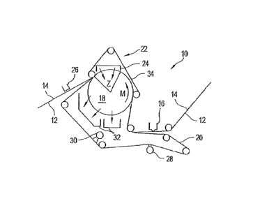
structure is that it can be utilized on rebuilt machines as in the case of
machines which do
not have any cantilever arrangements that allow for the use of endless
fabrics. The yarns
used for the dewatering fabric can also have different shapes, e.g., flat
yarns or elliptical
yarns, but are preferably round yarns. The yarns can also be mono yarns or
twisted yarns
or different combinations thereof. The yarns can additionally also be
multifilament yarns of
mainly polyamid (e.g., PA 6; PA 6.6; PA 6.12; and so on). Other different
polymeric
materials, whether natural or artificial, can also be used in specific
circumstances. The
yarns can further also be one or more component yarns in order to provide
certain
properties. For example, a two component yarn utilizing PA 6 and sheath PU can
be
advantageous because both materials can provide unique benefits. In this case,
the PA
will provide strength in the yarn direction and the PU will provide additional
void volume
and, due to the material properties, a higher resilience.
[0064] Nano particles can be added to the materials in the yarns and/or to
other
parts of the structure such as the fibers and membranes. Membrane materials
(such as
spectra) can be used in the fabric as in the case in conventional felts. Such
structures can
24
CA 02650432 2008-10-24
WO 2007/124966 PCT/EP2007/051198
provide good void volume and permeability in all paper grades. Based on the
high amount
of highly resilient material (when using e.g. PU), the overall resilience is
much higher than
needed on most conventional arrangements. Such membranes can have very
different
properties with regard to materials, open areas, caliper, substructures,
strength, form,
amount and size of pores, and so on. It is also possible for the structure to
utilize the
combination of a membrane and a laminated non-woven portion.
[0065] Non-woven structures can also be utilized. In this regard, the
structure can
utilize Vector technology, wherein a course non-woven substrate is used having
a wide
weight range from between approximately 100 g/m2 to approximately 500 g/m2.
This
structure can also contain fibers which can be greater than approximately 140
dtex or less
than approximately 140 dtex. The non-woven structure can also be in the form
of a single
component or several components. Moreover, even if a single component is
utilized, it can
utilize different materials, shapes, and so on.
[0066] Other structures can also be utilized for the base substrate such
as a link
fabric or a compound link fabric on which, for example, a porous media can be
three-
dimensionally extruded, sintered, and so on. Such a structure would allow the
use of other
available technologies like click systems (father ¨ mother systems).
[0067] The fibrous portion of the structure is a porous structure arranged
on the
base substrate and on one or both sides of the fabric. This portion contacts
the paper
sheet unlike the base structure which, in most cases, does not directly
contact the paper
sheet. One appropriate form of the fibrous portion would include fibers such
as polymeric
(natural and/or artificial) fibers. The fibrous portion can utilize one
component fibers as
well as a two or more component fibers. The fibers can be in the range of
between
CA 02650432 2008-10-24
WO 2007/124966 PCT/EP2007/051198
approximately 1.0 dtex and approximately 350 dtex, and are preferably between
approximately 1.7 dtex and approximately 100 dtex, and most preferably between
approximately 2.2 dtex and approximately 40 dtex. Of course, other fibers
types and sizes
can be utilized which are outside these ranges. The fibers can have a shape
such as
round, oval, flat, and can also be either uniform or irregular in shape (e.g.,
crocodile
fibers). The fibers can also be made from materials which allow for splitting
of the fibers
either in during the manufacturing process or during the run on the paper
machine.
Materials which can be used for the fibers (whether splitable or nonsplitable)
can be, e.g.,
PA, PES, PET and PU. The fibers can also be core sheath or side by side
structures, and
so on. The fibers can also, of course, be any type and shape which is utilized
in the prior
art and can be utilized based on the benefits they provide.
[0068] The fibers can be used as batt and/or can be arranged in pre-
processed
layers. Such fibers can also be treated chemically to achieve a certain
surface energy
(i.e., they can be hydrophilic or hydrophobic). The treatment can take place
for one or
more layers. Alternatively, the entire dewatering fabric can be so treated
chemically. One
or more of the layers of a multi-layered fibrous portion can even be treated
differently
depending on their properties or depending on the desired properties of the
layers. The
use of different fibers in different layers can lead to distinctive and very
different partial
densities in the dewatering fabric over a width of the structure. Preferably,
the fabric
utilizes fibers in at least one later of batt on at least one side of the
dewatering fabric.
[0069] Another way to make the porous media portion of the fibrous portion
utilizes
soluble materials which are mixed with unsoluble materials. The process can
ensure that
the soluble material is dissolved in order to create specific permeability.
This can be
combined with the use, for example, of one or more types of fibrous systems.
26
CA 02650432 2008-10-24
WO 2007/124966 PCT/EP2007/051198
[0070] Particle technology can also be utilized wherein particles are
deposited and
connected (using e.g., sintering, e-process, etc.) in order to form or modify
the porous
media. Specific modifications of the two sides of the dewatering fabric can
increase and/or
improve the runability. The paper contacting side of the dewatering fabric can
have a
surface which is configured to match the pattern of the TAD fabric.
Furthermore, the
opposite side of the fabric can have a surface that is configured to match the
shape/surface of the tension belt.
[0071] The use of thermoplastic materials can also be utilized on one of
more
surfaces of the fabric as well as within the internal structure of the fabric.
Such materials
can improve certain properties of the fabric such as abrasion resistance and
resilience.
Certain properties of the dewatering fabric can be achieved using different
processes. For
example, the fabric can be subjected to processes which remove material (e.g.,
grinding)
as well as processes which add material (e.g., sintering, printing, etc.) and
so on. The use
of physical or chemical processes allow both the surfaces of the dewatering
fabric as well
as the interior thereof to be modified as desired.
[0072] The fibrous portion and substrate base can be connected and/or
laminated
together by either physical or chemical connection systems. Such connections
can be
utilized between different materials and between layers of the fabric.
[0073]The following are non-limiting characteristics and/or properties of the
dewatering
fabric: the caliper can be between approximately 0.1 mm and approximately 15
mm, are
preferably between approximately 1.0 mm and approximately 10 mm, and most
preferably
between approximately 1.5 mm and approximately 2.5 mm; the permeability can be
27
CA 02650432 2008-10-24
WO 2007/124966 PCT/EP2007/051198
between approximately 1 cfm and approximately 500 cfm, is preferably between
approximately 5 cfm and approximately 100 cfm, is most preferably between
approximately
cfm and approximately 50 cfm, and is still most preferably between
approximately 15
cfm and approximately 25 cfm; the overall density can be between approximately
0.2 g/cm3
and approximately 1.10 g/cm3, is preferably between approximately 0.3 g/cm3
and
approximately 0.8 g/cm3, and is most preferably between approximately 0.4
g/cm3 and
approximately 0.7 g/cm3; the product weight range can be between approximately
100 g/m2
and approximately 3000 g/m2, is preferably between approximately 800 g/m2 and
approximately 2200 g/m2, is most preferably between approximately 1000 g/m2
and
approximately 1750 g/m2, is still more preferably between approximately 1000
g/m2 and
approximately 1400 g/m2. The dewatering fabric can also comprise at least one
layer that
is polar and/or at least one layer that is non-polar, and/or at least one
layer that is
hydrophobic, and/or at least one layer that is hydrophilic.
[0074] One purpose of the dewatering is to dewater the sheet in a long
extended
press nip. This allows additional air/steam to act upon the sheet and improves
dewatering.
The dewatering fabric of the invention should be distinguished from the
typical TAD fabric
which is very much more open, or a rigid construction, and has distinctly less
fine face than
the dewatering fabric of the invention.
BRIEF DESCRIPTION OF THE DRAWINGS
[0075] The above-mentioned and other features and advantages of this
invention,
and the manner of attaining them, will become more apparent and the invention
will be
better understood by reference to the following description of an embodiment
of the
invention taken in conjunction with the accompanying drawings, wherein:
28
CA 02650432 2008-10-24
WO 2007/124966 PCT/EP2007/051198
Fig. 1 is a cross-sectional schematic diagram of an advanced dewatering system
with an embodiment of a belt press according to the present invention;
Fig. 2 is a surface view of one side of a permeable belt of the belt press of
Fig. 1;
Fig. 3 is a view of an opposite side of the permeable belt of Fig. 2;
Fig. 4 is cross-section view of the permeable belt of Figs. 2 and 3;
Fig. 5 is an enlarged cross-sectional view of the permeable belt of Figs. 2-4;
Fig. 5a is an enlarged cross-sectional view of the permeable belt of Figs. 2-4
and
illustrating optional triangular grooves;
Fig. 5b is an enlarged cross-sectional view of the permeable belt of Figs. 2-4
and
illustrating optional semi-circular grooves;
Fig. 5c is an enlarged cross-sectional view of the permeable belt of Figs. 2-4
illustrating optional trapezoidal grooves;
Fig. 6 is a cross-sectional view of the permeable belt of Fig. 3 along section
line
B-B;
Fig. 7 is a cross-sectional view of the permeable belt of Fig. 3 along section
line
A-A;
Fig. 8 is a cross-sectional view of another embodiment of the permeable belt
of Fig.
3 along section line B-B;
Fig. 9 is a cross-sectional view of another embodiment of the permeable belt
of Fig.
3 along section line A-A;
Fig. 10 is a surface view of another embodiment of the permeable belt of the
present invention;
Fig. 11 is a side view of a portion of the permeable belt of Fig. 10;
Fig. 12 is a cross-sectional schematic diagram of still another advanced
dewatering
system with an embodiment of a belt press according to the present
invention;
29
CA 02650432 2008-10-24
WO 2007/124966 PCT/EP2007/051198
Fig. 13 is an enlarged partial view of one dewatering fabric which can be used
on
the advanced dewatering systems of the present invention;
Fig. 14 is an enlarged partial view of another dewatering fabric which can be
used
on the advanced dewatering systems of the present invention;
Fig. 15 is a exaggerated cross-sectional schematic diagram of one embodiment
of a
pressing portion of the advanced dewatering system according to the present
invention;
Fig. 16 is a exaggerated cross-sectional schematic diagram of another
embodiment
of a pressing portion of the advanced dewatering system according to the
present invention;
Fig. 17 is a cross-sectional schematic diagram of still another advanced
dewatering
system with another embodiment of a belt press according to the present
invention;
Fig. 18 is a partial side view of an optional permeable belt which may be used
in the
advanced dewatering systems of the present invention;
Fig. 19 is a partial side view of another optional permeable belt which may be
used
in the advanced dewatering systems of the present invention;
Fig. 20 is a cross-sectional schematic diagram of still another advanced
dewatering
system with an embodiment of a belt press which uses a pressing shoe
according to the present invention;
Fig. 21 is a cross-sectional schematic diagram of still another advanced
dewatering
system with an embodiment of a belt press which uses a press roll according
to the present invention;
Figs. 22a-b illustrate one way in which the contact area can be measured;
Fig. 23a illustrates an area of an Ashworth metal belt which can be used in
the
invention. The portions of the belt which are shown in black represent the
CA 02650432 2008-10-24
WO 2007/124966 PCT/EP2007/051198
contact area whereas the portions of the belt shown in white represent the
non-contact area;
Fig. 23b illustrates an area of a Cambridge metal belt which can be used in
the
invention. The portions of the belt which are shown in black represent the
contact area whereas the portions of the belt shown in white represent the
non-contact area;
Fig. 23c illustrates an area of a Voith Fabrics link fabric which can be used
in the
invention. The portions of the belt which are shown in black represent the
contact area whereas the portions of the belt shown in white represent the
non-contact area;
Fig. 24 is a cross-sectional schematic diagram of a machine or system which
utilizes
a belt press and a dewatering fabric according to the present invention; and
Fig. 25 shows one non-limiting example of the dewatering fabric which can be
used
to produce tissue or towel in, e.g., a TAD machine or an ATMOS system.
[0076] Corresponding reference characters indicate corresponding parts
throughout
the several views. The exemplary embodiments set out herein illustrate one or
more
acceptable or preferred embodiments of the invention, and such
exemplifications are not to
be construed as limiting the scope of the invention in any manner.
DETAILED DESCRIPTION OF THE INVENTION
[0077] The particulars shown herein are by way of example and for purposes
of
illustrative discussion of the embodiments of the present invention only and
are presented
in the cause of providing what is believed to be the most useful and readily
understood
description of the principles and conceptual aspects of the present invention.
In this
regard, no attempt is made to show structural details of the present invention
in more detail
31
CA 02650432 2008-10-24
WO 2007/124966 PCT/EP2007/051198
than is necessary for the fundamental understanding of the present invention,
the
description is taken with the drawings making apparent to those skilled in the
art how the
forms of the present invention may be embodied in practice.
[0078] Referring now to the drawings, and more particularly to Fig. 1,
there is shown
an advanced dewatering system 10 for processing a fibrous web 12. System 10
includes a
fabric 14, a suction box 16, a vacuum roll 18, a dewatering fabric 20, a belt
press assembly
22, a hood 24 (which may be a hot air hood), a pick up suction box 26, a Uhle
box 28, one
or more shower units 30, and one or more savealls 32. The fibrous material web
12 enters
system 10 generally from the right as shown in Fig. 1. Fibrous web 12 is a
previously
formed web (i.e., previously formed by a mechanism which is not shown) which
is placed
on the fabric 14. As is evident from Fig. 1, the suction device 16 provides
suctioning to
one side of the web 12, while the suction roll 18 provides suctioning to an
opposite side of
the web 12.
[0079] Fibrous web 12 is moved by fabric 14 in a machine direction M past
one or
more guide rolls and then past the suction box 16. At the vacuum box 16,
sufficient
moisture is removed from web 12 to achieve a solids level of between
approximately 15%
and approximately 25% on a typical or nominal 20 gram per square meter (gsm)
web
running. The vacuum at the box 16 provides between approximately -0.2 to
approximately
-0.8 bar vacuum, with a preferred operating level of between approximately -
0.4 to
approximately -0.6 bar.
[0080] As fibrous web 12 proceeds along the machine direction M, it comes
into
contact with a dewatering fabric 20. The dewatering fabric 20 can be an
endless
circulating belt which is guided by a plurality of guide rolls and is also
guided around the
32
CA 02650432 2008-10-24
WO 2007/124966 PCT/EP2007/051198
suction roll 18. The dewatering belt 20 can be a dewatering fabric of the type
shown and
described in Figs. 13 or 14 herein. The dewatering fabric 20 can also
preferably be a felt.
The web 12 then proceeds toward vacuum roll 18 between the fabric 14 and the
dewatering fabric 20. The vacuum roll 18 rotates along the machine direction M
and is
operated at a vacuum level of between approximately -0.2 to approximately -0.8
bar with a
preferred operating level of at least approximately -0.4 bar, and most
preferably
approximately -0.6 bar. By way of non-limiting example, the thickness of the
vacuum roll
shell of roll 18 may be in the range of between approximately 25 mm and
approximately 75
mm. The mean airflow through the web 12 in the area of the suction zone Z can
be
approximately 150 m3/min per meter of machine width. The fabric 14, web 12 and
dewatering fabric 20 are guided through a belt press 22 formed by the vacuum
roll 18 and
a permeable belt 34. As is shown in Fig. 1, the permeable belt 34 is a single
endlessly
circulating belt which is guided by a plurality of guide rolls and which
presses against the
vacuum roll 18 so as to form the belt press 22.
[0081] The upper fabric 14 transports the web 12 to and from the belt
press system
22. The web 12 lies in the three-dimensional structure of the upper fabric 14,
and
therefore it is not flat but has also a three-dimensional structure, which
produces a high
bulky web. The lower fabric 20 is also permeable. The design of the lower
fabric 20 is
made to be capable of storing water. The lower fabric 20 also has a smooth
surface. The
lower fabric 20 is preferably a felt with a batt layer. The diameter of the
batt fibers of the
lower fabric 20 are equal to or less than approximately 11 dtex, and can
preferably be
equal to or lower than approximately 4.2 dtex, or more preferably be equal to
or less than
approximately 3.3 dtex. The batt fibers can also be a blend of fibers. The
lower fabric 20
can also contain a vector layer which contains fibers from approximately 67
dtex, and can
also contain even courser fibers such as, e.g., approximately 100 dtex,
approximately 140
33
CA 02650432 2008-10-24
WO 2007/124966 PCT/EP2007/051198
dtex, or even higher dtex numbers. This is important for the good absorption
of water.
The wetted surface of the batt layer of the lower fabric 20 and/or of the
lower fabric itself
can be equal to or greater than approximately 35 m2/m2 felt area, and can
preferably be
equal to or greater than approximately 65 m2/m2 felt area, and can most
preferably be
equal to or greater than approximately 100 m2/m2 felt area. The specific
surface of the
lower fabric 20 should be equal to or greater than approximately 0.04 m2/g
felt weight, and
can preferably be equal to or greater than approximately 0.065 m2/g felt
weight, and can
most preferably be equal to or greater than approximately 0.075 m2/g felt
weight. This is
important for the good absorption of water. The dynamic stiffness K* [N/mm] as
a value for
the compressibility is acceptable if less than or equal to 100,000 N/mm,
preferable
compressibility is less than or equal to 90,000 N/mm, and most preferably the
compressibility is less than or equal to 70,000 N/mm. The compressibility
(thickness
change by force in mm/N) of the lower fabric 20 should be considered. This is
important in
order to dewater the web efficiently to a high dryness level. A hard surface
would not
press the web 12 between the prominent points of the structured surface of the
upper
fabric. On the other hand, the felt should not be pressed too deep into the
three-dimensional structure to avoid loosing bulk and therefore quality, e.g.,
water holding
capacity.
[0082] The circumferential length of vacuum zone Z can be between
approximately
200 mm and approximately 2500 mm, and is preferably between approximately 800
mm
and approximately 1800 mm, and an even more preferably between approximately
1200
mm and approximately 1600 mm. The solids content leaving vacuum roll 18 in web
12 will
vary between approximately 25% to approximately 55% depending on the vacuum
pressures and the tension on permeable belt, as well as the length of vacuum
zone Z and
the dwell time of web 12 in vacuum zone Z. The dwell time of web 12 in vacuum
zone Z is
34
CA 02650432 2008-10-24
WO 2007/124966 PCT/EP2007/051198
sufficient to result in this solids range of between approximately 25% and
approximately
55%.
[0083] With reference to Figs. 2-5, there is shown details of one
embodiment of the
permeable belt 34 of belt press 22. The belt 34 includes a plurality of
through holes or
through openings 36. The holes 36 are arranged in a hole pattern 38, of which
Fig. 2
illustrates one non-limiting example thereof. As illustrated in Figs. 3-5, the
belt 34 includes
grooves 40 arranged on one side of belt 34, i.e., the outside of the belt 34
or the side
which contacts the fabric 14. The permeable belt 34 is routed so as to engage
an upper
surface of the fabric 14 and thereby acts to press the fabric 14 against web
12 in the belt
press 22. This, in turn, causes web 12 to be pressed against the fabric 20,
which is
supported thereunder by the vacuum roll 18. As this temporary coupling or
pressing
engagement continues around the vacuum roll 18 in the machine direction M, it
encounters
a vacuum zone Z. The vacuum zone Z receives air flow from the hood 24, which
means
that air passes from the hood 24, through the permeable belt 34, through the
fabric 14, and
through drying web 12 and finally through the belt 20 and into the zone Z. In
this way,
moisture is picked up from the web 12 and is transferred through the fabric 20
and through
a porous surface of vacuum roll 18. As a result, the web 12 experiences or is
subjected to
both pressing and airflow in a simultaneous manner. Moisture drawn or directed
into
vacuum roll 18 mainly exits by way of a vacuum system (not shown). Some of the
moisture
from the surface of roll 18, however, is captured by one or more savealls 32
which are
located beneath vacuum roll 18. As web 12 leaves the belt press 22, the fabric
20 is
separated from the web 12, and the web 12 continues with the fabric 14 past
vacuum pick
up device 26. The device 26 additionally suctions moisture from the fabric 14
and the web
12 so as to stabilize the web 12.
CA 02650432 2008-10-24
WO 2007/124966 PCT/EP2007/051198
[0084] The fabric 20 proceeds past one or more shower units 30. These
units 30
apply moisture to the fabric 20 in order to clean the fabric 20. The fabric 20
then proceeds
past a Uhle box 28, which removes moisture from fabric 20.
[0085] The fabric 14 can be a structured fabric 14, i.e., it can have a
three
dimensional structure that is reflected in web 12, whereby thicker pillow
areas of the web
12 are formed. The structured fabric 14 may have, e.g., approximately 44 mesh,
between
approximately 30 mesh and approximately 50 mesh for towel paper, and between
approximately 50 mesh and approximately 70 mesh for toilet paper. These pillow
areas
are protected during pressing in the belt press 22 because they are within the
body of the
structured fabric 14. As such, the pressing imparted by belt press assembly 22
upon the
web 12 does not negatively impact web or sheet quality. At the same time, it
increases the
dewatering rate of vacuum roll 18. If the belt 34 is used in a No Press / Low
Press
apparatus, the pressure can be transmitted through a dewatering fabric, also
known as a
press fabric. In this case, the web 12 is not protected with a structured
fabric 14. However,
the use of the belt 34 is still advantageous because the press nip is much
longer than a
conventional press, which results in a lower specific pressure and less or
reduced sheet
compaction of the web 12.
[0086] The permeable belt 34 shown in Figs. 2-5 can be made of metal,
stainless
steel and/or a polymeric material (or a combination of these materials), and
can provide a
low level of pressing in the range of between approximately 30 KPa and
approximately 150
KPa, and preferably greater than approximately 70 KPa. Thus, if the suction
roll 18 has a
diameter of approximately 1.2 meter, the fabric tension for belt 34 can be
greater than
approximately 30 KN/m, and preferably greater than approximately 50 KN/m. The
pressing
length of permeable belt 34 against the fabric 14, which is indirectly
supported by vacuum
36
CA 02650432 2008-10-24
WO 2007/124966 PCT/EP2007/051198
roll 18, can be at least as long as, or longer than, the circumferential
length of the suction
zone Z of roll 18. Of course, the invention also contemplates that the contact
portion of
permeable belt 34 (i.e., the portion of belt which is guided by or over the
roll 18) can be
shorter than suction zone Z.
[0087] As is shown in Figs. 2-5, the permeable belt 34 has a pattern 38 of
through
holes 36, which may, for example, be formed by drilling, laser cutting, etched
formed, or
woven therein. The permeable belt 34 may also be essentially monoplaner, i.e.,
formed
without the grooves 40 shown in Figs. 3-5. The surface of the belt 34 which
has the
grooves 40 can be placed in contact with the fabric 14 along a portion of the
travel of
permeable belt 34 in a belt press 22. Each groove 40 connects with a set or
row of holes
36 so as to allow the passage and distribution of air in the belt 34. Air is
thus distributed
along grooves 40. The grooves 40 and openings 36 thus constitute open areas of
the belt
34 and are arranged adjacent to contact areas, i.e., areas where the surface
of belt 34
applies pressure against the fabric 14 or the web 12. Air enters the permeable
belt 34
through the holes 36 from a side opposite that of the side containing the
grooves 40, and
then migrates into and along the grooves 40 and also passes through the fabric
14, the
web 12 and the fabric 20. As can be seen in Fig. 3, the diameter of holes 36
is larger than
the width of the grooves 40. While circular holes 36 are preferred, they need
not be
circular and can have any shape or configuration which performs the intended
function.
Moreover, although the grooves 40 are shown in Fig. 5 as having a generally
rectangular
cross-section, the grooves 40 may have a different cross-sectional contour,
such as, e.g.,
a triangular cross-section as shown in Fig. 5a, a trapezoidal cross-section as
shown in Fig.
Sc, and a semicircular or semi-elliptical cross-section as shown in Fig. 5b.
The
combination of the permeable belt 34 and the vacuum roll 18, is a combination
that has
been shown to increase sheet solids level by at least approximately 15%.
37
CA 02650432 2013-10-10
[0088] By way of non-limiting example, the width of the generally
parallel grooves 40
shown in Fig. 3 can be approximately 2.5 mm and the depth of the grooves 40
measured
from the outside surface (i.e.., the surface contacting belt 14) can be
approximately 2.5
mm. The diameter of the through openings 36 can be approximately 4 mm. The
distance,
Measured (of course) in the width direction, between the grooves 40 can be
approximately
mm. The longitudinal distance (measured from the center-lines) between the
openings
36 can be approximately 6.5 mm. The distance (measured from the center-lines
in a
direction of the width) between the openings 36, rows of openings, or grooves
40 can be
approximately 7.5 mm. The openings 36 in every other row of openings can be
offset by
approximately half so that the longitudinal distance between adjacent openings
can be half
the distance between openings 36 of the same row, e.g., half of 6.5 mm. The
overall width
of the belt 34 can be approximately 160 mm more than the paper width and the
overall
length of the endlessly circulating belt 34 can be approximately 20 m. The
tension limits of
the belt 34 can be between, e.g., approximately 30 KN/m and approximately 50
KN/m.
[00891 Figs. 6-11 show other non-limiting embodiments of the permeable
belt 34
which can be used in a belt press 22 of the type shown in Fig. 1. The belt 34
shown Figs.
6-9 may be an extended nip press belt made of a flexible reinforced
polyurethane 42. It
may also be a spiral link fabric 48 of the type shown in Figs. 10 and 11. The
permeable
belt 34 may also be a spiral link fabric of the type described in GB 2 141
749Aõ,
The
permeable belt 34 shown in Figs. 6-9 also provides a low level of pressing in
the range of
between approximately 30 KPa and approximately 150 KPa, and preferably greater
than
approximately 70 KPa. This allows, for example, a suction roll with a 1.2
meter diameter to
provide a fabric tension of greater than approximately 30 KN/m, and preferably
greater
than approximately 50 KN/m, it can also be greater than approximately 60 KN/m,
and also
38
CA 02650432 2008-10-24
WO 2007/124966 PCT/EP2007/051198
greater than approximately 80 KN/m. The pressing length of the permeable belt
34 against
the fabric 14, which is indirectly supported by vacuum roll 18, can be at
least as long as or
longer than suction zone Z in roll 18. Of course, the invention also
contemplates that the
contact portion of permeable belt 34 can be shorter than suction zone Z.
[0090] With reference to Figs. 6 and 7, the belt 34 can have the form of a
polyurethane matrix 42 which has a permeable structure. The permeable
structure can
have the form of a woven structure with reinforcing machine direction yams 44
and cross
direction yarns 46 at least partially embedded within polyurethane matrix 42.
The belt 34
also includes through holes 36 and generally parallel longitudinal grooves 40
which
connect the rows of openings as in the embodiment shown in Figs 3-5.
[0091] Figs. 8 and 9 illustrate still another embodiment for the belt 34.
The belt 34
includes a polyurethane matrix 42 which has a permeable structure in the form
of a spiral
link fabric 48. The link fabric 48 is at least partially embedded within
polyurethane matrix
42. Holes 36 extend through belt 34 and may at least partially sever portions
of spiral link
fabric 48. Generally parallel longitudinal grooves 40 also connect the rows of
openings
and in the above-noted embodiments. The spiral link fabric 34 described in
this
specification can also be made of a polymeric material and/or is preferably
tensioned in
the range of between approximately 30 KN/m and 80 KN/m, and preferably between
approximately 35 KN/m and approximately 50 KN/m. This provides improved
runnability of
the belt, which is not able to withstand high tensions, and is balanced with
sufficient
dewatering of the paper web.
[0092] By way of non-limiting example, and with reference to the
embodiments
shown in Figs. 6-9, the width of the generally parallel grooves 40 shown in
Fig. 7 can be
39
CA 02650432 2008-10-24
WO 2007/124966 PCT/EP2007/051198
approximately 2.5 mm and the depth of the grooves 40 measured from the outside
surface
(i.e.., the surface contacting belt 14) can be approximately 2.5 mm. The
diameter of the
through openings 36 can be approximately 4 mm. The distance, measured (of
course) in
the width direction, between the grooves 40 can be approximately 5 mm. The
longitudinal
distance (measured from the center-lines) between the openings 36 can be
approximately
6.5 mm. The distance (measured from the center-lines in a direction of the
width) between
the openings 36, rows of openings, or grooves 40 can be approximately 7.5 mm.
The
openings 36 in every other row of openings can be offset by approximately half
so that the
longitudinal distance between adjacent openings can be half the distance
between
openings 36 of the same row, e.g., half of 6.5 mm. The overall width of the
belt 34 can be
approximately 160 mm more than the paper width and the overall length of the
endlessly
circulating belt 34 can be approximately 20 m.
[0093] Figs. 10 and 11 shows yet another embodiment of the permeable belt
34. In
this embodiment, yarns 50 are interlinked by entwining generally spiral woven
yarns 50
with cross yams 52 in order to form link fabric 48. Non-limiting examples of
this belt can
include a Ashworth Metal Belt, a Cambridge Metal belt and a Voith Fabrics Link
Fabric and
are shown in Figs. 23a-c. The spiral link fabric described in this
specification can also be
made of a polymeric material and/or is preferably tensioned in the range of
between
approximately 30 KN/m and 80 KN/m, and preferably between approximately 35
KN/m and
approximately 50 KN/m. This provides improved runnability of the belt 34,
which is not
able to withstand high tensions, and is balanced with sufficient dewatering of
the paper
web. Fig. 23a illustrates an area of the Ashworth metal belt which is
acceptable for use in
the invention. The portions of the belt which are shown in black represent the
contact area
whereas the portions of the belt shown in white represent the non-contact
area. The
Ashworth belt is a metal link belt which is tensioned at approximately 60
KN/m. The open
CA 02650432 2008-10-24
WO 2007/124966 PCT/EP2007/051198
area may be between approximately 75% and approximately 85%. The contact area
may
be between approximately 15% and approximately 25%. Fig. 23b illustrates an
area of a
Cambridge metal belt which is preferred for use in the invention. Again, the
portions of the
belt which are shown in black represent the contact area whereas the portions
of the belt
shown in white represent the non-contact area. The Cambridge belt is a metal
link belt
which is tensioned at approximately 50 KN/m. The open area may be between
approximately 68% and approximately 76%. The contact area may be between
approximately 24% and approximately 32%. Finally, Fig. 23c illustrates an area
of a Voith
Fabrics link fabric which is most preferably used in the invention. The
portions of the belt
which are shown in black represent the contact area whereas the portions of
the belt
shown in white represent the non-contact area. The Voith Fabrics belt may be a
polymer
link fabric which is tensioned at approximately 40 KN/m. The open area may be
between
approximately 51% and approximately 62%. The contact area may be between
approximately 38% and approximately 49%.
[0094] As with the previous embodiments, the permeable belt 34 shown in
Figs. 10
and 11 is capable of running at high running tensions of between at least
approximately 30
KN/m and at least approximately 50 KN/m or higher and may have a surface
contact area
of approximately 10% or greater, as well as an open area of approximately 15%
or greater.
The open area may be approximately 25% or greater. The composition of
permeable belt
34 shown in Figs. 10 and 11 may include a thin spiral link structure having a
support layer
within permeable belt 34. The spiral link fabric can be made of metal and/or
stainless
steel. Further, permeable belt 34 may be a spiral link fabric 34 having a
contact area of
between approximately 15% and approximately 55 c1/0, and an open area of
between
approximately 45% to approximately 85%. More preferably, the spiral link
fabric 34 may
have an open area of between approximately 50% and approximately 65%, and a
contact
41
CA 02650432 2008-10-24
WO 2007/124966 PCT/EP2007/051198
area of between approximately 35% and approximately 50%.
[0095] The process of using the advanced dewatering system (ADS) 10 shown
in
Fig. 1 will now be described. The ADS 10 utilizes belt press 22 to remove
water from web
12 after the web is initially formed prior to reaching belt press 22. A
permeable belt 34 is
routed in the belt press 22 so as to engage a surface of fabric 14 and thereby
press fabric
14 further against web 12, thus pressing the web 12 against fabric 20, which
is supported
thereunder by a vacuum roll 18. The physical pressure applied by the belt 34
places some
hydraulic pressure on the water in web 12 causing it to migrate toward fabrics
14 and 20.
As this coupling of web 12 with fabrics 14 and 20, and belt 34 continues
around vacuum
roll 18, in machine direction M, it encounters a vacuum zone Z through which
air is passed
from a hood 24, through the permeable belt 34, through the fabric 14, so as to
subject the
web 12 to drying. The moisture picked up by the air flow from the web 12
proceeds further
through fabric 20 and through a porous surface of vacuum roll 18. In the
permeable belt
34, the drying air from the hood 24 passes through holes 36, is distributed
along grooves
40 before passing through the fabric 14. As web 12 leaves belt press 22, the
belt 34
separates from the fabric 14. Shortly thereafter, the fabric 20 separates from
web 12, and
the web 12 continues with the fabric 14 past vacuum pick up unit 26, which
additionally
suctions moisture from the fabric 14 and the web 12.
[0096] The permeable belt 34 of the present invention is capable of
applying a line
force over an extremely long nip, i.e., 10 times longer than for a shoe press,
thereby
ensuring a long dwell time in which pressure is applied against web 12 as
compared to a
standard shoe press. This results in a much lower specific pressure, i.e., 20
times lower
than for a shoe press, thereby reducing the sheet compaction and enhancing
sheet quality.
The present invention further allows for a simultaneous vacuum and pressing
dewatering
with airflow through the web at the nip itself.
42
CA 02650432 2008-10-24
WO 2007/124966 PCT/EP2007/051198
[0097] Fig. 12 shows another an advanced dewatering system 110 for
processing a
fibrous web 112. The system 110 includes an upper fabric 114, a vacuum roll
118, a
dewatering fabric 120, a belt press assembly 122, a hood 124 (which may be a
hot air
hood), a Uhle box 128, one or more shower units 130, one or more savealls 132,
one or
more heater units 129. The fibrous material web 112 enters system 110
generally from the
right as shown in Fig. 12. The fibrous web 112 is a previously formed web
(i.e., previously
formed by a mechanism not shown) which is placed on the fabric 114. As was the
case in
Fig. 1, a suction device (not shown but similar to device 16 in Fig. 1) can
provide
suctioning to one side of the web 112, while the suction roll 118 provides
suctioning to an
opposite side of the web 112.
[0098] The fibrous web 112 is moved by fabric 114 in a machine direction M
past
one or more guide rolls. Although it may not be necessary, before reaching the
suction
roll, the web 112 may have sufficient moisture is removed from web 112 to
achieve a
solids level of between approximately 15% and approximately 25% on a typical
or nominal
20 gram per square meter (gsm) web running. This can be accomplished by vacuum
at a
box (not shown) of between approximately -0.2 to approximately -0.8 bar
vacuum, with a
preferred operating level of between approximately -0.4 to approximately -0.6
bar.
[0099] As fibrous web 112 proceeds along the machine direction M, it comes
into
contact with a dewatering fabric 120. The dewatering fabric 120 can be an
endless
circulating belt which is guided by a plurality of guide rolls and is also
guided around a
suction roll 118. The web 112 then proceeds toward vacuum roll 118 between the
fabric
114 and the dewatering fabric 120. The vacuum roll 118 can be a driven roll
which rotates
along the machine direction M and is operated at a vacuum level of between
approximately
43
CA 02650432 2008-10-24
WO 2007/124966 PCT/EP2007/051198
-0.2 to approximately -0.8 bar with a preferred operating level of at least
approximately -0.4
bar. By way of non-limiting example, the thickness of the vacuum roll shell of
roll 118 may
be in the range of between 25 mm and 75 mm. The mean airflow through the web
112 in
the area of the suction zone Z can be approximately 150 m3/min per meter
machine width.
The fabric 114, web 112 and dewatering fabric 120 is guided through a belt
press 122
formed by the vacuum roll 118 and a permeable belt 134. As is shown in Fig.
12, the
permeable belt 134 is a single endlessly circulating belt which is guided by a
plurality of
guide rolls and which presses against the vacuum roll 118 so as to form the
belt press 122.
To control and/or adjust the tension of the belt 134, a tension adjusting roll
TAR is
provided as one of the guide rolls.
[0100] The circumferential length of vacuum zone Z can be between
approximately
200 mm and approximately 2500 mm, and is preferably between approximately 800
mm
and approximately 1800 mm, and an even more preferably between approximately
1200
mm and approximately 1600 mm. The solids leaving vacuum roll 118 in web 112
will vary
between approximately 25% and approximately 55% depending on the vacuum
pressures
and the tension on permeable belt as well as the length of vacuum zone Z and
the dwell
time of web 112 in vacuum zone Z. The dwell time of web 112 in vacuum zone Z
is
sufficient to result in this solids range of between approximately 25% to
approximately
55%.
[0101] The press system shown in Fig. 12 thus utilizes at least one upper
or first
permeable belt or fabric 114, at least one lower or second belt or fabric 120
and a paper
web 112 disposed therebetween, thereby forming a package which can be led
through the
belt press 122 formed by the roll 118 and the permeable belt 134. A first
surface of a
pressure producing element 134 is in contact with the at least one upper
fabric 114. A
44
CA 02650432 2008-10-24
WO 2007/124966 PCT/EP2007/051198
second surface of a supporting structure 118 is in contact with the at least
one lower fabric
120 and is permeable. A differential pressure field is provided between the
first and the
second surfaces, acting on the package of at least one upper and at least one
lower fabric
and the paper web therebetween. In this system, a mechanical pressure is
produced on
the package and therefore on the paper web 112. This mechanical pressure
produces a
predetermined hydraulic pressure in the web 112, whereby the contained water
is drained.
The upper fabric 114 has a bigger roughness and/or compressibility than the
lower fabric
120. An airflow is caused in the direction from the at least one upper 114 to
the at least
one lower fabric 120 through the package of at least one upper fabric 114, at
least one
lower fabric 120 and the paper web 112 therebetween.
[0102] The upper fabric 114 can be permeable and/or a so-called
"structured fabric".
By way of non-limiting examples, the upper fabric 114 can be e.g., a TAD
fabric. The hood
124 can also be replaced with a steam box which has a sectional construction
or design in
order to influence the moisture or dryness cross-profile of the web.
[0103] With reference to Fig. 13, the lower fabric 120 can be a membrane
or fabric
which includes a permeable base fabric BF and a lattice grid LG attached
thereto and
which is made of polymer such as polyurethane. The lattice grid LG side of the
fabric 120
can be in contact with the suction roll 118 while the opposite side contacts
the paper web
112. The lattice grid LG may be attached or arranged on the base fabric BF by
utilizing
various known procedures, such as, for example, an extrusion technique or a
screen
printing technique. As shown in Fig. 13, the lattice grid LG can also be
oriented at an
angle relative to machine direction yarns MDY and cross-direction yarns CDY.
Although
this orientation is such that no part of the lattice grid LG is aligned with
the machine
direction yarns MDY, other orientations such as that shown in Fig. 14 can also
be utilized.
CA 02650432 2008-10-24
WO 2007/124966 PCT/EP2007/051198
Although the lattice grid LG is shown as a rather uniform grid pattern, this
pattern can also
be discontinuous and/or non-symmetrical at least in part. Further, the
material between
the interconnections of the lattice structure may take a circuitous path
rather than being
substantially straight, as is shown in Fig. 13. Lattice grid LG can also be
made of a
synthetic, such as a polymer or specifically a polyurethane, which attaches
itself to the
base fabric BF by its natural adhesion properties. Making the lattice grid LG
of a
polyurethane provides it with good frictional properties, such that it seats
well against the
vacuum roll 118. This, then forces vertical airflow and eliminates any "x, y
plane" leakage.
The velocity of the air is sufficient to prevent any re-wetting once the water
makes it
through the lattice grid LG. Additionally, the lattice grid LG may be a thin
perforated
hydrophobic film having an air permeability of approximately 35 cfm or less,
preferably
approximately 25 cfm. The pores or openings of the lattice grid LG can be
approximately
15 microns. The lattice grid LG can thus provide good vertical airflow at high
velocity so
as to prevent rewet. With such a fabric 120, it is possible to form or create
a surface
structure that is independent of the weave patterns.
[0104] With reference to Fig. 14, it can be seen that the lower dewatering
fabric 120
can have a side which contacts the vacuum roll 118 which also includes a
permeable base
fabric BF and a lattice grid LG. The base fabric BF includes machine direction
multifilament yarns MDY (which could also be mono or twisted mono yarns or
combinations
of multifil and monofil twisted and untwisted yarns from equal or different
polymeric
materials) and cross-direction multifilament yarns CDY (which could also be
mono or
twisted mono yarns or combinations of multifil and monofil twisted and
untwisted yarns
from equal or different polymeric materials) and is adhered to the lattice
grid LG, so as to
form a so called "anti-rewet layer". The lattice grid can be made of a
composite material,
such as an elastomeric material, which may be the same as the as the lattice
grid
46
CA 02650432 2008-10-24
WO 2007/124966 PCT/EP2007/051198
described in Fig. 13. As can be seen in Fig. 14, the lattice grid LG can
itself include
machine direction yarns GMDY with an elastomeric material EM being formed
around
these yarns. The lattice grid LG may thus be composite grid mat formed on
elastomeric
material EM and machine direction yarns GMDY. In this regard, the grid machine
direction
yarns GMDY may be pre-coated with elastomeric material EM before being placed
in rows
that are substantially parallel in a mold that is used to reheat the
elastomeric material EM
causing it to re-flow into the pattern shown as grid LG in Fig. 14. Additional
elastomeric
material EM may be put into the mold as well. The grid structure LG, as
forming the
composite layer, in then connected to the base fabric BF by one of many
techniques
including the laminating of the grid LG to the permeable base fabric BF,
melting the
elastomeric coated yarn as it is held in position against the permeable base
fabric BF or by
re-melting the grid LG to the permeable base fabric BF. Additionally, an
adhesive may be
utilized to attach the grid LG to the permeable base fabric BF. The composite
layer LG
should be able to seal well against the vacuum roll 118 preventing "x,y plane"
leakage and
allowing vertical airflow to prevent rewet. With such a fabric, it is possible
to form or create
a surface structure that is independent of the weave patterns.
[0105] The belt 120 shown in Figs. 13 and 14 can also be used in place of
the belt
20 shown in the arrangement of Fig. 1.
[0106] Fig. 15 shows an enlargement of one possible arrangement in a
press. A
suction support surface SS acts to support the fabrics 120, 114, 134 and the
web 112.
The suction support surface SS has suction openings SO. The openings SO can
preferably be chamfered at the inlet side in order to provide more suction
air. The surface
SS may be generally flat in the case of a suction arrangement which uses a
suction box of
the type shown in, e.g., Fig. 16. Preferably, the suction surface SS is a
moving curved roll
47
CA 02650432 2008-10-24
WO 2007/124966 PCT/EP2007/051198
belt or jacket of the suction roll 118. In this case, the belt 134 can be a
tensioned spiral
link belt of the type already described herein. The belt 114 can be a
structured fabric and
the belt 120 can be a dewatering felt of the types described above. In this
arrangement,
moist air is drawn from above the belt 134 and through the belt 114, web 112,
and belt 120
and finally through the openings SO and into the suction roll 118. Another
possibility
shown in Fig. 16 provides for the suction surface SS to be a moving curved
roll belt or
jacket of the suction roll 118 and the belt 114 to be a SPECTRA membrane. In
this case,
the belt 134 can be a tensioned spiral link belt of the type already described
herein. The
belt 120 can be a dewatering felt of the types described above. In this
arrangement, also
moist air is drawn from above the belt 134 and through the belt 114, web 112,
and belt 120
and finally through the openings SO and into the suction roll 118.
[0107] Fig. 17 illustrates another way in which the web 112 can be
subjecting to
drying. In this case, a permeable support fabric SF (which can be similar to
fabrics 20 or
120) is moved over a suction box SB. The suction box SB is sealed with seals S
to an
underside surface of the belt SF. A support belt 114 has the form of a TAD
fabric and
carries the web 112 into the press formed by the belt PF, and pressing device
PD arranged
therein, and the support belt SF and stationary suction box SB. The
circulating pressing
belt PF can be a tensioned spiral link belt of the type already described
herein and/or of
the type shown in Figs. 18 and 19. The belt PF can also alternatively be a
groove belt
and/or it can also be permeable. In this arrangement, the pressing device PD
presses the
belt PF with a pressing force PF against the belt SF while the suction box SB
applies a
vacuum to the belt SF, web 112 and belt 114. During pressing, moist air can be
drawn
from at least the belt 114, web 112 and belt SF and finally into the suction
box SB.
[0108] The upper fabric 114 can thus transport the web 112 to and away
from the
48
CA 02650432 2008-10-24
WO 2007/124966 PCT/EP2007/051198
press and/or pressing system. The web 112 can lie in the three-dimensional
structure of
the upper fabric 114, and therefore it is not flat, but instead has also a
three-dimensional
structure, which produces a high bulky web. The lower fabric 120 is also
permeable. The
design of the lower fabric 120 is made to be capable of storing water. The
lower fabric 120
also has a smooth surface. The lower fabric 120 is preferably a felt with a
batt layer. The
diameter of the batt fibers of the lower fabric 120 can be equal to or less
than
approximately 11 dtex, and can preferably be equal to or lower than
approximately 4.2
dtex, or more preferably be equal to or less than approximately 3.3 dtex. The
batt fibers
can also be a blend of fibers. The lower fabric 120 can also contain a vector
layer which
contains fibers from at least approximately 67 dtex, and can also contain even
courser
fibers such as, e.g., at least approximately 100 dtex, at least approximately
140 dtex, or
even higher dtex numbers. This is important for the good absorption of water.
The wetted
surface of the batt layer of the lower fabric 120 and/or of the lower fabric
120 itself can be
equal to or greater than approximately 35 m2/m2 felt area, and can preferably
be equal to
or greater than approximately 65 m2/m2 felt area, and can most preferably be
equal to or
greater than approximately 100 m2/m2 felt area. The specific surface of the
lower fabric
120 should be equal to or greater than approximately 0.04 m2/g felt weight,
and can
preferably be equal to or greater than approximately 0.065 m2/g felt weight,
and can most
preferably be equal to or greater than approximately 0.075 m2/g felt weight.
This is
important for the good absorption of water.
[0109] The compressibility (thickness change by force in mm/N) of the
upper fabric
114 is lower than that of the lower fabric 120. This is important in order to
maintain the
three-dimensional structure of the web 112, i.e., to ensure that the upper
belt 114 is a stiff
structure.
49
CA 02650432 2008-10-24
WO 2007/124966 PCT/EP2007/051198
[0110] The resilience of the lower fabric 120 should be considered. The
density of
the lower fabric 120 should be equal to or higher than approximately 0.4
g/cm3, and is
preferably equal to or higher than approximately 0.5 g/cm3, and is ideally
equal to or higher
than approximately 0.53 g/cm3. This can be advantageous at web speeds of
greater than
1200 m/min. A reduced felt volume makes it easier to take the water away from
the felt
120 by the air flow, i.e., to get the water through the felt 120. Therefore
the dewatering
effect is smaller. The permeability of the lower fabric 120 can be lower than
approximately
80 cfm, preferably lower than 40 cfm, and ideally equal to or lower than 25
cfm. A reduced
permeability makes it easier to take the water away from the felt 120 by the
air flow, i.e., to
get the water through the felt 120. As a result, the re-wetting effect is
smaller. A too high
permeability, however, would lead to a too high air flow, less vacuum level
for a given
vacuum pump, and less dewatering of the felt because of the too open
structure.
[0111] The second surface of the supporting structure, i.e., the surface
supporting
the belt 120, can be flat and/or planar. In this regard, the second surface of
the supporting
structure SF can be formed by a flat suction box SB. The second surface of the
supporting
structure SF can also preferably be curved. For example, the second surface of
the
supporting structure SF can be formed or run over a suction roll 118 or
cylinder whose
diameter is, e.g., approximately 1 m. The suction device or cylinder 118 may
comprise at
least one suction zone Z. It may also comprise two suction zones Z1 and Z2 as
is shown
in Fig. 20. The suction cylinder 218 may also include at least one suction box
with at least
one suction arc. At least one mechanical pressure zone can be produced by at
least one
pressure field (i.e., by the tension of a belt) or through the first surface
by, e.g., a press
element. The first surface can be an impermeable belt 134, but with an open
surface
towards the first fabric 114, e.g., a grooved or a blind drilled and grooved
open surface, so
that air can flow from outside into the suction arc. The first surface can be
a permeable
CA 02650432 2008-10-24
WO 2007/124966 PCT/EP2007/051198
belt 134. The belt may have an open area of at least approximately 25%,
preferably
greater than approximately 35%, most preferably greater than approximately
50%. The
belt 134 may have a contact area of at least approximately 10%, at least
approximately
25%, and preferably between approximately 50% and approximately 85% in order
to have
a good pressing contact.
[0112] Fig. 20 shows another an advanced dewatering system 210 for
processing a
fibrous web 212. The system 210 includes an upper fabric 214, a vacuum roll
218, a
dewatering fabric 220 and a belt press assembly 222. Other optional features
which are
not shown include a hood (which may be a hot air hood or steam box), one or
more Uhle
boxes, one or more shower units, one or more savealls, and one or more heater
units, as
is shown in Figs. 1 and 12. The fibrous material web 212 enters system 210
generally
from the right as shown in Fig. 20. The fibrous web 212 is a previously formed
web (i.e.,
previously formed by a mechanism not shown) which is placed on the fabric 214.
As was
the case in Fig. 1, a suction device (not shown but similar to device 16 in
Fig. 1) can
provide suctioning to one side of the web 212, while the suction roll 218
provides
suctioning to an opposite side of the web 212.
[0113] The fibrous web 212 is moved by the fabric 214, which may be a TAD
fabric,
in a machine direction M past one or more guide rolls. Although it may not be
necessary,
before reaching the suction roll 218, the web 212 may have sufficient moisture
is removed
from web 212 to achieve a solids level of between approximately 15% and
approximately
25% on a typical or nominal 20 gram per square meter (gsm) web running. This
can be
accomplished by vacuum at a box (not shown) of between approximately -0.2 to
approximately -0.8 bar vacuum, with a preferred operating level of between
approximately -
0.4 to approximately -0.6 bar.
51
CA 02650432 2008-10-24
WO 2007/124966 PCT/EP2007/051198
[0114] As fibrous web 212 proceeds along the machine direction M, it comes
into
contact with a dewatering fabric 220. The dewatering fabric 220 ( which can be
any type
described herein) can be endless circulating belt which is guided by a
plurality of guide
rolls and is also guided around a suction roll 218. The web 212 then proceeds
toward
vacuum roll 218 between the fabric 214 and the dewatering fabric 220. The
vacuum roll
218 can be a driven roll which rotates along the machine direction M and is
operated at a
vacuum level of between approximately -0.2 to approximately -0.8 bar with a
preferred
operating level of at least approximately -0.5 bar. By way of non-limiting
example, the
thickness of the vacuum roll shell of roll 218 may be in the range of between
25 mm and 75
mm. The mean airflow through the web 212 in the area of the suction zones Z1
and Z2
can be approximately 150 m3/meter of machine width. The fabric 214, web 212
and
dewatering fabric 220 are guided through a belt press 222 formed by the vacuum
roll 218
and a permeable belt 234. As is shown in Fig. 20, the permeable belt 234 is a
single
endlessly circulating belt which is guided by a plurality of guide rolls and
which presses
against the vacuum roll 218 so as to form the belt press 122. To control
and/or adjust the
tension of the belt 234, one of the guide rolls may be a tension adjusting
roll. This
arrangement also includes a pressing device arranged within the belt 234. The
pressing
device includes a journal bearing JB, one or more actuators A, and one or more
pressing
shoes PS which are preferably perforated.
[0115] The circumferential length of at least vacuum zone Z2 can be
between
approximately 200 mm and approximately 2500 mm, and is preferably between
approximately 800 mm and approximately 1800 mm, and an even more preferably
between
approximately 1200 mm and approximately 1600 mm. The solids leaving vacuum
roll 218
52
CA 02650432 2008-10-24
WO 2007/124966 PCT/EP2007/051198
in web 212 will vary between approximately 25% and approximately 55% depending
on the
vacuum pressures and the tension on permeable belt 234 and the pressure from
the
pressing device PS/A/JB as well as the length of vacuum zone Z2, and the dwell
time of
web 212 in vacuum zone Z2. The dwell time of web 212 in vacuum zone Z2 is
sufficient to
result in this solids range of approximately 25% and approximately 55%.
[0116] Fig. 21 shows another an advanced dewatering system 310 for
processing a
fibrous web 312. The system 310 includes an upper fabric 314, a vacuum roll
318, a
dewatering fabric 320 and a belt press assembly 322. Other optional features
which are
not shown include a hood (which may be a hot air hood or steam box), one or
more Uhle
boxes, one or more shower units, one or more savealls, and one or more heater
units, as
is shown in Figs. 1 and 12. The fibrous material web 312 enters system 310
generally
from the right as shown in Fig. 21. The fibrous web 312 is a previously formed
web (i.e.,
previously formed by a mechanism not shown) which is placed on the fabric 314.
As was
the case in Fig. 1, a suction device (not shown but similar to device 16 in
Fig. 1) can
provide suctioning to one side of the web 312, while the suction roll 318
provides
suctioning to an opposite side of the web 312.
[0117] The fibrous web 312 is moved by fabric 314, which can be a TAD
fabric, in a
machine direction M past one or more guide rolls. Although it may not be
necessary,
before reaching the suction roll 318, the web 212 may have sufficient moisture
is removed
from web 212 to achieve a solids level of between approximately 15% and
approximately
25% on a typical or nominal 20 gram per square meter (gsm) web running. This
can be
accomplished by vacuum at a box (not shown) of between approximately -0.2 to
approximately -0.8 bar vacuum, with a preferred operating level of between
approximately -
0.4 to approximately -0.6 bar.
53
CA 02650432 2008-10-24
WO 2007/124966 PCT/EP2007/051198
[0118] As fibrous web 312 proceeds along the machine direction M, it comes
into
contact with a dewatering fabric 320. The dewatering fabric 320 ( which can be
any type
described herein) can be endless circulating belt which is guided by a
plurality of guide
rolls and is also guided around a suction roll 318. The web 312 then proceeds
toward
vacuum roll 318 between the fabric 314 and the dewatering fabric 320. The
vacuum roll
318 can be a driven roll which rotates along the machine direction M and is
operated at a
vacuum level of between approximately -0.2 to approximately -0.8 bar with a
preferred
operating level of at least approximately -0.5 bar. By way of non-limiting
example, the
thickness of the vacuum roll shell of roll 318 may be in the range of between
25 mm and 75
mm. The mean airflow through the web 312 in the area of the suction zones Z1
and Z2
can be approximately 150 m3/meter of machine width. The fabric 314, web 312
and
dewatering fabric 320 are guided through a belt press 322 formed by the vacuum
roll 318
and a permeable belt 334. As is shown in Fig. 21, the permeable belt 334 is a
single
endlessly circulating belt which is guided by a plurality of guide rolls and
which presses
against the vacuum roll 318 so as to form the belt press 322. To control
and/or adjust the
tension of the belt 334, one of the guide rolls may be a tension adjusting
roll. This
arrangement also includes a pressing roll RP arranged within the belt 334. The
pressing
device RP can be press roll and can be arranged either before the zone Z1 or
between the
two separated zones Z1 and Z2 at optional location OL.
[0119] The circumferential length of at least vacuum zone Z1 can be
between
approximately 200 mm and approximately 2500 mm, and is preferably between
approximately 800 mm and approximately 1800 mm, and an even more preferably
between
approximately 1200 mm and approximately 1600 mm. The solids leaving vacuum
roll 318
in web 312 will vary between approximately 25% and approximately 55% depending
on the
54
CA 02650432 2008-10-24
WO 2007/124966 PCT/EP2007/051198
vacuum pressures and the tension on permeable belt 334 and the pressure from
the
pressing device RP as well as the length of vacuum zone Z1 and also Z2, and
the dwell
time of web 312 in vacuum zones Z1 and Z2. The dwell time of web 312 in vacuum
zones
Z1 and Z2 is sufficient to result in this solids range between approximately
25% and
approximately 55%.
[0120] The arrangements shown in Figs. 20 and 21 have the following
advantages:
if a very high bulky web is not required, this option can be used to increase
dryness and
therefore production to a desired value, by adjusting carefully the mechanical
pressure
load. Due to the softer second fabric 220 or 320, the web 212 or 312 is also
pressed at
least partly between the prominent points (valleys) of the three-dimensional
structure 214
or 314. The additional pressure field can be arranged preferably before (no re-
wetting),
after, or between the suction area. The upper permeable belt 234 or 334 is
designed to
resist a high tension of more than approximately 30 KN/m, and preferably
approximately 60
KN/m, or higher e.g., approximately 80 KN/M. By utilizing this tension, a
pressure is
produced of greater than approximately 0.5 bars, and preferably approximately
1 bar, or
higher, may be e.g., approximately 1.5 bar. The pressure "p" depends on the
tension "S"
and the radius "R" of the suction roll 218 or 318 according to the well known
equation,
p=S/R. The upper belt 234 or 334 can also be stainless steel and/or a metal
band. The
permeable upper belt 234 or 334 can be made of a reinforced plastic or
synthetic material.
It can also be a spiral linked fabric. Preferably, the belt 234 or 334 can be
driven to avoid
shear forces between the first fabric 214 or 314, the second fabric 220 or 320
and the web
212 or 312. The suction roll 218 or 318 can also be driven. Both of these can
also be
driven independently.
[0121] The permeable belt 234 or 334 can be supported by a perforated shoe
PS for
providing the pressure load.
CA 02650432 2008-10-24
WO 2007/124966 PCT/EP2007/051198
[0122] The air flow can be caused by a non-mechanical pressure field as
follows:
with an underpressure in a suction box of the suction roll (118, 218 or 318)
or with a flat
suction box SB (see Fig. 17). It can also utilize an overpressure above the
first surface of
the pressure producing element 134, PS, RP, 234 and 334 by, e.g., by hood 124
(although
not shown, a hood can also be provided in the arrangements shown in Figs. 17,
20 and
21), supplied with air, e.g., hot air of between approximately 50 degrees C
and
approximately 180 degrees C, and preferably between approximately 120 degrees
C and
approximately 150 degrees C, or also preferably steam. Such a higher
temperature is
especially important and preferred if the pulp temperature out of the headbox
is less than
about 35 degrees C. This is the case for manufacturing processes without or
with less
stock refining. Of course, all or some of the above-noted features can be
combined to
form advantageous press arrangements, i.e. both the underpressure and the
overpressure
arrangements/devices can be utilized together.
[0123] The pressure in the hood can be less than approximately 0.2 bar,
preferably
less than approximately 0.1, most preferably less than approximately 0.05 bar.
The
supplied air flow to the hood can be less or preferable equal to the flow rate
sucked out of
the suction roll 118, 218, or 318 by vacuum pumps.
[0124] The suction roll 118, 218 and 318 can be wrapped partly by the
package of
fabrics 114, 214, or 314 and 120, 220, or 320, and the pressure producing
element, e.g.,
the belt 134, 234, or 334, whereby the second fabric e.g., 220, has the
biggest wrapping
arc "a2" and leaves the larger arc zone Z1 lastly (see Fig. 20). The web 212
together with
the first fabric 214 leaves secondly (before the end of the first arc zone
Z2), and the
pressure producing element PS/234 leaves firstly. The arc of the pressure
producing
56
CA 02650432 2008-10-24
WO 2007/124966 PCT/EP2007/051198
element PS/234 is greater than an arc of the suction zone arc "a2". This is
important,
because at low dryness, the mechanical dewatering together with dewatering by
air flow is
more efficient than dewatering by airflow only. The smaller suction arc "al"
should be big
enough to ensure a sufficient dwell time for the air flow to reach a maximum
dryness. The
dwell time "T" should be greater than approximately 40 ms, and preferably is
greater than
approximately 50 ms. For a roll diameter of approximately 1.2 mm and a machine
speed of
approximately 1200 m/min, the arc "al" should be greater than approximately 76
degrees,
and preferably greater than approximately 95 degrees. The formula is al =
[dwell time *
speed * 360 / circumference of the roll].
[0125] The second fabric 120, 220, 320 can be heated e.g., by steam or
process
water added to the flooded nip shower to improve the dewatering behavior. With
a higher
temperature, it is easier to get the water through the felt 120, 220, 320. The
belt 120, 220,
320 could also be heated by a heater or by the hood, e.g., 124. The TAD-fabric
114, 214,
314 can be heated especially in the case when the former of the tissue machine
is a
double wire former. This is because, if it is a crescent former, the TAD
fabric 114, 214,
314 will wrap the forming roll and will therefore be heated by the stock which
is injected by
the headbox.
[0126] There are a number of advantages of the process using any of the
herein
disclosed devices such as. In the prior art TAD process, ten vacuum pumps are
needed to
dry the web to approximately 25% dryness. On the other hand, with the advanced
dewatering systems of the invention, only six vacuum pumps are needed to dry
the web to
approximately 35%. Also, with the prior art TAD process, the web should
preferably be
dried up to a high dryness level of between about 60% and about 75%, otherwise
a poor
moisture cross profile would be created. This way a lot of energy is wasted
and the
57
CA 02650432 2013-10-10
Yankee and hood capacity is only used marginally. The systems of the instant
invention
make it possible to dry the web in a first step up to a certain dryness level
of between
approximately 30% to approximately 40%, with a good moisture cross profile. In
a second
stage, the dryness can be increased to an end dryness of more than
approximately 90%
using a conventional Yankee/hood (impingement) dryer combined the inventive
system.
One way to produce this dryness level, can include more efficient impingement
drying via
the hood on the Yankee.
=
[01271 As can be seen in Figs. 22a and 22b, the contact area of the belt BE
can be
measured by placing the belt upon a flat and hard surface. A low and/or thin
amount of die
is placed on the belt surface using a brush or a rag. A piece of paper PA is
placed over
the dyed area. A rubber stamp RS having a 70 shore A hardness is placed onto
the paper.
A 90 kg load L is placed onto the stamp. The load creates a specific pressure
SP of about
90 KPa.
[0128]
58
CA 02650432 2008-10-24
WO 2007/124966 PCT/EP2007/051198
[0129] Referring now to the embodiment shown in Fig. 24, there is shown a
system
400 for processing a fibrous web 412, e.g., the ATMOS system of the Assignee.
System
400 utilizes a headbox 401 which feeds a suspension into a forming region
formed by a
forming roll 403, an inner moulding fabric 414 and an outer forming fabric
402. The formed
web 412 exits the forming region on fabric 414 and the outer forming fabric
402 is
separated from the web 412. The system 400 also utilizes a suction box 416, a
vacuum
roll 418, a dewatering fabric 420, a belt press assembly 422, a hood 424
(which may be a
hot air hood), a pick up suction box 426, a Uhle box 428, one or more shower
units 430a-
430d, 431 and 435a-435c, one or more savealls 432, a Yankee roll 436, and a
hood 437.
As is evident from Fig. 24, the suction device 416 provides suctioning to one
side of the
web 412, while the suction roll 418 provides suctioning to an opposite side of
the web 12.
[0130] Fibrous web 412 is moved by fabric 414 in a machine direction M
past the
suction box 416. At the vacuum box 416, sufficient moisture is removed from
web 412 to
achieve a solids level of between approximately 15% and approximately 25% on a
typical
or nominal 20 gram per square meter (gsm) web running. The vacuum at the box
416
provides between approximately -0.2 to approximately -0.8 bar vacuum, with a
preferred
operating level of between approximately -0.4 to approximately -0.6 bar. As
fibrous web
412 proceeds along the machine direction M, it comes into contact with a
dewatering fabric
420. The dewatering fabric 420, which is described in detail below, can be an
endless
circulating belt which is guided by a plurality of guide rolls and is also
guided around the
suction roll 418. The tension of the dewatering fabric 420 can be adjusted by
adjusting
guide roll 433. The dewatering fabric 420 can be a dewatering fabric of the
type shown
and described in Figs. 13 or 14 herein. The dewatering fabric 420 can also
preferably be
a felt. The web 412 then proceeds toward vacuum roll 418 between the fabric
414 and the
dewatering fabric 420. The vacuum roll 418 rotates along the machine direction
M and is
59
CA 02650432 2008-10-24
WO 2007/124966 PCT/EP2007/051198
operated at a vacuum level of between approximately -0.2 to approximately -0.8
bar with a
preferred operating level of at least approximately -0.4 bar, and most
preferably
approximately -0.6 bar. By way of non-limiting example, the thickness of the
vacuum roll
shell of roll 418 may be in the range of between approximately 25 mm and
approximately
75 mm. The mean airflow through the web 412 in the area of the suction zone Z
can be
approximately 150 m3/min per meter of machine width. The fabric 414, web 412
and
dewatering fabric 420 are guided through a belt press 422 formed by the vacuum
roll 418
and a permeable belt 434. As is shown in Fig. 24, the permeable belt 434 is a
single
endlessly circulating belt which is guided by a plurality of guide rolls and
which presses
against the vacuum roll 418 so as to form the belt press 422.
[0131] The upper fabric 414 is an endless fabric which transports the web
412 to
and from the belt press system 422 and from the forming roll 403 to the final
drying
arrangement which includes a Yankee cylinder 436, a hood 437, one or more
coating
showers 431 as well as one or more creping devices 432. The web 412 lies in
the three-
dimensional structure of the upper fabric 414, and therefore it is not flat
but has also a
three-dimensional structure, which produces a high bulky web. The lower or
dewatering
fabric 420 is also permeable. The design of the lower fabric 420 is made to be
capable of
storing water. The lower fabric 420 also has a smooth surface. The lower
fabric 420 is
preferably a felt with a batt layer. The diameter of the batt fibers of the
lower fabric 420
are equal to or less than approximately 140 dtex, and can preferably be equal
to or lower
than approximately 67 dtex, or more preferably be equal to or less than
approximately 17
dtex. The batt fibers can also be a blend of fibers. The lower fabric 420 can
also contain a
vector layer which contains fibers from approximately 30 dtex to approximately
140 dtex, or
from approximately 44 dtex to approximately 67 dtex, and can also contain even
courser
fibers such as, e.g., approximately 100 dtex, approximately 140 dtex, or even
higher dtex
numbers. The vector layer can alternatively contain fibers from approximately
67 dtex, and
CA 02650432 2008-10-24
WO 2007/124966 PCT/EP2007/051198
can also contain even courser fibers such as, e.g., approximately 100 dtex,
approximately
140 dtex, or even higher dtex numbers. This is important for the good
absorption of water.
The wetted surface of the batt layer of the lower fabric 420 and/or of the
lower fabric itself
can be equal to or greater than approximately 35 m2/m2 felt area, and can
preferably be
equal to or greater than approximately 65 m2/m2 felt area, and can most
preferably be
equal to or greater than approximately 100 m2/m2 felt area. The specific
surface of the
lower fabric 420 should be equal to or greater than approximately 0.04 m2/g
felt weight,
and can preferably be equal to or greater than approximately 0.065 m2/g felt
weight, and
can most preferably be equal to or greater than approximately 0.075 m2/g felt
weight. This
is important for the good absorption of water. The dynamic stiffness K* [N/mm]
as a value
for the compressibility is acceptable if less than or equal to 100,000 N/mm,
preferable
compressibility is less than or equal to 90,000 N/mm, and most preferably the
compressibility is less than or equal to 70,000 N/mm. The compressibility
(thickness
change by force in mm/N) of the lower fabric 420 should be considered. This is
important
in order to dewater the web efficiently to a high dryness level. A hard
surface would not
press the web 412 between the prominent points of the structured surface of
the upper
fabric 414. On the other hand, the felt should not be pressed too deep into
the
three-dimensional structure to avoid loosing bulk and therefore quality, e.g.,
water holding
capacity.
[0132] The permeable belt 434 can be a single or multi-layer woven fabric
which can
withstand the high running tensions, high pressures, heat, moisture
concentrations and
achieve a high level of water removal required by the papermaking process. The
fabric 434
should preferably have a high width stability, be able to operate at high
running tensions,
e.g., between approximately 20 kN/m and approximately 100 kN/m, and preferably
greater
than or equal to approximately 20 kN/m and less than or equal to approximately
60 kN/m.
61
CA 02650432 2008-10-24
WO 2007/124966 PCT/EP2007/051198
The fabric 434 should preferably also have a suitable high permeability, and
can be made
of hydrolysis and/or temperature resistant material. As is apparent from Fig.
24, the
permeable high tension belt 434 forms part of a "sandwich" structure which
includes a
structured belt 414 and the dewatering fabric 420. These belts/fabrics 414 and
420, with
the web 412 located there between, are subjected to pressure in the pressing
device 422
which includes the high tension belt 434 arranged over the rotating roll 418.
In other
embodiments, the belt press is used in a device of the type shown in Fig. 17,
i.e., a static
extended dewatering nip.
[0133] Referring back to fig. 24, the nip formed by the belt press 422 and
roll 418
can have an angle of wrap of between approximately 30 degrees and 180 degrees,
and
preferably between approximately 50 degrees and approximately 140 degrees. By
way of
non-limiting example, the nip length can be between approximately 800 mm and
approximately 2500 mm, and can preferably be between approximately 1200 mm and
approximately 1500 mm. Also, by way of non-limiting example, the diameter of
the suction
roll 418 can be between approximately 1000 mm and approximately 2500 mm or
greater,
and can preferably be between approximately 1400 mm and approximately 1700 mm.
[0134] To enable suitable dewatering, the single or multilayered fabric
434 should
preferably have a permeability value of between approximately 100 cfm and
approximately
1200 cfm, and is most preferably between approximately 300 cfm and
approximately 800
cfm. The nip can also have an angle of wrap that is preferably between 50
degrees and
130 degrees. The single or multi-layered fabric or permeable belt 434 can also
be an
already formed (i.e., a pre-joined or seamed belt) an endless woven belt.
Alternatively, the
belt 434 can be a woven belt that has its ends joined together via a pin-seam
or can be
instead be seamed on the machine. The single or multi-layered fabric or
permeable belt
62
CA 02650432 2008-10-24
WO 2007/124966 PCT/EP2007/051198
434 can also preferably have a paper surface contact area of between
approximately 5%
and approximately 70% when not under pressure or tension. The contact surface
of the
belt should not be altered by subjecting the belt to sanding or grinding. By
way of non-
limiting example, the belt 434 should have a high open area of between
approximately
10% and approximately 85%. The single or multi-layered fabric or permeable
belt 434 can
also be a woven belt having a paper surface warp count of between
approximately 5
yarns/cm and approximately 60 yarns/cm, and is preferably between
approximately 8
yarns/cm and approximately 20 yarns/cm, and is most preferably between
approximately
yarns/cm and approximately 15 yarns/cm. Furthermore, the woven belt 434 can
have a
paper surface weft count of between approximately 5 yarns/cm and approximately
60
yarns/cm, and is preferably between approximately 8 yarns/cm and approximately
20
yarns/cm, and is most preferably between approximately 11 yarns/cm and
approximately
14 yarns/cm.
[0135] Due to the high moisture and heat which can be generated in the
papermaking process, e.g., in the ATMOS process, the woven single or multi-
layered
fabric or permeable belt 434 can be made of one or more hydrolysis and/or heat
resistant
materials. The one or more hydrolysis resistant materials can preferably be a
PET
monofilament and can ideally have an intrinsic viscosity value normally
associated with
dryer and TAD fabrics, i.e., in the range of between 0.72 IV and 1.0 IV. These
materials
can also have a suitable "stabilization package" including carboxyl end group
equivalents
etc. When considering hydrolysis resistance, one should consider the carboxyl
end group
equivalents, as the acid groups catalyze hydrolysis, and residual DEG or di-
ethylene glycol
as this too can increase the rate of hydrolysis. These factors separate the
resin which
should be used from the typical PET bottle resin. For hydrolysis, it has been
found that the
carboxyl equivalent should be as low as possible to begin with and should be
less than 12.
63
CA 02650432 2008-10-24
WO 2007/124966 PCT/EP2007/051198
For DEG level, less than 0.75% should preferably be used. Even that this low
level of
carboxyl end groups, it is essential that an end capping agent be added. A
carbodiimide
should be used during extrusion to ensure that at the end of the process there
are no free
carboxyl groups. There are several classes of chemical that can be used to cap
the end
groups, such as epoxies, ortho-esters and isocyanates, but, in practice,
monomeric and
combinations of monomeric with polymeric carbodiimindes are the best and most
used.
Preferably, all end groups are capped by an end capping agent that may be
selected from
the above-noted classes such that there are no free carboxyl end groups.
[0136] PPS can be used for the heat resistant materials. Other single
polymer
materials such as PEN, PBT, PEEK and PA can also be used to improve properties
such
as stability, cleanliness and life. Both single polymer yarns as well as
copolymer yarns
can be used.
[0137] The material used for the high tension belt 434 may not necessarily
be made
from monofilament, and can also be a multifilament, including the core and
sheath. Other
materials such as non-plastic materials can also be used, e.g., metal
materials.
[0138] The permeable belt need not be made of a single material and can
also be
made of two, three or more different materials, i.e., the belt can be a
composite belt.
[0139] The permeable belt 434 can also be formed with an external layer,
coating,
and/or treatment which is applied by deposition and/or which is a polymeric
material that
can be cross linked during processing. Preferably, the coating enhances the
fabric
stability, contamination resistance, drainage, wearability, improved heat
and/or hydrolysis
64
CA 02650432 2008-10-24
WO 2007/124966 PCT/EP2007/051198
resistance. It is also preferable if the coating reduces fabric surface
tension to aide sheet
release or to reduce drive loads. The treatment or coating can be applied to
impart and/or
improve one or more of these properties.
[0140] Ideally, the permeable belt 434 has good to excellent permeability
and
surface contact area. The materials and weave of the belt are less important
than such
considerations.
[0141] In such a system, the dewatering fabric must work very efficiently
to achieve
the necessary dryness, i.e., approximately 32% or better for towel and
approximately 35%
or better for tissue, prior to the sheet reaching the Yankee.
[0142] In order to achieve desirable sheet parameters using an ATMOS
system or a
typical TAD arrangement, the dewatering fabric should have the following
characteristics; a
relatively low caliper so as to maximize the press impulse while not absorbing
energy from
the same during pressing; a high permeability so as to maximize the flow of
air/vapor
through the fabric and to maximize dewatering efficiency; the highest
practicable weight so
as to enable the density of the fabric to be optimized for efficient pressing.
[0143] Fig. 25 shows one non-limiting embodiment of the dewatering fabric
420
which can be used in any of the devices disclosed herein to produce tissue or
towel. The
dewatering fabric utilizes a base layer BL, an inside fibrous layer IFL, a
VectorTM layer VL
and an outside fibrous layer OFL.
[0144] Layer BL can be a two layer system or a multi-layered structure
which utilizes
one or more two-layered structures and can be made up of monofilaments. The
base layer
CA 02650432 2008-10-24
WO 2007/124966 PCT/EP2007/051198
or substrate BL is responsible for dewatering of the paper/tissue sheet as
well as for
ensuring that the paper/tissue sheet has good bulk quality. The base substrate
BL can be
a conventional felt material, a felt that incorporates ATMOS technology, or a
combination
thereof. In this regard, the layer BL should be a porous media which contains
a mainly
stress absorbing structure which has machine direction (md) strength and cross
direction
(cd) strength as well as a certain void volume. This structure BL can be a
woven structure
which is made from substantially equal sized yarns as well as yarns that are
different. The
yarns can also be woven in a variety of weave patterns from single to several
layer weave
types including those which are weft bound warp bound. Different filler yarns
could also
be used. Additionally, weave types can also be utilized. Combinations of
different
available structures (e.g., woven, membranes, films, leno, yarn layered
systems and so on)
are also possible and such a fabric can have certain specific beneficial
properties such as,
e.g., resiliency and tensile strength. The yarns used for the layer BL can
also have
different shapes, e.g., flat yarns or elliptical yarns, but are preferably
round yarns. The
yarns can also be mono yarns or twisted yarns or different combinations
thereof. The
yarns can additionally also be multifilament yarns of mainly polyamid (e.g.,
PA 6; PA 6.6;
PA 6.12; and so on). Other different polymeric materials, whether natural or
artificial, can
also be used in specific circumstances. The yarns can further also be one or
more
component yarns in order to provide certain properties. For example, a two
component
yarn utilizing PA 6 and sheath PU can be advantageous because both materials
can
provide unique benefits. In this case, the PA will provide strength in the
yarn direction and
the PU will provide additional void volume and, due to the material
properties, a higher
resilience.
[0145] Nano particles can be added to the materials in the yarns and/or to
other
parts of the structure BL such as the fibers and membranes. Membrane materials
(such as
66
CA 02650432 2008-10-24
WO 2007/124966 PCT/EP2007/051198
spectra) can be used in the fabric as in the case in conventional felts. Such
structures can
provide good void volume and permeability in all paper grades. Based on the
high amount
of highly resilient material (when using e.g. PU), the overall resilience is
much higher than
needed on most conventional arrangements. Such membranes can have very
different
properties with regard to materials, open areas, caliper, substructures,
strength, form,
amount and size of pores, and so on. It is also possible for the structure BL
to utilize the
combination of a membrane and a laminated non-woven portion.
[0146] Other structures can also be utilized for the base substrate BL
such as a link
fabric or a compound link fabric on which, for example, a porous media can be
three-
dimensionally extruded, sintered, and so on. Such a structure would allow the
use of other
available technologies like click systems (father ¨ mother systems).
[0147] By of non-limiting example, the base substrate of the dewatering
fabric 420
can include a course non-woven layer having at least one of a weight range of
between
approximately 200 g/m2 and approximately 480 g/m2 and fibers having between
approximately 30 dtex and approximately 140 detx. The base substrate of the
dewatering
fabric can also have a course non-woven layer having at least one of a weight
range of
between approximately 120 g/m2 and approximately 300 g/m2 and fibers having
between
approximately 30 dtex and approximately 140 detx. Additionally, the base
substrate of the
dewatering fabric 420 can utilize a course non-woven layer having at least one
of a weight
range of between approximately 120 g/m2 and approximately 300 g/m2 , fibers
having
between approximately 44 dtex and approximately 67 dtex, and a material
comprising PA,
PU, PPS, PEEK, natural fibers, or man-made fibers. The base substrate of the
dewatering
fabric 420 can also include a material comprising PA, PU, PPS, PEEK, natural
fibers, or
man-made fibers.
67
CA 02650432 2008-10-24
WO 2007/124966 PCT/EP2007/051198
[0148] Layer VL is a non-woven semi-rigid fibrous batt layer which may or
may not
use low melt fibers. The purpose of layer VL is to enhance compaction
resistance and to
maintain the openness of the dewatering fabric during its life. The batt
fibers of the layer
VL may or may not be specifically oriented in the machine direction (depending
on a
particular application) and effectively replaces or is substituted for the
more traditional
woven cloth layer typically used in dewatering fabrics. The layer VL can have
a weight
range that is between approximately 200 g/m2to approximately 480 g/m2 and can
also be
between approximately 120 g/m2 and approximately 300 g/m2. The fibers can be
between
approximately 67 dtex and approximately 140 dtex, and is preferably between
approximately 44 dtex and approximately 67 dtex. Alternatively, the layer VA
can be a
course non-woven substrate having a wide weight range from between
approximately 100
g/m2 to approximately 500 g/m2. Other non-limiting examples include layers
with between
approximately 44 dtex and approximately 100 dtex, and can be approximately 67
dtex.
The layer VL can also contain fibers which have an isotropie of between 0 and
approximately 1 and can include either unidirectional or random and/or equal
fibers. The
non-woven layer VL can also be made of PA, PU, PPS, PEEK, or any other natural
or man-
made fibers. The layer VL can be contoured or smooth, and can be in the form
of a single
component or several components. Moreover, even if a single component is
utilized, it can
utilize different materials, shapes, and so on.
[0149] The inner and outer fibrous layers IFL and OFL are porous
structures
arranged on the base substrate BL. The outer layer OFL contacts the paper
sheet unlike
the base structure BL which, in most cases, does not directly contact the
paper sheet. The
inner layer I FL contacts the various rolls of the machine. The layer OFL can
be between
approximately 100 g/m2 and approximately 500 g/m2 and can utilize fibers with
approximately 4.2 dtex. The layer OFL can also be between approximately 200
gsm and
68
CA 02650432 2008-10-24
WO 2007/124966 PCT/EP2007/051198
600 gsm and can utilize fibers with between approximately 1 dtex and 11 dtex.
The layer
OFL can also be between approximately 200 gsm and 600 gsm and can utilize
fibers with
between approximately 3.1 dtex and 6.7 dtex. The layer OFL can also preferably
be
approximately 100 gsm and can utilize fibers with approximately 4.2 dtex. The
fiber shape
of layer OFL can be round or flat and the material can be PA or PU. The layer
IFL can be
between approximately 100 g/m2 and approximately 400 g/m2. The layer IFL can
utilize
fibers with between approximately 6.7 dtex and 17 dtex. The layer IFL can also
be
between approximately 100 gsm and 200 gsm and can utilize fibers with
approximately 11
dtex. The fiber shape of layer IFL can be round or flat and the material can
be PA or PU.
[0150] Also by way of non-limiting example, the fibrous portions OFL and
IFL can
also include fibers such as polymeric (natural and/or artificial) fibers. The
fibrous portions
OFL and IFL can utilize one component fibers as well as a two or more
component fibers.
The fibers can be in the range of between approximately 1.0 dtex and
approximately 350
dtex, and are preferably between approximately 1.7 dtex and approximately 100
dtex, and
most preferably between approximately 2.2 dtex and approximately 40 dtex. Of
course,
other fibers types and sizes can be utilized which are outside these ranges.
The fibers can
have a shape such as round, oval, flat, and can also be either uniform or
irregular in shape
(e.g., crocodile fibers). The fibers can also be made from materials which
allow for splitting
of the fibers either in during the manufacturing process or during the run on
the paper
machine. Materials which can be used for the fibers (whether splitable or
nonsplitable)
can be, e.g., PA, PES, PET and PU. The fibers can also be core sheath or side
by side
structures, and so on. The fibers can also, of course, be any type and shape
which is
utilized in the prior art and can be utilized based on the benefits they
provide.
[0151] The fibers can be used as batt and/or can be arranged in pre-
processed
69
CA 02650432 2008-10-24
WO 2007/124966 PCT/EP2007/051198
layers. Such fibers can also be treated chemically to achieve a certain
surface energy
(i.e., they can be hydrophilic or hydrophobic). The treatment can take place
for one or
more layers. Alternatively, the entire dewatering fabric can be so treated
chemically. One
or more of the layers of a multi-layered fibrous portion can even be treated
differently
depending on their properties or depending on the desired properties of the
layers. The
use of different fibers in different layers can lead to distinctive and very
different partial
densities in the dewatering fabric over a width of the structure. Preferably,
the fabric
utilizes fibers in at least one later of batt on at least one side of the
dewatering fabric.
[0152] Another way to make the porous media portion of the fibrous
portions OFL
and I FL utilizes soluble materials which are mixed with unsoluble materials.
The process
can ensure that the soluble material is dissolved in order to creates specific
permeability.
This can be combined with the use, for example, of one or more types of
fibrous systems.
[0153] Particle technology can also be utilized wherein particles are
deposited and
connected (using e.g., sintering, e-process, etc.) in order to form or modify
the porous
media. Specific modifications of the two sides of the dewatering fabric can
increase and/or
improve the runability. The paper contacting side of the dewatering fabric,
i.e., layer OFL,
can have a surface which is configured to match the pattern of the TAD fabric.
Furthermore, the opposite side of the fabric, i.e., layer IFL, can have a
surface that is
configured to match the shape/surface of the tension belt.
[0154] The use of thermoplastic materials can also be utilized on one of
more
surfaces of the fabric as well as within the internal structure of the fabric.
Such materials
can improve certain properties of the fabric such as abrasion resistance and
resilience.
Certain properties of the dewatering fabric can be achieved using different
processes. For
CA 02650432 2008-10-24
WO 2007/124966 PCT/EP2007/051198
example, the fabric can be subjected to processes which remove material (e.g.,
grinding)
as well as processes which add material (e.g., sintering, printing, etc.) and
so on. The use
of physical or chemical processes allow both the surfaces of the dewatering
fabric as well
as the interior thereof to be modified as desired.
[0155] The fibrous portions OFL and IFL and substrate base BL/VL can be
connected and/or laminated together by either physical or chemical connection
systems.
Such connections can be utilized between different materials and between
layers of the
fabric.
[0156] The following are considerations which should be considered in the
dewatering fabric: fiber weight especially of the surface layers and the base
structure; fiber
fineness; fiber shape; material; isotrophy; surface contour; and base
construction. The
dewatering fabric can also utilize special options such as; one or more flow
control
membranes to prevent rewetting and/or high resistance to reverse water flow
back into the
paper sheet; one or more SpectraTM membranes can be used to add higher long-
term
resilience which occurs due to the porous polyurethane element and because
this material
provides more even pressure distribution across the fabric; and surface
enhancement
which can be produced using particle deposition technology that provides for
one or more
of the following; higher resilience; flatter surfaces; improved density; and
improved fiber
anchorage.
[0157] The following are non-limiting characteristics and/or properties of
the
dewatering fabric 420: the caliper can be between approximately 0.1 mm and
approximately 15 mm, are preferably between approximately 1.0 mm and
approximately 10
71
CA 02650432 2013-10-10
mm, and most preferably between approximately 1.5 mm and approximately 2.5 mm;
the
permeability can be between approximately 1 cfm and approximately 500 cfm, is
preferably
between approximately 5 cfm and approximately 100 cfm, is more preferably
between
approximately 10 cfm and approximately 50 cfm, and is most preferably between
approximately 15 cfm and approximately 25 cfm; the overall density can be
between
approximately 0.2 9/cm3 and approximately 1.10 g/cm3, is preferably between
approximately 0.3 g/cm3 and approximately 0.8 g/cm3, and is most preferably
between
approximately 0.4 g/cm3 and approximately 0.7 9/cm3; the product weight range
can be
between approximately 100.9/m2 and approximately 3000 g/m2, is preferably
between
approximately 800 g/m2 and approximately 2200 g/m2, is more preferably between
approximately 1000 g/m2 and approximately 1750 g/m2, and is most preferably
between
approximately 1000 g/m2 and approximately 1400 g/m2.
[0158] It is noted that the foregoing examples have been provided merely for
the
purpose of explanation and are in no way to be construed as limiting of the
present
invention. While the present invention has been described with reference to
exemplary
embodiments, it is understood that the words that have been used are words of
description
and illustration, rather than words of limitation. Changes may be made, within
the purview
of the appended claims, as presently stated and as amended, without departing
from the
scope and spirit of the present invention in its aspects. Although the
invention has been
described herein with reference to particular arrangements, materials and
embodiments,
the invention is not intended to be limited to the particulars disclosed
herein. Instead, the
invention extends to all functionally equivalent structures, methods and uses,
thatL are
within the scope of the appended claims.
72