Note: Descriptions are shown in the official language in which they were submitted.
CA 02650524 2013-05-14
1
MULTIBEAM SOUNDER
The subject of the present invention is a multibeam sounder for taking
predictive submarine soundings placed on a marine or submarine platform.
Current multibeam sounders (SMF) usually comprise a linear antenna
or a 20 network of transmissive elements producing an ultrasound
transmission perpendicular to the axis of the antenna, generally positioned
parallel to the axis of travel of the platform. The result of this is that the
sounder has no predictive capacity and can be used only for vertical or
lateral
sounding purposes.
The subject of the present invention is a multibeam sounder making it
possible to anticipate the obstacles and the centers of interest (such as
fixed
obstacles or shoals of fish in the case of a fishing vessel) that the platform
will encounter on its route, the distance of anticipation advantageously being
able to be substantially equal to the depth of water at the platform, this
sounder being the most economic possible to produce, while having good
resolution performance.
The sounder according to the invention comprises at least two
transmit-receive antennas whose respective axes are off-target toward the
front, in the direction of movement of the platform, these axes substantially
forming a right angle between them and being symmetrical relative to the
axis of travel of the platform, the transmit frequency of the first antenna,
equal to the receive frequency of the second, being different from the
transmit frequency of the second, the latter frequency being equal to the
receive frequency of the first. According to one feature of the invention,
these
transmit and receive frequencies are as close as possible to one another
while being able to be separated from one another by filtering.
In one aspect, the invention provides a multibeam sounder for taking
submarine predictive soundings, placed on a marine or submarine platform,
comprising at least two transmit-receive antennas whose respective axes are
off-
target toward the front, in the direction of movement of the platform, these
axes
being symmetrical relative to a straight line passing through their
intersection and
parallel to the axis of travel of the platform, the transmit frequency of the
first
antenna, equal to the receive frequency of the second antenna being different
from
the transmit frequency of the second antenna, the latter frequency being equal
to
the receive frequency of the first antenna.
CA 02650524 2013-05-14
la
The present invention will be better understood on reading the detailed
description of an embodiment, taken as a nonlimiting example and illustrated
by the appended drawing, in which:
- figure 1 is a simplified diagram illustrating various parameters
relating to a single ultrasound transmit antenna off-target
toward the front of its platform, according to a part of a
characteristic of application of the invention,
- figure 2 is a simplified diagram illustrating various
parameters
CA 02650524 2008-10-27
2
relating to a single ultrasound transmit antenna that is out of
alignment relative to the axis of travel of its platform, according
to a part of a characteristic of application of the invention, and
- figure 3 is a simplified diagram illustrating the various
parameters relating to a set of two ultrasound transmit
antennas off-target toward the front and out of alignment
relative to the axis of travel of their platform, according to the
invention.
The present invention will be described below with reference to a
sounder comprising two linear-geometry multibeam antennas, but it is well
understood that the invention is not limited solely to this example, and that
it
may be applied with other types of antennas, for example 2D network
antennas.
The diagrams of figures 1 and 2 show a single antenna of the
sounding device of the invention, namely the transmit antenna, in order to
simplify the explanations, while artificially breaking down its orientation
first in
an off-target direction toward the front (figure 1), then by moving it out of
line
relative to the axis of travel of the platform (figure 2). Figure 3 represents
the
two antennas of the sounder, as they must be oriented according to the
invention. In these three figures, the same elements are allocated the same
reference numbers.
The diagram of figure 1 represents a single transmit submerged
antenna 1 placed at a height H above the bottom of the water, the axis of this
antenna being assumed to be horizontal. The platform supporting this
antenna has not been shown. The generatrix 2 of the transmit cone of the
antenna 1 has been shown in its position in the vertical plane containing the
axis 3 of travel of its carrying platform, which also, in this instance, is
the axis
of the transmit cone of the antenna 1. The angle of aperture of this transmit
cone is called w. Preferably this angle NJ is between 30 and 60
approximately. The transmit cone of this antenna 1 intersects the bottom of
the water according to a geometric figure 4 (called "swath") of a generally
hyperbolic shape (it could have a parabolic or elliptical shape depending on
the value of the angle w, that is to say, for example, depending on the pitch
of the platform). The generatrix 2 of this cone starts from the center 5 of
the
antenna 1 (which is also the vertex of this cone) and intersects the bottom of
CA 02650524 2008-10-27
3
the water at a point 6. The lowered vertical 7 of the vertex 5 cuts the bottom
of the water at a point 8. The distance between the points 6 and 8 is marked
x. In fact, the swath 4 has a non-zero width 8x depending on the length L of
the transmit antenna, the transmit grazing the height
H, and the
wavelength A according to the formula:
A. H
ox= __
L sin3çv
This width of swath imposes limits on the speed of movement of the platform
in order to ensure sampling with no gaps in the cartography, but this limit is
less constraining than in the case of conventional multibeam sounders; for
example, for ig=450, it is close to 3 times less constraining.
The longitudinal resolution is defined by the formula:
c 1
= ___
2B cos
In a conventional multibeam sounder, the longitudinal resolution and the
width of the swath are indistinguishable. In this instance, the resolution
will be
much better in general than the width of the swath, because it depends
essentially on the B band of the transmitted signal.
The receive antenna (not shown) may be a linear antenna or a 2D network of
elementary antennas whose pointing in angle of elevation is adapted to the
geometry of the swath. Specifically, the waves reflected by the bottom on the
receive antenna have an angle of elevation that can vary from 81 to 82
(relative to the horizontal plane) depending on the position of the reflector
in
the swath; it is therefore necessary for the aperture in angle of elevation of
the receive antenna to be sufficient to prevent attenuating the acoustic waves
reflected by the objects of the sounded swath, or else, for 2D networks,
provision must be made to point the antenna in angle of elevation in this
same range of values from 01 to 02. The angle 81 is determined by the range
and is typically of the order of 200 and the angle 02 is complementary of the
angle tlf, that is 82=90 -xv.
CA 02650524 2008-10-27
4
The diagram of figure 2 represents the same transmit antenna 1 as in
figure 1, but out of line, in a horizontal plane passing through the center 5
of
the antenna, at an angle 02 relative to the axis 3 of travel of the platform.
The swath 9 that it produces is naturally different from the swath 4, but in
this
instance has a substantially hyperbolic shape. The receive antenna (not
shown), placed in the same horizontal plane as the antenna 1, therefore
forms with the latter an angle advantageously equal to approximately 900
.
This out-of-alignment of the two antennas combined with their being off-
target toward the front, makes it easier to correct the disruptions of the
information received by the receiving antenna, disruptions due in particular
to
yawing movements of the platform. It is known that the rolling, pitching and
yawing movements of the platform affect the sounding properties of the
transmit antenna of a conventional multibeam sounder. Pitch causes the
beam to be off-target toward the front and the rear which it is possible to
correct by electronic pointing. Roll has very little effect on sounding and
therefore does not need to be corrected, except in the receive direction. Yaw
has a very great effect and cannot be corrected in a simple manner. These
comments remain valid for an off-target antenna according to the
configuration of figure 1. But misaligning the transmit antenna relative to
the
route of the platform reduces the sensitivity of the sounder to yaw and
increases sensitivity to roll, that is to say that it balances out the two
types of
error. Conversely, it is always possible to carry out electronic pointing
which
makes it possible to ensure the continuity of sampling toward the front, in
the
region that corresponds to the route of the platform. This transmit antenna
configuration also makes it possible to use an ambiguous receive antenna, in
order to improve the lateral resolution. The orientation of this receive
antenna
will then be preferably placed perpendicularly to the route of the platform.
Specifically, it is then possible to increase the aperture of the receive
antenna
while spatially under-sampling the aperture so as not to increase the number
of sensors. The network lobes of the receive antenna are not too obstructive
because the misalignment of the transmit antenna, at a given moment,
sounds in only one of the ambiguous directions of the receive antenna, and
therefore, for one and the same number of receive channels, it is possible to
manage antennas that have larger dimensions, and therefore have better
resolution, which cannot be achieved with conventionally configured
CA 02650524 2008-10-27
antennas, in which the receive antenna is perpendicular to the transmit
antenna, and for which there are therefore always moments of reception for
which the echoes are present in two ambiguous directions.
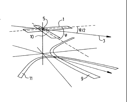
Figure 3 represents, in addition to the first antenna 1 (oriented as in
5 figure 2), the second antenna 10, symmetrical with the antenna 1 relative
to
the axis 3. As mentioned above, these two antennas form between them an
angle 9 that is preferably equal to 90 C. It will be noted that, if the
sounder
comprises more than two antennas, the angle 9 may be different from 900
and the additional antennas are advantageously receive antennas that are
preferably either perpendicular to the route of the platform, or perpendicular
to the two transmit antennas. In the first case, the system comprises, in
addition to the two transmit antennas, a single receive antenna, optionally
under-sampled, as explained above. In the second case, there are two
receive antennas associated with the two transmit antennas. The swath
produced by the antenna 10 is referenced 11.
According to another feature of the invention, the antenna 1 transmits
at a frequency f1 and receives at a frequency f2, while the antenna 10
transmits at the frequency f2 and receives at the frequency f1. The condition
to be respected for these two frequencies is that they be close enough to one
another in order to be able to be situated in the bandwidth of the two
antennas, and that they be able to be separated spectrally by the receive
devices connected to these antennas.
The value of this antenna configuration is that it combines the
advantages of the off-target aiming, the out-of-alignment and causes the two
antennas to operate at different transmit frequencies. These advantages are,
in particular:
A the longitudinal resolution is much better than that of a simple
SMF,
A the off-target aiming toward the front makes it into a
navigation instrument that is suitable for providing the safety
of the warship constituting the carrying platform,
A the slight grazing supplies a sounding similar to that of a
lateral sonar and well suited to the topographical readings,
A the out-of-alignment makes it possible to envisage
ambiguous receive antennas improving the lateral resolution,
CA 02650524 2008-10-27
6
)> The double swath makes it possible to correct very simply the
effects of the disruptions of attitude (roll, pitch and yaw).
Specifically, the correction of the movements of the platform
is necessary to provide a "gapless" coverage of the readings.
The usual configuration is totally insensitive to roll; it is
possible to virtually perfectly correct the effects of pitch; on
the other hand it is very sensitive to yaw movements. The
configuration of the invention is sensitive to the three platform
rotations (roll, pitch, yaw), but the residual error after
correction is smaller than in the worst case of the
conventional geometry. Since transmission is ambiguous, it is
not possible to correct the pointing thereof everywhere (there
is no equivalence between electronic pointing and rotation)
and it is therefore necessary to choose the corrected position,
and it is necessary to very frequently provide several
transmissions and several pointings in order to ensure the
continuity of coverage. In this instance, having two antennas
improves the situation. The principle of correction consists in
using conventional attitude measurements (carried out with
the aid of an angular station) in order to define the rotation
sustained by the antenna system and impose as the direction
of pointing of each antenna the nominal direction of the
antenna in the absence of rotation. This makes sure that, in
the front zone, the sounding is not too disrupted by the
interfering rotations (naturally these effects will make
themselves felt outside the front zone, but with consequences
that are easier to manage). It should also be pointed out that
certain manufacturers use two antennas (one on each side)
in order to improve correction, but in a configuration with two
transmit antennas that are parallel with one another and
independent.