Note: Descriptions are shown in the official language in which they were submitted.
CA 02650669 2009-01-16
APPARATUS AND METHOD FOR DETECTION OF A LEAK IN A PUMP MEMBRANE
Technical Field
The present invention relates to fluid flow control systems and more
specifically to the detection of fluid leakage in a fluid control system.
Background
Numerous devices exist in the prior art for controlling the flow of fluid. A
subclass of such devices includes fluid flow control systems. Fluid flow
control
systems regulate the rate of distribution of transport fluid through a line.
Some
examples of fluid control systems are kidney dialysis machines and intravenous
blood transfusion devices. Fluid flow control system may include a cassette
holder in which a disposable cassette is placed and wherein transport fluid is
pumped by a membrane which is part of the cassette.
FIG. 1 shows a portion of a prior art flow control system 14 which
includes a cassette 10 mounted on a cassette holder 12. A flexible membrane 11
covers the face of the flow control system cassette 10 and is permanently
attached to the cassette 10.
The flow control system 14 has a valving chamber 17 located in the
cassette 10 and a valve control volume 19 located in the cassette holder 12
which
defines a valve 50. A portion of the flexible membrane 11 separates the
valving
chamber 17 and the valve control volume 19 and acts as a barrier to keep
control
fluid in the valve control volume 19 from mixing and contaminating transport
fluid in the valving chamber 17. The control fluid is delivered to the valve
control volume 19 through a valve control fluid line 15.
The flow control system 14 has a pump chamber 18 located in the flow
control system cassette 10 and a pump control volume 100 located in the
cassette
housing 12 which defines a pump 52. A portion of the flexible membrane 11
separates the pump chamber 18 and the pump control volume 100 and acts as a
barrier to keep the control fluid in the pump control chamber 100 from mixing
and contaminating the transport fluid in the pump chamber 18 while transport
1
CA 02650669 2009-01-16
fluid is being pumped into or out of the pump chamber 18. The control fluid is
delivered to the pump control chamber 100 through a pump control fluid line
16.
One problem with such a system is the cassette membrane may become
punctured during transportation and handling of the cassette. If pinholes
develop in the cassette membrane, the transport fluid may leak into the
cassette
holder requiring the cassette holder to be cleaned and replaced. Additionally,
the control fluid may contaminate the transport fluid. The prior art system
described above did not determine if there is a leak in the cassette after it
is
mounted in the cassette holder and prior to any transport fluid being pumped
through the cassette.
Summary of the Invention
In accordance with one embodiment of the invention, a method for
detecting a leakage rate of fluid through a membrane in a fluid flow control
system is provided. The fluid flow control system has a first chamber and a
second chamber, the membrane is disposed between the first chamber and the
second chamber, the second chamber has a connection to a pressure tank, the
pressure tank has a fluid with a pressure, and the connection defines a fluid
path. The method includes in a first step, blocking the fluid path. The
pressure
of the fluid in the pressure tank is then adjusted. The pressure is measured
in
the pressure tank which creates a pressure measurement at each of a first set
of
multiple timed intervals while the fluid path is blocked and after the
pressure is
adjusted. A blocked pressure rate is calculated based on the pressure
measurements in the pressure tank at the first set of multiple timed
intervals.
Next, the fluid path is unblocked. The pressure is measured within the
pressure tank creating a pressure measurement at each of a second set of
multiple timed intervals after the fluid path is unblocked. Then, an unblocked
pressure rate is calculated based on the pressure measurements in the pressure
tank at the second set of multiple timed intervals. Finally a leakage rate is
calculated based on the blocked pressure rate and the unblocked pressure rate.
In another embodiment of the method a further step is added. An alarm
CA 02650669 2009-01-16
is caused when the leakage rate becomes greater than a predetermined
threshold value. The alarm may originate in the processor. The alarm may also
be either a visual alarm or an auditory alarm.
In a further related embodiment, in the step of measuring a pressure at a
first set of multiple timed intervals and in the step of measuring a pressure
at a
second set of multiple timed intervals the pressure is measured with a
transducer. In yet another related embodiment, in the step of calculating a
blocked pressure rate and in the step of calculating an unblocked pressure
rate,
the rates are calculated in a processor.
In yet another related embodiment, additional steps are added. After the
step of measuring the pressure at a first set of multiple timed intervals,
each of
the pressure measurements is stored in a memory unit and the pressure
measurements are then provided to the processor. Additionally, after the step
of
measuring the pressure at a second set of multiple timed intervals, each of
the
pressure measurements may be stored in the memory unit and then provided to
the processor.
In another embodiment of the invention, the embodiment is directed
toward a flow control system. The system may include a first chamber and a
second chamber with a membrane disposed between the first and second
chambers. The system further includes a pressure tank containing a fluid
having
a pressure connected to the second chamber. A transducer is disposed within
the pressure tank which creates a pressure signal. A valve is disposed between
the chamber and the pressure tank. The system also includes a valve controller
connected to the valve, a pump connected to the pressure tank and a processor
connected to the transducer, to the pump and to the valve controller.
The processor performs the following. The processor signals the valve
controller
to shut the valve. The processor adjusts the pressure of the fluid in the
pressure
tank with the pump. The pressure signal is read from the transducer at a first
set
of predetermined timed intervals and a baseline leak rate is calculated based
on
the first set of pressure signals while the valve is shut by the processor.
The
processor then sends a signal to the valve controller to open the valve. The
3
CA 02650669 2009-01-16
processor reads the pressure signal from the transducer at a second set of
predetermined timed intervals while the valve is open and calculates a
membrane leak rate based on the second set of pressure signals. A leakage rate
is calculated based on the baseline leak rate and the membrane leak rate and
an
alarm signal is created if the leakage rate exceeds a predefined value. The
alarm
signal may be an auditory or a visual alarm. In a preferred embodiment the
fluid may be air.
The system may further include a memory unit for storing the pressure
signals at the first set of predetermined timed intervals and storing the
pressure
signals at the second set of predetermined timed intervals.
A computer program product is provided, in yet another embodiment of
the invention. The computer program product is a computer usable medium
having computer readable program code thereon. The computer readable
program code includes:program code for activating a valve controller for
blocking the fluid path.
program code for adjusting the pressure of the fluid in the pressure tank;
program code for reading the pressure in the pressure tank;
program code for creating a pressure measurement at each of a first set of
multiple timed intervals while the fluid path is blocked and after the
pressure is
adjusted;
program code for calculating a blocked pressure rate based on the
pressure measurements in the pressure tank at the first set of multiple timed
intervals;
program code for activating the valve controller unblocking the fluid
path;
program code for reading the pressure within the pressure tank;
program code for creating a pressure measurement at each of a second set
of multiple timed intervals after the fluid path is unblocked;
program code for calculating an unblocked pressure rate based on the
pressure measurements in the pressure tank at the second set of multiple timed
intervals; and
4
CA 02650669 2009-01-16
program code for calculating a leakage rate based on the blocked
pressure rate and the unblocked pressure rate.
The computer program product may further include program code for
causing an alarm when the leakage rate becomes greater than a predetermined
threshold value.
Brief Description of the Drawings
The invention will be more readily understood by reference to the
following description, taken with the accompanying drawings, in which:
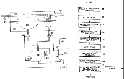
FIG. 1 is a schematic of a prior art flow control system;
FIG. 2 is a schematic of one embodiment of the invention for detecting holes
in a
fluid control system cassette; and
FIG. 3 is a block diagram illustrating a method of using one embodiment of the
invention.
Detailed Description of Specific Embodiments
An embodiment of the apparatus for the detection of a leak in a
membrane of a fluid flow control system cassette is shown in FIG 2. The
detection apparatus may be used in a fluid flow control system similar to the
fluid flow control systems described in U.S. patent 4,778,451 to Kamen and in
related patents 4;976,162, 5,088,515, and 5,178,182 all to Kamen.
In an embodiment of the apparatus, the fluid flow control system
includes a cassette holder 212 in which a cassette 200 is placed. The cassette
holder 212 may be a housing in which the cassette is enclosed or it may be a
shelf on which the cassette is mounted. In one embodiment of the apparatus
where the fluid control system is used for kidney dialysis, multiple patients
may
use the same cassette holder where each patient has their own disposable
cassette.
A transport fluid may be pumped through the cassette 200 once the
cassette 200 is connected to the cassette holder 212. In this embodiment of
the
apparatus, the cassette 200 includes at least two chambers: a pump chamber 218
and a valving chamber 217, however it is possible that the apparatus has a
single
5
CA 02650669 2009-01-16
chamber or multiple chambers. In a preferred embodiment, the cassette has a
flexible exterior membrane 211 which will deform in response to pressure from
a control fluid. This deformation of the membrane causes the transport fluid
to
be pumped.
When the cassette 200 is properly positioned with respect to the cassette
holder 212 the cassette membrane 211 is exposed to two chambers defined by
the cassette holder 212: a valve control chamber 219 and a pump control
chamber 300. In other embodiments of the apparatus, the cassette holder 212
may have a single chamber or multiple chambers. The valve control chamber
219 and the pump control chamber 300 of the cassette holder 212 align with the
pump chamber 218 and the valving chamber 217 of the cassette, respectively.
Pressure in the valve control chamber 219 and the pump control chamber 300 is
regulated by a valve control valve 221 and by a pump control valve 222. The
valve control valve 221 is controlled by a valve controller 223 and the pump
control valve 222. is controlled by a pump valve controller 229. A control
fluid
line 220 supplies a control fluid from a pressure reservoir volume 224. The
pressure reservoir volume may also be referred to as a pressure tank. The
pressure of the control fluid within the pressure tank may be increased
through
pump 240 or relieved by opening a vent valve 242. Additional valves, pumps,
chambers and pressure reservoir tanks may be incorporated into the apparatus
without changing the overall function of the fluid control system.
By alternating the opening and closing of the pump control valve 222 and
the valve control valve 221, the control fluid can be dispersed from the
pressure
reservoir volume 224 to change the pressure placed on the membrane 211 at the
pump control chamber 300 and at the valve control chamber 219. Through
alternating pressure change, the transport fluid is directed through the
cassette
200.
The system may precisely and accurately measure the volume of fluid
being transported using known methods, such as Boyle's law, as disclosed in
patent 4,808,161 or acoustic spectral analysis as disclosed in patent
5,349,852.
The pressure in the pressure
6
. . CA 02650669 2009-01716
reservoir volume 224 is measured by a pressure transducer 225. (Any
instrument for converting a fluid pressure to an electrical, hydraulic,
optical or
digital signal will be referred to as a "transducer".) The output signal from
the
pressure transducer 225 is relayed to a data processing unit 226, such as, a
microprocessor.
The data processing unit 226 has a memory unit 227 capable of storing
and retrieving data from the data processing unit 226. The data processing
unit
226 has the ability to control the operation of the valve control valve 221 by
a
valve controller 223 and the pump control valve 222 by the pump valve
controller 229 and the vent valve 242 by the vent valve controller 244. The
data
processing unit 226 also controls an alarm unit 228. The alarm unit 228 may
be,
but is not limited to, an auditory alarm or a visual alarm. The alarm unit 228
may also contain shutdown mechanisms that, when activated, prevents the use
of a damaged flow control system cassette 200.
FIG. 3 is a block diagram showing a method of using one embodiment of
the invention. The steps of the following described method are performed on
the flow control system prior to transport fluid being pumped through lines
250
and 252. The cassette 200 is in a "dry" state, such that no transport fluid
has entered
the cassette and the control fluid is not pressurized by the pump 240.
During the first step (Step 30), the data processing unit 226 will verify
that a flow control system cassette 200 is mounted on the cassette holder 212.
The flow control system has either a contact switch, or a sensor which sends a
signal to the data processing unit 226 indicating that the cassette 200 is in
the
proper position for operation of the control flow system and pumping of the
transport fluid.
If a flow control system cassette 200 is properly mounted on the cassette
holder 212, the data processing unit 226 proceeds to close valves 221, 222 and
242 (Step 32) wherein the data processing unit 226 sends a signal to the valve
controller 223 to close the valve control valve 221 and sends a signal to the
pump valve controller 229 to close the pump control valve 222 thereby
isolating
the pressure reservoir volume 224 from the valve control chamber 219 and the
7
CA 02650669 2009-01-16
pump control chamber 300. By isolating the cassette holder from the cassette,
a
baseline leak rate may be calculated for the cassette holder.
In the pressurize volume step (Step 34), the pressure reservoir volume
224 is pressurized with a control fluid. The data processing unit sends a
signal to
the pump 240 to pressurize the control fluid. In a preferred embodiment, the
control fluid is air. The pressure of the control fluid of the pressure
reservoir
volume 224 may also be decreased by creating a partial vacuum with pump 240
on the control fluid. In other embodiments, a second pressure reservoir tank
and
a control fluid valve may be incorporated into the system to provide a partial
vacuum reservoir for the system. The control fluid valve may be placed at a
position along the control fluid line 220 with the second tank attached to the
control fluid valve. The pressure of the control fluid within the second tank
may
be decreased to below atmospheric by the vacuum pump. The control fluid
valve may then be opened, decreasing the overall pressure of the control
fluid.
As in other embodiments, the data processing unit 226 controls operation of
the
vacuum pump and the control fluid valve.
In the step of recording and measuring (step 36), the signal from the
pressure transducer 225 is sent to the data processing unit 226, then
converted
into data by an analog to digital conversion. In other embodiments, the
transducer 225 may produce a digital signal where the data processing unit 226
would not perform an analog to digital conversion. A plurality of measurements
at predetermined times are saved over a sampling period and finally stored in
the memory unit 227 in digital form. In one embodiment, a first pressure
measurement is made and stored at the beginning of the sampling period and at
the end of the sampling period, a second pressure measurement is made. The
selection of the sampling period length is determined, in part, by such
factors as
the size of the pressure reservoir and the resolution of the pressure
transducer.
The larger the pressure reservoir and the higher the resolution of the
transducer
the shorter the sampling period needs to be.
In the step of determining a baseline leak rate of the system(LB) (step 38),
the data processing unit 226 first retrieves the measurement data from the
8
CA 02650669 2009-01-16
memory unit 227 and calculates a baseline leak rate by first taking the
difference
between the pressure measurement at the beginning of the sampling period and
the measurement at the end of the sampling period and dividing by the
sampling period. Other methods for determining a rate may also be
implemented, where more than two measurement values are used, such as,
determining a least-squares-fit line prior to calculating the baseline
leakrate. In
the step of opening the valve (step 40), the data processing unit 226 sends a
signal to the valve controller 223 and the pump valve controller 229 to open
the
valve control valve 221 and the pump control valve 222, respectively.
In the next step (step 42), the pressure transducer 225 produces a pressure
signal in the pressure reservoir volume 224 and sends the signal back to the
data
processing unit 226 where the signal is converted from analog to digital. The
digital data is sampled at least twice during the sampling period and the data
is
then stored in the memory unit 227. In one embodiment, a first pressure
measurement is made and stored at the beginning of the sampling period and at
the end of the sampling period, a second pressure measurement is made.
The data processing unit 226 then calculates the leak rate of the
membrane (LM) (Step 44) by first taking the difference between the pressure
measurement at the beginning of the sampling period and the measurement at
the end of the sampling period and then dividing by the sampling period. All
of
the data measurements that are used for calculating L.,1 are obtained while
the
valve control valve 221 and the pump control valve 222 are open. In other
embodiments, alternative techniques for calculating the membrane leakrate may
be used when there are more than two pressure measurements. Such techniques
are known to those skilled in the art and include calculating a least-squares-
fit
line prior to calculating the membrane leakrate.
In comparing LB and Lm (step 46), the data processing unit 226 compares
the two leak rates and determines if the difference between the leak rates is
greater than a critical leak rate. The critical leak rate is an empirically
determined value found by measuring the leak rate of the cassette with known
defects in the membrane.
9
CA 02650669 2012-01-20
If the data processing unit 226 determines that the difference between the
two leak rates is greater than the critical leak rate, the data processing
unit 226
will initiate an alarm sequence (Step 48). The alarm sequence may include
activating an auditory or visual indicator and may also include a shutdown
procedure to prevent the use of a faulty flow control system cassette 200.
Comparing the baseline leak rate for the system and the leak rate of the
membrane, allows the data processing unit to determine if the membrane has
been punctured or is defective before it is used for pumping the transport
fluid.
This provides a higher level of safety by eliminating the possibility of
contaminating the transport fluid through exposure to the control fluid.
Additionally, this system aids in the accuracy of the volumetric measurement
of
transport fluid that is delivered by stopping the fluid flow control system
from
operating when a puncture occurs which would bleed off transport fluid from
its intended destination and produce erroneous results. Additionally the
system
prevents transport fluid from flowing into the cassette holder. If transport
fluid
flows into the cassette holder, the cassette holder must be cleaned.
Although the invention has been described with reference to several
preferred embodiments, it will be understood by one of ordinary skill in the
art
that various modifications can be made without departing from
the invention described herein.
10