Note: Descriptions are shown in the official language in which they were submitted.
CA 02650714 2008-10-29
Teat for milk bottles
Technical field
The present invention relates to a teat for milk
bottles, i.e. milk bottles for infants.
Prior art
Breastfeeding is the best and most natural way to feed
a baby. Many scientific studies have shown that
breastmilk is of great importance in the development of
the baby. The immune system is stronger, and the baby
is more robust. The mechanical effect of sucking on the
breast also has a significant influence on the
development of the palate shape and of the muscles.
Unfortunately, breastfeeding is not always possible, or
in some cases it is possible only to a limited degree:
for example if the mother returns to work or is absent
when the baby wants to feed, in cases of disease, if
the nipples are sore, or if the mother has too little
milk and the baby additionally requires replacement
feed.
In these situations, the milk is pumped off and given
to the baby by bottle, spoon, beaker or finger.
Unfortunately, the teats available today have negative
effects on breastfeeding. The problems lie in the fact
that the baby has to learn the technique of suckling at
the breast. When it has become used to this and then
has to drink from a bottle, it initially sucks from the
latter in the same way as from the breast. The baby
then notices that the teat behaves differently and that
the ratio between vacuum and milk flow is different.
Likewise, the peristaltic movement of the tongue cannot
be performed to the same extent. In many conventional
teats, the baby has to stop the flow of milk with its
tongue instead of with the reduction in the vacuum.
CA 02650714 2008-10-29
- 2 -
Most teats are hollow on the inside and have holes or
slits at the outlet. However, the diameters of the
holes at the outlet are very rarely the optimum
diameters: the passages are either too large or too
small. Moreover, teats that are hollow on the inside do
not have the correct elasticity. They are often too
soft or too hard. Another weak point of the teats
available today is that, during the sucking phase,
practically no lengthening of the mouthpiece takes
place.
A crucial factor during sucking is the interface
between the baby's lips and the areola in terms of lip
support. In conventional teats, the lips are not
supported in a natural way because the teats, in the
area of the lip support, do not participate in the
function and because they are hollow and have too
little elasticity.
It is true that teats with valves have been developed
(see EP 1 416 900 51, US 2004/144744, US 5 035 340).
There are also patents for teats with capillaries (see
patent MXPA 05004972 or US 6588613) which are intended
to better simulate the natural function. Unfortunately,
these systems have various disadvantages in use and are
especially difficult to manufacture. Moreover, cleaning
is difficult, which leads to disadvantages in terms of
hygiene.
WO 03/013419 discloses a teat for a milk bottle with an
inner part and outer part, wherein both parts are
designed as flexible membranes that between them form a
chamber. The inner part is provided with a valve, which
controls the flow of milk from the bottle into the
chamber. At its tip, the outer part has an opening
through which the baby can suck the milk out of the
chamber. The two parts are configured such that, when
the outer part is pressed together or sucked, the valve
CA 02650714 2008-10-29
3 -
is closed, and, when the outer part is released, the
valve is opened.
WO 02/22073 discloses a two-part teat for a feeding
cup, the inner part in this case acting as valve. In
the rest state, the inner part is spring-loaded upward
so as to press against the opening of the outer part,
such that the teat is leaktight. If pressure is
exerted, the inner part drops down and frees the
opening of the outer part. If the outer part is now
pressed together, it bears tightly on the side walls of
the inner part, whereas in the released state it frees
the through-channels to the cup.
BE 381523 describes a feeding bottle with a teat, and
with a plate arranged between bottle and teat. This
plate has capillaries in order to regulate the flow of
milk.
GB 2 370 787 discloses a feeding bottle with a valve
that is arranged in the teat and that is intended to
regulate the flow of milk.
In the teats available today, the natural function of
breastfeeding as a whole is not simulated. Individual
aspects of the natural function are met by various
suppliers, but there is as yet no product available
that simulates all the aspects of breastfeeding to a
satisfactory extent.
Because of the many weaknesses, a natural feeding
action when drinking from the milk bottle is not really
possible with the conventional teats. The baby is
irritated by these shortcomings and becomes used to
sucking the wrong way, which has a negative impact on
the natural breastfeeding. Advisers on breastfeeding
describe this as "nipple confusion".
CA 02650714 2008-10-29
4 -
Disclosure of the invention
It is therefore an object of the invention to make
available a teat that simulates the sucking action on
the human breast as closely as possible.
This object is achieved by a teat that has the features
of claim 1 or of claims 18 and 19.
The teat according to the invention for breastmilk
bottles has a receiving head made of a dimensionally
stable material, and a suction body made of a rubber-
elastic material. The receiving head is designed as the
core of the teat, and the suction body can be pushed on
over the receiving head. The receiving head is provided
with an admission channel leading to the interior of
the bottle, and with at least one channel leading from
this to the outer surface of the receiving head. The
suction body has a mouthpiece and, extending within the
latter, an outlet channel for milk, such that, when an
underpressure is generated in the mouthpiece, milk can
flow from the milk bottle into the outlet channel. The
suction body, in an initial position, bears elastically
and sealingly with an inner surface on at least one
portion of an outer surface of the receiving head. In
this contact area between the suction body and the
receiving head, milk channels are present which
communicate with the at least one channel of the
receiving head and lead toward the outlet channel in
the mouthpiece such that, when an underpressure is
generated in the mouthpiece, milk can flow from the
milk bottle through the milk channels into the outlet
channel, the suction body being able to return to its
initial position and the flow of milk being interrupted
when there is no underpressure.
CA 02650714 2008-10-29
- 5 -
The milk channels are preferably arranged in the inner
surface of the suction body and/or in the outer surface
of the receiving head, and they are in each case open
toward the other surface.
The milk channels are preferably designed as
capillaries. Capillaries are understood as narrow
channels in which surface forces are active such that,
without a vacuum being generated, there is no flow of
milk.
In another embodiment of the invention, the teat for
milk bottles has a receiving head made of a
dimensionally stable material, and a suction body made
of a rubber-elastic material, wherein the receiving
head is designed as the core of the teat, and the
suction body can be pushed on over the receiving head,
wherein the suction body has a mouthpiece and,
extending within the latter, an outlet channel for
milk, such that, when an underpressure is generated in
the mouthpiece, milk can flow from the milk bottle into
the outlet channel, wherein the suction body, in an
initial position, bears elastically and sealingly with
an inner surface on at least one portion of an outer
surface of the receiving head. This teat is
characterized by capillary milk channels which are
present in this contact area between the suction body
and the receiving head and which lead toward the outlet
channel in the mouthpiece such that, when an
underpressure is generated in the mouthpiece, milk can
flow from the milk bottle through the milk channels
into the outlet channel, the suction body being able to
return to its initial position and the flow of milk
being interrupted when there is no underpressure.
In another embodiment of the invention, the teat for
milk bottles has a receiving head made of a
dimensionally stable material, and a suction body made
CA 02650714 2008-10-29
- 6 -
of a rubber-elastic material, wherein the receiving
head is designed as the core of the teat, and the
suction body can be pushed on over the receiving head,
wherein the suction body has a mouthpiece and,
extending within the latter, an outlet channel for
milk, such that, when an underpressure is generated in
the mouthpiece, milk can flow from the milk bottle into
the outlet channel, wherein the suction body, in an
initial position, bears elastically and sealingly with
an inner surface on at least one portion of an outer
surface of the receiving head, and wherein an admission
channel leading to the interior of the bottle is
provided in the receiving head. This teat is
characterized by at least one channel which is provided
in the receiving head and which leads from the
admission channel to the outer surface of the receiving
head in the contact area of the suction body, such
that, when an underpressure is generated in the
mouthpiece, milk can flow from the milk bottle through
the milk channels into the outlet channel, the suction
body being able to return to its initial position and
the flow of milk being interrupted when there is no
underpressure.
The function is essentially the same as in normal
breastfeeding from the human breast. By means of the
baby sucking on the teat, or on the tip thereof, a
vacuum is generated and milk is conveyed out of the
bottle, between the outer surface of the receiving head
and the inner wall of the suction body, through to the
outlet.
The natural sucking action consists basically of the
following functions and parameters: sucking strength,
sucking rhythm, tongue movement, support of the lips,
and pressure on the nipple and areola. The teat
according to the invention now provides an overall
system which simulates all the main functions and
CA 02650714 2008-10-29
- 7 -
parameters of breastfeeding. For example, if no vacuum
or pressure is generated by the baby (by means of the
lips or tongue), no milk is released. If the teat is
pressed together, without a vacuum being generated,
again there is no release of milk. Only when a vacuum
and pressure on the teat are generated does the milk
flow. The quantity of milk can thus be controlled by
the vacuum, the suction rhythm and the pressure of the
tongue and lips.
The teat feels soft and flexible. It is preferably made
of an elastic solid material that extends in the
longitudinal direction under vacuum, similarly to the
nipple. The lip support is adaptable and elastic.
By virtue of the teat according to the invention, the
vacuum/milk flow ratio is comparable to the milk flow
of the human breast.
The teat according to the invention is also inexpensive
to produce and can be optimally cleaned.
By means of the sucking on the mouthpiece and the
peristaltic movement of the tongue, a vacuum is
generated. As the vacuum builds up, and as a result of
the tongue movement, the mouthpiece is deformed and
axially lengthened. In addition, the lip support is
deformed, such that the teat in the baby's mouth is
sucked in far in the direction of the palate. By means
of this movement, the suction body in the area of the
milk channel closure wall lifts from the receiving head
and opens the passage to the outlet channel. The milk
thus flows out of the bottle through any milk channels
and any milk chambers to the outlet channel. The milk
channels lie between the outer surface of the receiving
head and the inner wall of the suction body. The
purpose of the milk channels is to allow the milk to be
dispensed from the bottle in doses according to the
CA 02650714 2008-10-29
- 8 -
sucking action of the baby. The milk flow in relation
to the vacuum is determined by the capillary cross
sections and capillary lengths. The milk chambers allow
the mother in particular to visually check that there
is no air in the system, since care should be taken to
ensure that the baby does not swallow any air while
drinking. The milk chambers are thus optional.
In a preferred embodiment, the actual suction body is
composed of a soft elastic outer part of silicone and a
harder inner part of silicone, which parts are
preferably produced in a multi-component injection
molding technique and are connected to each other in a
non-detachable manner. The outer soft part of the
suction body can preferably feel like, and deform in
the same way as, the nipple and the areola. The inner
harder part of the two-component silicone suction body
gives the suction body the required stability. In
addition to this stabilizing function, the inner part
of the suction body also provides protection against
the latter possibly being bitten through in the area of
the elastic mouthpiece. The inner part is designed as a
cylindrical tube in the area of the mouthpiece.
Protection against biting through can also be provided
by other geometric shapes or materials, for example a
spiral or a fabric insert.
As has already been mentioned, the flow speed depends
on the vacuum. At a low vacuum, there is minimal flow
of milk, while at a higher vacuum the flow is
correspondingly greater. Regardless of which vacuum
suction curve the baby defines, the system adapts.
Thus, for example, a baby may keep the vacuum at a high
level over a long time and the milk flows constantly.
As soon as the vacuum is reduced, the flow of milk also
reduces. If no vacuum is applied to the teat between
the sucking phases, the suction body bears on the milk
channel closure wall and closes the outlet. The teat
CA 02650714 2008-10-29
- 9 -
system thus adapts in each phase to the sucking action
of the baby, regardless of how long the baby maintains
the vacuum. The milk is released in accordance with the
sucking action.
With the present invention, natural breastfeeding can
be further enhanced since the baby is not confused by
the teat and there is therefore no longer a danger of
the breastfeeding being ended too early.
Particularly advantageous embodiments of the invention
are set forth in the dependent claims. The features of
the dependent claims can refer equally to claim 1 and
to claims 18 and 19.
Brief description of the drawings
The invention is explained in more detail below with
reference to the illustrative embodiments depicted in
the drawings, in which:
Figure 1 shows the basic structure of a teat according
to the invention fitted on a milk bottle, in
a purely schematic cross section and
according to a first embodiment;
Figure 2 shows, likewise in cross section, the
receiving head (suction body receiver) with
integrated threaded flange according to
Figure 1;
Figures 1* and 2*
show a view of a second embodiment of teat
and receiving head, respectively;
Figure 3 shows an exploded view of a third embodiment
of the teat according to the invention
together with bottle;
CA 02650714 2008-10-29
- 10 -
Figures 3b to 3d
show, purely schematically, variants of a
receiving head part according to Figure 3;
Figure 4 shows the suction body according to Figure 1*
in cross section;
Figure 5 shows the teat according to Figure 3a in the
assembled state;
Figure 5a shows the suction body according to Figure 3a
in a perspective view from underneath;
Figure 5b shows an exploded view of suction body and
receiving head according to Figure 3a, with a
view of the suction body from underneath;
Figures 6a to 6d
show a longitudinal section through a suction
body according to the invention in further
embodiments;
Figure 7 shows a greatly enlarged detail, between
suction body and receiving head, of the vent
to the bottle interior;
Figure 8 shows a longitudinal section through the teat
according to the invention in a further
embodiment;
Figure 9 shows a teat in the initial position (without
vacuum);
Figure 10 shows a teat during the sucking phase, and
CA 02650714 2008-10-29
- ~1 -
Figure 11 shows a suction body according to the
invention with a safety device according to a
further embodiment.
Ways of implementing the invention
The invention described below relates to a teat for
milk bottles or a drinking system for feeding infants.
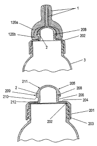
As is shown schematically in Figures 1 and 1*, the
system is composed of a suction body 1 made of rubber-
elastic material, e.g. of silicone, and a dimensionally
stable or dimensionally rigid distributor head or
receiving head 2 which forms a receiver for the suction
body 1 and which is here provided with an integrated
threaded flange or threaded ring 203 for screwing the
receiving head 2 onto a milk bottle 3 in a detachable
manner. The receiving head 2 is preferably made from a
rigid plastic in an injection molding technique. For
example, it is made from hard plastic.
The parts 1, 2, 2' described above form the teat
according to the invention. A sealing ring 202 lying
between teat and bottle 3 can be integrated as a
separate part into the receiving head 2 or can be
designed separately. It can in particular be designed
as a multi-component injection molding part.
The suction body 1 preferably has an outer shape
corresponding to the known teats and simulating the
nipple of a human breast. It has a teat, here in the
form of a tubular mouthpiece 117 with a milk outlet
123, which mouthpiece 117 widens toward a lip support
119 (see Figure 4). The teat can be designed
eccentrically.
The suction body 1 is preferably designed with a thick
wall, i.e. it is substantially not hollow, except for a
CA 02650714 2008-10-29
- 12 -
recess that is to be pushed on over the receiving head
2. The recess is dimensioned such that the suction body
1 in the rest state, i.e. without external
underpressure, bears sealingly on the receiving head 2.
From said recess, a milk outlet channel 106 leads to
the milk outlet 123 at the outer tip of the suction
body 1.
The suction body 1 can be designed in one piece, as is
shown in Figure 1. However, it can also be designed in
several pieces, in particular in two parts, as is shown
in Figure 1*. Here, the suction body 1 is composed of
an outer part 120a and an inner part 120b. The inner
part 120b and the outer part 120a are connected to each
other in a non-detachable manner. The suction body 1 is
preferably produced in a multi-component injection
molding technique. The suction body 1 can also be
produced from more than two materials or from only one
material.
The outer part 120a of the suction body is made of a
soft material. The mouthpiece 117 and lip support 119
in particular should correspond as far as possible to
the shape and firmness of a nipple. The outer part 120a
of the suction body 1, in the transition area between
the lip support 119 and the mouthpiece 117, preferably
has a thicker wall than the mouthpiece 117, such that
this sensitive and fragile area is strengthened.
Figures 2 and 2* show the distributor head or receiving
head 2. The head 2 is used to receive and position the
suction body 1 and to transfer milk into the suction
body 1. It has substantially the shape of a screw-on
cap for a bottle, having a threaded collar 203 with
inner thread 201, and a distributor head or head part
205 formed integrally on the cap. The cap has a cover
surface or support surface 204 closing the threaded
ring or threaded collar 203. Extending upward from this
CA 02650714 2008-10-29
- 13 -
support surface 204 are a neck or a cylindrical part
206, and the abovementioned head part 205, which here
has a substantially spherical shape. Its outer wall or
outer surface is indicated by reference number 211. In
this example, it serves as a milk channel closure wall.
The transition from the neck 206 to the head part 205
forms a sealing surface 210. The neck itself, with its
cylinder wall, can also form a cylinder seal.
As is shown in Figures 3a to 3d, the receiving head
part 205 preferably has the shape of a rotation body,
in particular the shape of a sphere, a flattened
sphere, a cone, a droplet, a cylinder, or a combination
of these shapes. Other shapes are possible.
In the receiving head 2, there is a connection channel
or admission channel 207, which leads to the interior
of the bottle and which, via at least one distributor
channel or connection channel 208, leads to the outer
surface of the receiving head 2, at least one opening
or channel being present.
A large number of connection channels 208 and therefore
outlets can be provided. The connection channels 208
preferably open into at least one distributor outlet or
distributor channel 209, which is preferably designed
as an annular channel on the outer surface of the
receiving head part 205. The distributor channel 209
preferably extends at a constant height around the head
part 205. It is also possible, however, for several
channels to be arranged above one another.
A vent hole 212 connects the interior of the bottle to
the vent valve 102, which is shown in Figure 4. This
can be done, for example, via an admission channel 207
of the receiving head 2, or directly.
CA 02650714 2008-10-29
- 14 -
The suction body 1, in Figure 1* the rubber-elastic
inner part 120b, is pushed on over the receiving head
part 205. In the state when thus fitted, the suction
body 1, as shown in Figures 1 and 1*, now bears against
the support surface 204, the cylindrical part 206 and
the outer surface or wall 211 of the receiving head
part 205. It is at these surfaces that the suction body
1 is sealed and fixed. The recess of the suction body
1, or its inner wall, defines a sealing surface 115,
which is shown in particular in Figure 4. This sealing
surface 115 is substantially spherical, or adapted to
the shape of the receiving head part 205, and narrows
downward in the direction of the bottle neck. It merges
into a holding surface 106, which extends approximately
perpendicular to the longitudinal axis of the suction
body 1 in the form of a parapet, and this is followed
by a narrowing in the form of a cylindrical neck, which
forms a cylinder seal 105. The recess then widens again
and extends obliquely outward in cross section. Said
vent valve 102 is arranged in the form of a
circumferential lip in this area.
The underside of the suction body 1 preferably has a
flattened shape and forms a bearing surface 101. The
supporting and positioning with respect to the
receiving head 2 or the teat receiver are effected via
this bearing surface 101, the cylinder seal 105 and the
holding surface 106.
The milk flows out of the bottle 3 to the suction body
1 by way of the connection channel 208. Capillary milk
channels 114 (described below) of the teat communicate
with the distributor channel 209. As is shown below,
the milk channels 114 open to the inside, and any milk
chambers 109 provided, are closed by the outer wall or
outer surface 211 of the receiving head part 205.
CA 02650714 2008-10-29
- 15 -
These milk channels 114 and milk chambers 109 are
described in more detail with reference to Figures 4
and S. In the illustrative embodiment described here,
they are integrated in the inner wall, or sealing
surface 115, of the suction body. However, they could
also be arranged completely or partially in the outer
wall of the receiving head 2, in particular of the head
part 205. The receiving head 2 and/or suction body 1
can also be formed without milk channels 114 or
capillaries and be used only as a pure valve function
in connection with a vacuum.
The milk channels 114 and milk chambers 109 are
preferably distributed uniformly about the
circumference of the recess of the suction body 1. They
preferably extend along the dome-shaped recess or inner
face 115 from a lower area, which in the mounted state
extends preferably approximately to or completely to
the annular channel 209 of the receiving head 2, to a
milk collection channel or milk outlet channel 116,
into which they preferably open, or in the area of
which they end. The milk channels 115 preferably end
above the annular channel 209 and below the outlet
channel 116.
The milk chambers 109 can be arranged at the start of,
at the end of, or at any desired location within, a
milk channel 114. Each milk channel 114, or only some
of them, can be provided with one or more milk chambers
109, or indeed none of them.
The channels 114 and milk chambers 109 can have
different shapes. The chambers 109 preferably form
pockets. For example, the channels 114 and the chambers
109 can be rectilinear, curved or thread-shaped, as is
shown in Figures 5, 5a, 5b and 6a to 6d. They can
extend in isolation or be connected to one another via
other channels. Likewise, some or all of the channels
CA 02650714 2008-10-29
- 16 -
114 can be integrated in the receiving head 2,
particularly in the receiving head part 205, instead of
in the suction body 1. The total cross-sectional
surface area of all the milk channels 114 differs in
size for use by infants of different ages.
The milk channels 114 and milk chambers 109 are open to
one side in the longitudinal direction of the teat,
i.e. they are only depressions or grooves in the
suction body 1 and, without a mating piece, i.e.
without the receiving head 2, they do not form closed
channels. These openings are present for production
reasons and are closed by the outer surface 211 of the
receiving head part 205 acting as milk channel closure
wall.
The milk channels 114 form capillaries through which
milk flows under vacuum. The geometric shape, the width
and the depth, combined with the correct Shore hardness
of the rubber, permit natural sucking and milk flow as
with the mother's breast.
The milk chambers 109 serve in particular as a means of
visually checking that the milk flow is free of air.
The sealing surface 115 of the suction body 1 serves,
on the one hand, to separate and seal off the milk
channels 114 and milk chambers 109 from one another,
and, on the other hand, as a closure between the
admission channel 207, or milk supply channel, and the
outlet channel 116. The outlet channel 116 collects the
milk from the milk channels 114 and conveys it to the
milk outlet 123. The outlet channel 116 here comprises
at least one channel.
As is shown in Figures 9 and 10, the tip of the nipple
is drawn into the mouth by the sucking function and is
pressed together. The mouthpiece lengthens and, as a
CA 02650714 2008-10-29
- 17 -
result of the deformation of the lip support 119, the
mouthpiece reaches far into the baby's mouth. As a
result of the axial movement of the mouthpiece 117, the
sealing surface 115 of the suction body 1 lifts from
the milk channel closure wall 211, i.e. the outer
surface of the receiving head 2, and thus applies a
vacuum to the milk channels 114. The greater the vacuum
produced, the more the flow of milk is promoted. As
soon as the baby reduces the vacuum, the teat moves
back to the initial position and interrupts the flow of
milk. Figure 9 shows the closed milk passage or closed
valve, when no vacuum is present and there is therefore
no flow of milk. Figure 10 shows the open milk passage
or opened valve during the sucking phase.
As can be seen in Figure 7, the interior of the bottle
is vented by the vent sealing lip 102, which allows
outside air to flow in when there is an underpressure
in the bottle 3. The air flows through air admission
opening 104 to the vent sealing lip 102. The vent
sealing lip 102 allows the air to flow only in one
direction. An opening between vent sealing lip 102 and
vent hole 212 connects the interior of the bottle to
the teat, such that an underpressure in the bottle
allows air to flow into the bottle.
At a possible overpressure in the bottle 3, the vent
sealing lip 102 is pressed onto the support surface 204
and prevents air or liquid from flowing out.
Figure 8 shows a variant of the receiving head 2. Here,
the receiving head part 205 and the threaded ring 203
are formed as two pieces. The threaded ring 203
corresponds more or less to the known threaded rings
for feeding bottles. The suction body 1 is guided via
this threaded ring 203 and is held by it on the bottle.
The receiving head part 205 is pushed into the recess
of the suction body 1 and held therein with a form fit.
CA 02650714 2008-10-29
- 18 -
In a preferred embodiment, as shown in Figure 11, a
safety device is also provided, which forms an
important functional unit. It serves to avoid any
defect that could cause injury to the baby. A defined
weak point is built in which, after a certain degree of
ageing, or after a certain period of use, is intended
to tear, such that the mother is made aware of the
defect before part of the teat comes loose and the baby
has the chance to swallow this detached part or gets it
stuck in his or her throat.
In this example, the safety device is composed of a
predetermined tear area 118, which is arranged in the
suction body 1 in the area of transition from the
mouthpiece 117 to the lip support 119. This area is the
part of the teat that is moved the most.
At this predetermined tear area 118, there is a defined
wall thickness reduction on one side of the suction
body 1, such that, after a certain degree of ageing,
the teat does not tear entirely, but instead a leak
occurs only on one side. In combination with this, the
teat can be weakened on one side by eccentric or offset
arrangement of the outlet channel 116. In this way, the
predetermined tear area 118 is further supported. It is
thus possible to avoid part of the teat coming loose
and being swallowed. Instead, the teat starts to tear
at a certain location or begins to leak.
This predetermined tear area 118 can also be used in
other teats, in particular the conventional hollow
teats.
The teat according to the invention permits a sucking
action that is as natural as possible.
CA 02650714 2008-10-29
- 19 -
List of reference numbers
1 suction body
101 bearing surface
102 vent sealing lip
104 air admission opening
105 cylinder seal
106 holding surface
109 milk chambers
114 milk channels (capillaries)
115 sealing surface
116 outlet channel
117 mouthpiece
118 predetermined tear area
119 lip support
120a outer part of suction body
120b inner part of suction body
123 milk outlet
2 receiving head
201 thread
202 sealing ring
203 threaded ring, threaded collar
204 support surface
205 receiving head
206 cylinder seal (wall surface)
207 admission channel
208 connection channel
209 distributor channel
210 sealing surface
211 milk channel closure wall or outer surface of
head
212 vent hole
3 bottle