Note: Descriptions are shown in the official language in which they were submitted.
CA 02650759 2011-01-28
1
Roller and tape-based fluid sample testing device
The present invention refers to a sample fluid testing device and a method for
analyzing a
sample fluid, using a test media tape.
Sample fluid testing devices are used e.g. by diabetics for regularly testing
samples of their
blood to determine the level of blood glucose. In one known type of fluid
testing devices,
disposable test strips are used to test the sample fluid, each test strip
comprising a sensor
field, which contains a reagent material that will react with an analyte
within the sample
fluid. One possibility well-known in the art for analyzing the sample fluid on
the sensor
field is an electrochemical analysis. For the electrochemical analysis,
electrical signals
produced within the sensor field which contains the sample fluid are relayed
from electrodes
within the sensor field to a meter via electrically conductive tracks, the
meter being part of
the sample fluid testing device. After the measurement has been taken, the
test strip is
disposed of.
Other known types of fluid testing devices contain test media cassettes with a
plurality of
sensor fields on a test media tape, the test media tape being provided on a
reel within the
test media cassette.
WO 2004/056269 Al is directed towards a body fluid testing device for
analyzing a body
fluid, comprising: a test media tape adapted to collect the body fluid, said
test media tape
comprising a tape and test media portions, wherein a free tape portion without
test medium
is located between successive test media portions. The testing device further
comprises a
supply portion, which comprises a housing in which an uncontaminated test
media tape is
contained, the housing further having an opening for withdrawing the test
media tape from
the housing. The supply portion further has a sealing means for closing the
opening against
the surrounding. A free tape portion of the test media tape is located between
a surface
(typically a wall of the housing) and the sealing means when the sealing means
closes the
opening.
EP 1 424 040 Al relates to a body fluid testing device for analyzing a body
fluid,
comprising: a test media tape adapted to collect the body fluid, a supply
portion storing an
CA 02650759 2008-10-28
WO 2007/125121 PCT/EP2007/054213
2
uncontaminated section of the test media tape, a storage portion for storing a
contaminated
section of the test media tape, an exposure portion positioned between the
supply portion
and the storage portion, the exposure portion being adapted to expose a
section of the test
media tape to the body fluid. The exposure portion has a tip portion for
exposing a test
medium to body fluid application.
For electrochemically analyzing a sample fluid on such a test media tape, an
electrical
contact from a meter within the sample fluid testing device to the sensor
fields on the test
media tape has to be established. One known solution for establishing this
contact is e.g.
described in WO 01/23885 Al. This document refers to a test device for testing
of analyte
concentration in a fluid to be applied thereto, the device comprising a
plurality of sensors
on a reel, each of the sensors carrying reagent means for producing an
electrical signal in
response to the concentration of analyte in an applied fluid. Each of these
sensors has a
plurality of electrodes, corresponding electrodes of adjacent sensors being
connected
together by a conductive track on the reel. The device further comprises a
meter with
electronic means for producing a signal output which is dependent on the
electrical signal
from the sensors. The meter has contacts, which are electrically connected
with the
conductive tracks. In this test device, all the sensors are connected by the
conductive track,
the meter also being permanently connected to the conductive track. The
application of a
sample fluid to any of the sensors will produce an electrical signal, which is
detectable by
the meter. A used sensor can be separated from the end of the reel, before a
subsequent
measurement is taken in order to prevent the generation of electrical signals
by the used
sensor during the subsequent measurement.
Another example for a sample fluid testing device with such a solution for the
electrical
contact between the sensor fields and the meter is described in US
2005/0230253 Al.
One disadvantage of this solution is that the long conductive track connecting
the
electrodes of adjacent sensors has a high resistance, which above all is
altered, when the
individual sensors are separated from the reel. Furthermore, the unused
sensors are not
totally passive and can produce interfering signals, which are not related to
the analyzed
sample fluid. Moreover, the separated sensors are contaminated with the sample
fluid and
have to be safely discarded, whereas a continuous test media tape, from which
the used
sensors are not separated, could be stored conveniently on a reel within a
waste portion of
the test media cassette.
CA 02650759 2008-10-28
WO 2007/125121 PCT/EP2007/054213
3
US 5,395,504 A therefore proposes a test media tape with a plurality of
separately arranged
sensors, which are contacted successively. The contact of each sensor with an
electronic
circuit is provided by means of resilient foils coming into contact with zones
of contact of
the sensor by means of a slide connection. One drawback of a slide connection
is, that the
sliding of the slide contacts over the surface of the moving test media tape
when the next
sensor is to be used can damage the elements on the surface of the test media
tape, e.g.
electrodes or conductive tracks made of very thin metal layers (approximately
50 nm).
WO 2005/047861 A2 discloses a biochemical analysis instrument for multiple
fluid
analysis including a housing, a sensor for sensing a reaction disposed in the
housing, an
aperture formed in the housing and a test tape housing area formed in the
housing. The
sensor is disposed to selectively move within the housing area, the aperture
being formed
to provide access to this tape housing area. The instrument further includes a
cassette
configured to be received within the tape housing area. The cassette includes
a case, a first
chamber formed in the case, a second chamber formed in the case, a gap formed
in the
case, wherein the first chamber and the second chamber are disposed at a
respective side of
the gap. A test tape is disposed within the housing, which extends from the
first chamber
across the gap to the second chamber, the test tape having a plurality of
active zones
disposed at predetermined spaced intervals along the tape for testing an
analyte. An
electrode based sensor head can be moved forward to contact the test tape and
retracted
into its original lower non-contact position. Such a solution for contacting
the sensors
requires a complex construction of the sample fluid testing device to enable
the movement
of the sensor head and the test tape and to detect their relative positions.
The present invention is therefore based on the object of avoiding the
disadvantages of the
prior art and especially of presenting a sample fluid testing device, which
allows a safe and
easy establishment of an electrical contact of a meter with the electrodes
within a sensor
field on a test media tape.
These objects are achieved by a sample fluid testing device for analyzing a
sample fluid,
comprising a test media tape comprising a tape and plurality of test media
portions. Each
test media portion contains a sensor field for producing electrical signals
when the sample
fluid is applied. The test media portions further contain at least two
electrodes, the at least
two electrodes being positioned in the sensor field and being electrically
connected to at
least two contact fields on the test media portion. The sample fluid testing
device further
comprises at least one roller with a surface which contains at least one
contact zone. The at
least one roller is in rolling engagement with the test media tape with its
surface in order to
CA 02650759 2008-10-28
WO 2007/125121 PCT/EP2007/054213
4
successively electrically contact the test media portions via at least one
contact field with
the at least one contact zone. The at least one contact zone on the at least
one roller is
electrically connected to a meter for measuring the electrical signals.
The sample fluid testing device can be provided for analyzing sample fluids
selected from
the group of body fluids, environmental samples, food samples or the like.
Preferably, the
sample fluid testing device according to the invention determines the
concentration of
glucose in blood samples.
The sample fluid testing device comprises a test media tape. This test media
tape contains a
tape, which is an elongate band used as a carrier for the test media portions.
Preferably, the
tape is made of an electrically insulating, non hygroscopic material, e.g.
plastic foils from
polyester, polycarbonate, cellulose derivatives and polystyrene. The test
media portions of
the test media tape are separate testing elements, which are arranged
successively and
preferably spaced to one another on the tape. They can be produced in the form
of labels,
which are fixed to the tape by an adhesive layer. Preferably, a free tape
portion is located
between successive test media portions of the test media tape. The test media
portions each
contain a sensor field, which may contain a reagent material and in which the
sample fluid
is analyzed electrochemically. For this purpose, each sensor field contains at
least two
electrodes. The at least two electrodes are electrically connected to at least
two contact
fields, which are also arranged on the test media portion. The contact fields
are provided
for electrically contacting the electrodes of the sensor field with connecting
elements of a
meter for measuring electrical signals produced in the sensor field. According
to the
present invention, the sample fluid testing device comprises at least one
roller for
establishing the electrical contact between the contact fields and the meter.
The surface of
this roller (which is preferably cylindrical) contains at least one
(electrically conducting)
contact zone. This contact zone is preferably surrounded by insulating
material on the
surface of the roller. The at least one roller is in rolling engagement with
the test media
tape with its surface. Preferably, the roller rolls along the surface of the
test media tape in a
longitudinal direction when the test media tape is moved to its next testing
position, in
which the sample fluid can be applied to the next media portion, while the
roller does not
change its position within the sample fluid testing device. The roller is
arranged to
electrically contact successively the test media portions via their contact
fields, when the at
least one contact zone of the roller meets a contact field on the test media
tape surface. By
establishing this contact, electrical signals produced in the sensor field can
be conducted
from the electrodes via the contact field and the contact zone to a meter for
measuring
these signals, the contact zone of the roller being electrically connected to
the meter. The
CA 02650759 2008-10-28
WO 2007/125121 PCT/EP2007/054213
meter preferably contains means for evaluating the measured electrical
signals, e.g. to
determine the concentration of an analyte within the sample fluid, and means
for
displaying an analysis result to the user of the sample fluid testing device.
5 The present invention further refers to a method for analyzing a sample
fluid, wherein the
sample fluid is analyzed on a test media tape, the test media tape comprising
a plurality of
test media portions, each test media portion containing a sensor field for
producing
electrical signals when the sample fluid is applied and at least two
electrodes. The at least
two electrodes are positioned in the sensor field and are electrically
connected to at least
one contact field of the test media portion. The method comprises the steps of
applying a
sample fluid to the sensor field of a test media portion and of rolling at
least one roller with
a surface, which contains at least one contact zone, along the test media
tape, in order to
electrically contact the contact fields of the test media portion with the at
least one contact
zone. Furthermore, it comprises measuring the electrical signal produced
within the sensor
field with a meter, which is electrically connected to the at least one
contact zone of the
roller. This method is preferably carried out using a sample fluid testing
device according
to the present invention. The analyzed sample fluid is preferably selected
from the group of
body fluid, environmental sample and food sample. The order of applying the
sample fluid
and electrically contacting the contact fields by means of the roller can be
freely chosen.
The present invention further refers to a method for preparing a sample fluid
testing device
for analyzing a sample fluid, wherein the sample fluid is analyzed on a test
media tape, the
test media tape comprising a plurality of test media portions, each test media
portion
containing a sensor field for producing electrical signals, when the sample
fluid is applied,
and at least two electrodes, the at least two electrodes being positioned in
the sensor field
and being electrically connected to at least two contact fields of the test
media portion.
According to this method, at least one roller is rolled with its surface,
which contains at
least one contact zone, along the test media tape, in order to electrically
contact the contact
fields of the test media portion with the at least one contact zone, which is
electrically
connected to a meter. When this contact is established, the sample fluid
testing device is
prepared to analyze a sample fluid electrochemically in the sensor field of
the contacted
test media portion.
One advantage of the device and the method according to the present invention
is, that an
electrical contact between a meter and an individual test media portion of a
test media tape
can be established without scratching over the surface of the test media tape
and without a
CA 02650759 2008-10-28
WO 2007/125121 PCT/EP2007/054213
6
complicated mechanism for placing an electrical contact element exactly on the
contact
fields of the test media portion.
According to a preferred embodiment of the present invention, the at least one
contact zone
of the at least one roller is electrically connected to the meter by a sliding
contact. Thereby,
the functions of contacting the contact fields on the movable test media tape
and of
connecting the rotatable roller to the immobile meter are separated.
According to a preferred embodiment of the present invention, the at least one
contact zone
is an electrically conducting annular zone arranged on the circumference of
the surface of
the roller. Such a roller can be produced by stacking alternately round discs
of a
conducting material and round discs of an insulating material and joining them
to form a
cylindrical roller. The round discs of conducting material will then form
annular contact
zones on the surface of the roller, flanked by annular non conducting zones
formed by the
discs of insulating material. The contact zones of the roller can also be
produced by coating
selected zones (e.g. annular zones) on the surface of a roller with a
conducting material
(e.g. a metal), the roller consisting of an insulating material.
In the sample fluid testing device according to the invention, the contact
fields can be
arranged in at least two rows on the test media portion, the rows being
arranged in a
transverse direction of the test media tape and the contact fields within two
different rows
being shifted to one another in the transverse direction. This arrangement is
especially
favourable if a plurality of contact fields is required for each test media
portion. In this
case, the contact fields would have to be very narrow if they were all placed
side by side
on the test media tape, making their production and contacting difficult. By
placing the
contact fields in rows and shifted to one another, this problem can be
overcome. The
contact fields in the at least two rows can be contacted by one roller, which
is in rolling
engagement successively with the each row of contact fields. The contact
fields in the at
least two rows can also be contacted by at least two rollers, which are
arranged next to
each other and which can be in rolling engagement at the same time with at
least two rows
of contact fields.
Preferably, at least one counter roll is arranged on one side of the test
media tape for
producing a contact pressure of the test media tape against the at least one
roller on the
other side of the test media tape. This can be an elastic roll or a roll being
pressed by an
elastic element (e.g. a spring) against the other side of the test media tape.
CA 02650759 2008-10-28
WO 2007/125121 PCT/EP2007/054213
7
According to a preferred embodiment of the present invention, the test media
tape is
housed in a cassette. The cassette is used for storing the test media tape
within the sample
fluid testing device. After all test media tape portions of one cassette are
used up,
preferably a new test media cassette with uncontaminated test media portions
on a test
media tape can be inserted into the sample fluid testing device. The unused
and/or the used
test media tape can be stored within the cassette on a reel.
Preferably, the cassette comprises a supply portion for storing unused test
media tape, the
supply portion having a port for withdrawing test media tape from the supply
portion and
said supply portion further having sealing means for closing the port in a
first position of
the sealing means and for opening the port in a second position of the sealing
means. The
sealing means is provided for preventing the entry of humidity and/or
contaminants into
the supply portion of the cassette. The port, by which the test media tape can
be
withdrawn, can be opened and closed by the sealing means. Preferably, it is
opened, when
the test media tape is moved, in order not to damage any components of the
test media
tape, e.g. the sensor field or thin conducting metal layers, by squeezing it
through the
sealing means. The opening and closing can be effected automatically or
manually. The
automatic operation of the sealing means can include, for example, the use of
hydraulic
means.
Preferably, the automatic operation of the sealing means is coupled to a
position
identification means, the port being opened by the sealing means when the
position
identification means identifies a first position of the test media tape within
the sample fluid
testing device and the sealing means closing the port when the position
identification
means identifies a second position. Preferably, the port is closed by the
sealing means only
when the sealing means is positioned at a free tape portion of the test media
tape. The
position identification means can be coupled to at least one of the contact
zones on the
roller. When this contact zone contacts a contact field on the test media
tape, which can be
provided especially for this function, a certain position of the test media
tape is identified.
According to a preferred embodiment of the present invention, the test media
tape is
advanced by a drive means, rolling the roller passively or actively along the
test media
tape, the drive means advancing the test media tape until the at least one
contact zone of at
least one roller electrically contacts certain contact fields of a test media
portion.
According to a preferred embodiment of the present invention, a cassette with
a supply
portion for storing unused test media tape further comprises a waste portion
for receiving a
test media tape that is contaminated with the sample fluid.
CA 02650759 2008-10-28
WO 2007/125121 PCT/EP2007/054213
8
The present invention is explained in greater detail below with reference to
the drawings.
Figure 1 shows schematically a section of a first test media tape, which can
be used for the
present invention,
Figure 2 shows schematically a section of a second test media tape, which can
be used for
the present invention and
Figure 3 shows schematically two rollers in rolling engagement with a test
media tape in a
sample fluid testing device according to the present invention.
In Figure 1, a section of a test media tape with a test media portion having
two electrodes
and two contact fields is shown.
The test media tape 1 comprises a tape 2 and a test media portion 3. The test
media portion
3 contains two electrodes 4 and 4', which are positioned in a sensor field
(not shown). The
two electrodes 4 and 4' are electrically connected (via conductors 6 and 6')
to two contact
fields 5 and 5', which are to be electrically contacted by means of a roller
(not shown)
within a fluid testing device according to the present invention. The test
media tape has a
plurality of sections as shown in Figure 1.
In Figure 2, a section of another test media tape with a test media portion
having a sensor
field and four contact fields is shown.
The test media tape 1 comprises a tape 2 and a test media portion 3. The test
media portion
3 contains a sensor field 7, in which electrodes (not shown) are arranged. The
electrodes
are connected via conductors 6 to four contact fields 5, which are arranged
two by two in a
first row 8 and a second row 9, the rows 8, 9 being arranged in a transverse
direction 10 of
the test media tape 1. The contact fields within the two rows 8, 9 are shifted
to one another
in the transverse direction 10, so that they do not lie in one line in the
longitudinal direction
11 of the test media tape 1. A test media tape 1 to be used in a sample fluid
testing device
according to the present invention comprises a plurality of sections as shown
in Figure 2.
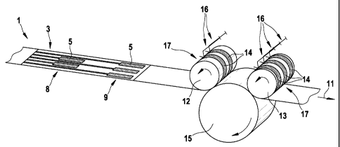
In Figure 3, two rollers of a sample fluid testing device according to the
present invention
are shown in rolling engagement with a test media tape.
CA 02650759 2008-10-28
WO 2007/125121 PCT/EP2007/054213
9
The test media tape 1 comprising a plurality of test media portions 3 (only
one shown in
Figure 3) is movable within the sample fluid testing device in the
longitudinal direction 11.
Each test media portion 3 comprises (in this case) five contact fields 5,
which are arranged
in two rows 8, 9 and which are to be electrically contacted. Two rollers 12,
13 are provided
for contacting the contact fields 5. The first roller 12 contains two annular
contact zones 14
and the second roller 13 contains three annular contact zones 14 on the
surface 17. Both
rollers 12, 13 are in rolling engagement with the test media tape 1. An
elastic roll 15 is
arranged on the side of the test media tape 1 opposite the side with the
rollers 12, 13 to
produce a contact pressure of the test media tape 1 against the rollers 12,
13. When the test
media tape 1 is moved in the longitudinal direction 11, the rollers 12, 13 and
the elastic roll
roll along the two surfaces of the test media tape 1 in different rotating
directions. When
the rollers 12, 13 reach a test media portion 3, the first roller 12
electrically contacts the
two contact fields 5 in the first row 8 with its two contact zones 14 and the
second roller 13
electrically contacts the three contact fields 5 in the second row 9 with its
three contact
15 zones 14. The contact zones 14 of both rollers 12, 13 are electrically
connected to a meter
(not shown) by sliding contacts 16.
CA 02650759 2008-10-28
WO 2007/125121 PCT/EP2007/054213
Reference Numbers
1 test media tape
2 tape
3 test media portion
4, 4' electrodes
5, 5' contact fields
6, 6' conductors
7 sensor field
8 first row
9 second row
10 transverse direction
11 longitudinal direction
12 first roller
13 second roller
14 contact zones
elastic roll
16 sliding contacts
17 surface