Note: Descriptions are shown in the official language in which they were submitted.
CA 02650794 2008-10-30
WO 2007/131340 PCT/CA2007/000828
METHOD AND APPARATUS FOR AUTOMATED DELIVERY OF THERAPEUTIC
EXERCISES OF THE UPPER EXTREMITY
FIELD OF THE INVENTION
The present invention relates to a method and apparatus for rehabilitation,
specifically in relation to physical therapy applied to the upper extremity.
BACKGROUND OF THE INVENTION
Impaired movement of the upper extremities often accompanies
neuromuscular disorders such as stroke, spinal cord injury, multiple
sclerosis,
peripheral nerve damage and arthritis. The motor deficits result in a loss of
independence, reduced quality of life and high costs of care. Stroke is the
leading
cause of upper extremity dysfunction. In developed countries, about 1.5% of
the
population live with the after-effects of stroke or about 5.5 million people
in North
America (American Heart Association, 2006). Functional recovery of the upper
extremity after stroke is quite poor, with 55% to 75% of patients having
significant
permanent deficits in performing activities of daily life (Lai etal., 2002).
The most widely used rehabilitative techniques are Neuro-Developmental
Treatment and Proprioceptive Neuromuscular Facilitation. Both are forms of
exercise therapy which have been shown to be effective if performed on a
regular
basis over weeks or months (Dickstein et al., 1986). Another technique,
Constraint
Induced Therapy, was recently developed specifically for the rehabilitation of
upper
extremity function and involves intensive exercise therapy of the affected arm
and
hand, typically six hours per day for two weeks (Taub et al., 1999).
Constraint
Induced Therapy has been widely adopted around the world since large gains in
function of the hemiplegic extremity in activities of daily life are achieved
after two
weeks.
However, the above techniques are time-consuming for therapists in that
1
CA 02650794 2008-10-30
WO 2007/131340 PCT/CA2007/000828
such techniques require one-on-one supervision, ideally on a daily basis.
Furthermore, the types of exercises involved tend to vary from one treatment
facility
to another. Reimbursement is usually limited to the time patients are in a
rehabilitation hospital. Following a hospital stay, patients are required not
only to
travel to physical therapy clinics, but also to absorb the costs of such
services
themselves. Such disadvantages prevent the large majority of potential
beneficiaries of exercise therapy from receiving it.
Those skilled in the art have attempted to provide methods and devices
suitable for machine delivery of exercise. For example, United States Patent
No.
6,007,459 to Burgess describes the use of an interactive video communications
link
which allows a therapist to supervise exercises performed by subjects located
elsewhere, for example in their homes.
Another approach is to provide a subject with an interactive robotic system
attached to the subject's limb. For example, United States Patent No.
5,466,213 to
Hogan et al. describes a robot which guides the limb along desired movement
paths
comprising a series of upper extremity exercises. The subject's robot can also
be
controlled remotely by a physical therapist using a second identical robot.
The
system can include a teleconferencing system allowing subject and therapist to
communicate with each other. However, this technology is highly expensive,
precluding it from widespread usage.
Other devices that impose movements on the hand have been suggested.
For example, United States Patent No. 5,746,704 to Schenck et al. teaches a
motorized exercise device for imposing movements along a specified path on a
digit
of the hand. Such passive motion devices are problematic, either in being
limited to
particular anatomical parts such as a single digit, or not enabling active
exercise of a
representative range of upper extremity movements required for activities of
daily
life.
United States Patent No. 5,755,645 to Miller etal. teaches a multiple degree
2
CA 02650794 2008-10-30
WO 2007/131340 PCT/CA2007/000828
of freedom passive exercise device in the form of a joystick with a telescopic
arm,
whereby the user grasps a handle and moves it in a three-dimensional
workspace.
Computerized control of two or more brakes creates programmable mechanical
resistances within the workspace. This device allows the performance of many
types of movement such as throwing a ball or swinging a baseball bat. Handle
attachments including tennis rackets, golf clubs and hockey sticks are
described.
However, the complexities of the mechanism, controllers and software place
this
device into a price category unaffordable for widespread distribution into
peoples'
homes. United States Patent No. 6,988,977 to Webber et al. describes a passive
exercise device with a multi-jointed arm. This device is intended as part of a
weight-
lifting machine for upper body training. Both Miller et al. and Webber et al.
describe
manipulanda in the form of handles which are easily grasped; yet, such
manipulanda are not even representative of the differently sized and shaped
objects
encountered in activities of daily life and which are most problematic for
people with
impaired hand function.
Exercise workstations have been designed with instrumented objects of
different sizes and shapes and sensors attached to the objects to provide
kinematic
data to a computer. Gritsenko etal. (2001) describes a workstation in the form
of a
desk surface, with fixed objects such as a spring-loaded doorknob, a spring-
loaded
caliper, a weighted handle and loose objects such as blocks and cylinders.
Gritsenko and Prochazka (2004) describes a workstation in the form of a
circular
table with a rotatable upper surface, bearing a similar range of fixed and
loose
objects. Taub et al. (2005) describes a cabinet with eight sets of fixed and
loose
objects arrayed on four work surfaces, each of which may be selected and
manually
pulled toward the subject from the cabinet. All of the described workstations
are
difficult to adjust, mechanically complex, bulky and expensive, rendering them
undesirable for widespread usage in peoples' homes.
United States Patent No. 6,613,000 to Reinkensmeyer etal. describes a
more affordable passive exercise device. A mass-produced computer input device
such as a joystick intended for computer games is used by the subject to
perform
3
CA 02650794 2008-10-30
WO 2007/131340 PCT/CA2007/000828
hand movements. Signals from the joystick sensors are used to provide input to
a
computer that communicates to a server computer through a computer network.
The server computer downloads individualized information to the subject's
computer,
specifying desired therapy and assessment exercises. The therapy and
assessment
exercises can be performed autonomously without real-time supervision from a
therapist. The drawback of the device is that the range of movements performed
by
the subject is limited to the motion of the top of the joystick, namely a
curved
surface. The joystick knob is relatively easy to grasp, unlike many objects
encountered in activities of daily life.
There is clearly a need for an inexpensive, straightforward device which
addresses significant daily tasks such as grasping, lifting, lowering, moving
side-to-
side, twisting and otherwise manipulating objects of different sizes and
shapes.
SUMMARY OF THE INVENTION
The present invention provides a method and apparatus for a range of
movement exercises representative of activities of daily life. Significantly,
the
invention can incorporate various exercise tasks considered important by
physical
therapists. The invention can provide quantified measures of performance
suitable
for computerized patient records. Advantageously, the invention is simple and
affordable, such that the health care system may be able to acquire and
distribute it
to the large numbers of people requiring sustained exercise therapy to improve
upper extremity function.
In a broad aspect, the invention provides a method for performing upper
extremity exercises by providing one or more manipulanda connected to a multi-
jointed, self-supporting arm, the one or more manipulanda capable of being
manipulated by a user to simulate movements representative of activities of
the
user's daily life.
In another broad aspect, the invention provides an apparatus to enable a user
4
CA 02650794 2008-10-30
WO 2007/131340 PCT/CA2007/000828
to perform upper extremity exercises, the apparatus comprising:
an arm having a fixed end and a free end, the fixed end being connected to a
base for securely supporting the arm and to locate the free end adjacent to
the user,
proximate to the user's upper extremities;
a plurality of joints formed in the arm at or between its fixed and free ends,
each joint having one or more rotational degrees of freedom while providing
resistance to rotational movement in the one or more degrees of freedom, such
that
the free end of the arm can be moved in three dimensional space, and such that
the
arm is self-supporting; and
a manipulandum assembly comprising a plurality of manipulanda attached to
the free end of the arm in a manner such that each manipulandum can be moved
by
the user through the one or more rotational degrees of freedom provided by the
plurality of joints, each manipulandum being positioned within hand grasping
range
of the user, and each manipulandum being or representing an object encountered
in
an upper extremity activity of the user's daily life.
In a preferred embodiment, the plurality of manipulanda are fixed or tethered
to the free end of the arm such that the manipulanda so connected remain
accessible to the user without dropping or becoming lost.
In another preferred embodiment, one or more of the manipulanda are
attached to the free end of the arm such that an additional rotational degree
of
freedom is provided to the manipulanda so attached.
In another preferred embodiment, one or more of the manipulanda are
mounted on a rotatable shaft connected at the free end of the arm such that
the
additional rotational degree of freedom is provided along the long axis of the
shaft.
In another preferred embodiment, the plurality of joints provides passive
resistance against rotational movement, and thereby returns the arm and the
manipulandum assembly to an equilibrium rest position when the user releases
the
manipulandum assembly.
CA 02650794 2008-10-30
WO 2007/131340 PCT/CA2007/000828
In yet another preferred embodiment the arm is positioned above a floor, and
wherein the arm is formed in two interconnected segments with a first segment
extending generally upwardly from the base and a second segment extending
generally forwardly toward the user to position the free end proximate the
user's
upper extremities, the first segment having the fixed end connected to the
base
through a first joint providing a rotational degree of freedom in a horizontal
axis
generally parallel to the floor, and a rotational degree of freedom in a
vertical axis,
the first and second segments being interconnected through a second joint
providing
a rotational degree of freedom in a horizontal axis, and the free end of the
second
segment being attached to the plurality of manipulanda through a third joint
providing a rotational degree of freedom in a horizontal axis.
Preferred and exemplary manipulanda of the present invention are selected
from a vertically split cylinder, a doorknob manipulandum, a key-grip
manipulandum,
horizontal handles manipulandum, a peg manipulandum and a coin manipulandum.
In a further preferred embodiment the apparatus includes one or more
sensors located in one or more positions selected from the first, second and
third
joints, the first and second segments, and the plurality of manipulanda, the
sensors
being operative to detect movement or force and to generate an electrical
signal
representative of movement or force generated.
In another broad aspect, the invention extends to a method for providing an
exercising therapy for the user's upper extremity comprising providing an
apparatus
as described above, and causing the user to manipulate the plurality of
manipulanda
with the user's hand to simulate movements representative of activities of the
user's
daily life. Preferred forms of manipulating include grasping, squeezing,
releasing,
pinching, lifting, lowering, moving from side to side, twisting and rotating.
BRIEF DESCRIPTION OF THE DRAWINGS
The present invention will be further described by way of example only and
6
CA 02650794 2008-10-30
WO 2007/131340 PCT/CA2007/000828
with reference to the following figures in which similar references are used
in
different figures to denote similar components, and wherein:
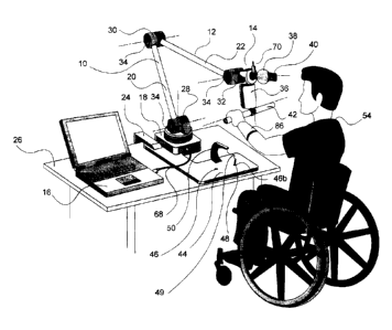
Figure 1 is a perspective view of one embodiment of the present invention,
showing the multi-jointed arm providing multiple rotational degrees of freedom
to the
plurality of manipulanda attached to the free end of the arm.
Figure 2 is a perspective view of the split cylinder manipulandum of one
embodiment of the present invention, showing the user grasping and squeezing
manipulations on the split cylinder.
Figures 3A and 3B are perspective views of the doorknob manipulandum of
one embodiment of the invention. Figure 3A is a perspective view of the
doorknob
manipulandum positioned towards the user. Figure 3B is a perspective view of
the
doorknob manipulandum in a rotated, upright position.
Figure 4 is a perspective view of the key-grip manipulandum of one
embodiment of the invention.
Figure 5 is a perspective view of the horizontal handles manipulandum of one
embodiment of the invention.
Figure 6 is a perspective view of the pegboard and tethered peg
manipulandum of one embodiment of the invention.
Figure 7A is a perspective view of the peg manipulandum and the coin
manipulandum of one embodiment of the invention.
Figure 7B is a perspective view of the peg and coin manipulandum of Figure
7A, showing the peg and coin housing parts in cross section to show the spring
loaded peg, tethered coin and sensor details.
7
CA 02650794 2008-10-30
WO 2007/131340 PCT/CA2007/000828
Figure 7C is a perspective view of the coin manipulandum of Figure 7A,
showing the user manipulating the coin manipulandum in a manner to simulate
picking up the coin element.
Figure 8 is a flowchart illustrating one embodiment of computer software
which might be used for interactive user prompting, scoring and transmitting
to a
remote location.
BRIEF DESCRIPTION OF THE PREFERRED EMBODIMENTS
The invention broadly provides a method and apparatus for physical therapy
for various disorders in which movement of the upper extremity is impaired.
The
apparatus has a multi-jointed, self-supporting arm, the joints of which
provide
resistance (preferably passive resistance) to rotational movement in one or
more
degrees of freedom. One end of the arm, a connected end, is connected to a
support for securely supporting the arm and for positioning the arm at an
appropriate
user height. The other end of the arm, the free end bears one or more
manipulanda
simulating movements representative of activities of the user's daily life.
The design
of the arm allows movement to any point within the biomechanical workspace of
the
user's hand. Each manipulandum in the assembly is designed to provide a
specific
hand and/or arm exercise involving certain movements representative of those
occurring in an activity of daily life. The specific exercise provided by each
manipulandum is similar to those used in conventional physical therapy for
subjects
with impaired movement of the upper extremities resulting from neuromuscular
disorders. Such disorders can include, for example, stroke, spinal cord
injury,
multiple sclerosis, peripheral nerve damage and arthritis.
The following description is a preferred embodiment of the invention by way
of example only and without limitation to the combination of features
necessary for
carrying out the invention into effect.
The invention is described with reference to the drawings in which like parts
8
CA 02650794 2008-10-30
WO 2007/131340 PCT/CA2007/000828
are labeled with the same numbers in Figures 1 to 8. The apparatus is shown
generally at 10 in Figure 1 to include a multi-jointed arm 12 with a connected
manipulandum assembly 14 and computer 16.
The arm 12 is composed of a base assembly 18, a first segment 20 and a
second segment 22. The base assembly 18 is securely anchored by appropriate
securing means, for example a clamp 24, to a horizontal support 26, for
example, a
desk, table or other suitable support. The base assembly 18 is connected to
the
fixed end of the first segment 20 by a first spring-loaded joint 28,
preferably having
two rotational degrees of freedom (as indicated by dashed lines in Figure 1 -
showing rotational movement about a horizontal and a vertical axis). The first
segment 20 is linked to the second segment 22 by a second spring-loaded joint
30,
preferably having a single rotational degree of freedom (as indicated by the
dashed
line in Figure 1 - showing rotation about a horizontal axis). The manipulandum
assembly 14 is connected to the free end of the second segment 22 by a third
spring-loaded joint 32, preferably having a single rotational degree of
freedom (as
indicated by the dashed line in Figure 1- showing rotation about a horizontal
axis).
In Figure 1, the free end of the arm 12 (or segment 22) terminates at the
third joint
32.
The first and second segments 20, 22 can be formed of a rigid material.
Alternatively, telescopic, elastic, or rotational segments can be used to
provide
additional degrees of freedom beyond those of the rigid segments 20, 22
illustrated
in Figure 1. Such segments may be instrumented to measure deflection,
extension,
compression and rotation.
Each of the spring-loaded joints 28, 30, 32 can be locked in a certain
position
using any known locking means (not shown) within its respective range of
motion if
so desired. One example of suitable locking means is a bolt and wing nut. Each
spring-loaded joint 28, 30, 32 provides passive resistance to angular
deflection away
from a static equilibrium position (equilibrium rest position) determined by
the mass
and spring properties of the components of the apparatus 10. In this manner,
the
9
CA 02650794 2008-10-30
WO 2007/131340 PCT/CA2007/000828
multi-jointed arm 12 is self-supporting, and will return to its equilibrium
rest position
when the user completes a particular manipulation, releasing a manipulandum.
Springs are incorporated in the joints 28, 30, 32 to achieve a desired amount
of
passive resistance in movement. Alternatively, a desired amount of resistance
is
achieved using friction bearings, dampers or weights, although springs are
preferable. It is understood that these means of resistance may be varied,
thus
allowing for alterations in manipulanda, user and user capabilites. Each
spring-
loaded joint 28, 30, 32 in the arm 12 is preferably equipped with a sensor 34
for
electrically measuring its angle of deflection around its respective
rotational axis or
axes.
The exemplary embodiment incorporates spring-loaded joints 28, 30, 32. It is
possible to modify the invention to incorporate other suitable types of
joints, for
example, joints having additional rotational degrees of freedom, differing or
absent
spring-loading, differing or absent locking means, and different
instrumentation. For
instance, a ball and socket joint can be used to connect the first and second
segments 20, 22. The ball and socket joint may be spring-loaded, or may rely
on
friction to maintain a position. Advantageously, the ball and socket joint has
rotational degrees of freedom around two axes, and can be instrumented with
sensors 34 that measure deflection of the joint around its two degrees of
freedom.
In general, any joints or linkages which provide one or more rotational
degrees of freedom with some resistance to rotational movement are suitable.
Most
preferably, the joints provide only passive resistive force against rotational
movement, such as by frictional, spring, gravitational, or inertial force. It
should be
understood that the provision of passive resistance to rotational movement in
the
joints is meant to exclude the use of force generators or robotic devices.
One or more moving components of the apparatus 10 (for example, arm,
segments, joints, manipulanda, and pegboard holes) are instrumented with
electronic sensors 34 (see also sensors 74, 84 described below with particular
manipulanda). The sensors 34 detect the movement of one or more moving
CA 02650794 2008-10-30
WO 2007/131340 PCT/CA2007/000828
components and generate electrical signals representative of the movement. The
electrical signals are then transmitted to a suitable processing device, such
as the
computer 16, which then samples, displays, stores and processes the signals
into
kinematic or kinetic variables. Secondary variables such as, for example, net
displacement, velocity, acceleration, force and torque, are computed from the
kinematic or kinetic variables to generate performance ratings or scores. It
has been
found advantageous to compute a single performance rating by first normalizing
each individual rating corresponding to a given exercise and combining all
such
ratings into a single score (see for example, Gritsenko & Prochazka, 2004).
Various types of sensors 34 are appropriate with the apparatus 10. The
exemplary embodiment uses potentiometers to determine the angle of a joint or
the
position of the first and second segments 20, 22. Other non-limiting examples
include potentiometers, gyroscopes, accelerometers, linear variable
displacement
transducers, optical encoders, strain gauges, electrical contacts, photo-
electric
sensors or other sensors known to those skilled in the art. Optical, electro-
optical,
magnetic, capacitive, inductive or other types of sensors can be used to
quantify
movement, position, orientation, or force applied to all or any combination of
joints,
segments, and manipulanda. In this manner, movement sensors located on one or
more of the arm 12, segments 20, 22, joints 28, 30, 32 and manipulandum
assembly
14 can be used to detect and transmit information from which one may calculate
angles, starting and end point positions of components so as to generate
information
relating to the x, y and z co-ordinates of one or more of the manipulanda
being
moved by the user 54.
The manipulandum assembly 14 is connected to the free end of the second
segment 22 through the joint 32. The manipulandum assembly preferably includes
a platform 81 which extends forwardly from (i.e., toward the user), and is
connected
to, the joint 32. In this manner, the manipulandum assembly 14 can suspend a
plurality of hand function manipulanda in front of the user, allowing the user
to grasp
each manipulandum with one or both hands, and move the manipulandum through
the multiple degrees of freedom allowed by the joints 28, 30, 32. The platform
81
11
CA 02650794 2008-10-30
WO 2007/131340 PCT/CA2007/000828
can be positioned generally horizontally, as shown in Figure 3A, or it can be
moved
to be generally vertical as shown in Figure 3B, by rotating the joint 32 along
its
horizontal axis. The manipulandum assembly 14 preferably also includes a shaft
66
mounted perpendicularly to the platform 81 (preferably below, as shown in
Figure
3A). The shaft 66 is preferably connected to the platform 81 for rotation
about its
long axis (shown in Figure 3A as a vertical dotted line representing a
vertical axis
when the manipulandum apparatus 14 is in its upright position). This allows
for
connection of manipulanda as described below to this rotatable shaft 66,
adding an
additional rotational degree of freedom to a manipulandum of the manipulandum
assembly 14. As shown in Figure 1, the user 54 can move the manipulandum
assembly 14, relative to the user, forwardly or rearwardly, up and down, and
in a
twisting or side to side movement, with the twisting or side to side movement
being
achieved through the vertical axis through joint 28 and/or the long axis of
the
rotatable shaft 66. Locking of one or more of these joints 28, 30, 32 or the
rotatable
shaft 66 to limit any of these rotational degrees of freedom may be achieved
with the
locking means (not shown), as mentioned below. Thus, the multi-jointed arm 12
allows for 3-dimensional movement of the manipulandum assembly 14, which can
be sensed to generate x, y, and z components of the movements of the
individual
manipulandum by the user.
Another preferred feature of the manipulandum assembly 14 is that it allows
for the one or more manipulanda to be fixed or tethered at the free end of the
arm
12. In this manner, the manipulanda remain accessible to the user, without
individual components being dropped or lost by the user.
The manipulandum assembly 14 is comprised of an electrically instrumented
set of manipulanda which are self-supporting and provide resistance. Movement
of
such manipulanda requires upper extremity movements similar to those occurring
in
activities of daily life. Varied manipulanda are attached or detached from the
arm
12, depending on the user's disorder, requirements or maintenance needs. It
will be
appreciated by those skilled in the art that different manipulanda can be
connected
to the arm 12 at different locations and with differing and/or additional
degrees of
12
CA 02650794 2008-10-30
WO 2007/131340 PCT/CA2007/000828
freedom (i.e., additional to the rotational degrees of freedom provided by the
joints
28, 30 and 32). As described in more detail below, additional sensors (i.e.,
in
addition to sensors 34 located on the arm12, segments 20, 22 and/or joints 28,
30
and 32) are preferably included to measure displacements of different
manipulanda
within the manipulandum assembly 14, from which secondary variables (for
example, kinematic variables) are computed.
Without being limiting in any manner, the manipulandum assembly 14 may
include, for example, one or more of a vertically split cylinder manipulandum
36; a
doorknob manipulandum 38; a key-grip manipulandum 40; a horizontal handles
manipulandum 42; a peg manipulandum 70; a coin manipulandum 80, or other
suitable hand function manipulanda as used in conventional physical therapy
for
users with impaired movement of the upper extremity. As described more fully
below, these manipulanda are preferably attached to the platform 81, to rotate
with
the joint 32, and/or to the rotatable shaft 66.
As shown in Figures 1 and 6, stationary manipulanda may be provided on a
horizontal support 26 in front of the user. Figure 6 shows one such exemplary
additional manipulandum in the form of a pegboard 44 defining one or more
holes
46 and having at least one peg 48 tethered by a tether 49 from a gantry 50 can
be
used alone or in combination with the apparatus 10.
Figure 2 shows the vertically split cylinder 36 defining two halves 52a, 52b
mounted on the rotatable shaft 66, and which are biased slightly away from
each
other by one or more stiff springs (not shown). The split cylinder 36 doubles
as a
caliper for squeezing or a familiar object such as a pop can. Force may be
sensed
indirectly by displacement of the spring separating the two halves 52a, 52b of
the
split cylinder 36, or by a force transducer such as a strain gauge attached to
part of
the cylinder (sensor not shown). Figure 2 illustrates the user 54 applying
force to
squeeze the two halves 52a, 52b of the split cylinder 36 together. The user 54
can
also practice moving the split cylinder 36 from one position to another
position within
the workspace, mimicking the transfer of a familiar object such as a pop can
from
13
CA 02650794 2008-10-30
WO 2007/131340 PCT/CA2007/000828
one location to another location.
Figures 3A and 3B show the doorknob manipulandum 38 comprising a
rotatable spring-loaded doorknob 56 fixed for rotation to the platform 81. The
doorknob 56 provides twisting (pronation-supination) exercises for the user
54, as
shown in Figure 3A. Conveniently, the doorknob 56 is rotatable into a vertical
position, whereby the exercise requires a movement similar to that of twisting
the lid
of a screw-top jar, as shown in Figure 3B. In other embodiments of the
invention,
the doorknob 56 can be replaced by different manipulanda. Non-limiting
examples
include a sphere, oval, lever or other shapes which simulate other activities
of daily
life.
Figure 4 shows a key-grip manipulandum 40 comprising a key-like tab 58
extending outwardly from a key way 60 defined in the doorknob 56. The key-like
tab
58 is configured to be pulled outwardly from the key way 60 by the user 54 to
a pre-
configured locked position, so that the key-like tab 58 cannot be completely
removed
from or drop out of the key way 60. The key-like tab 58 can be twisted in a
movement which mimics the turning of a key in a lock.
Figure 5 shows the horizontal handles manipulandum 42 comprising
horizontal handles 62 freely rotatable on an axle 64 which is secured to the
base of
the rotatable shaft 66, below the split cylinder 36. The handles 62 are
positioned
perpendicular to the split cylinder 36 (when in the equilibrium rest position)
and
extend horizontally beyond the periphery of the split cylinder 36 so as to be
accessible to both the left and right hands of the user 54. The handles 62
rotate
freely on the axle 64 which is connected to the manipulandum assembly 14,
which,
when combined with the degrees of freedom of the arm 12, allow any orientation
of
the user's hand 54 in the three-dimensional workspace. Advantageously, the
handles 62 provide range-of-motion exercises encompassing virtually the entire
biomechanical range of possible positions of the user's hand 54.
The exemplary embodiment can also be provided with a pegboard 44
14
CA 02650794 2008-10-30
WO 2007/131340 PCT/CA2007/000828
attached to the horizontal support 26 as shown in Figure 6. The pegboard 44
defines one or more holes 46, and has at least one peg 48 tethered by a tether
49
from a gantry 50. The pegboard 44 can be used alone or in combination with the
apparatus 10. In use, the user 54 moves the peg 48 from a first hole 46a to a
second or other hole 46b in order to practice side-to-side movement of the
hand 54
(the movement of the hand 54 is shown in phantom in Figure 6). Sensors 34 can
be
positioned within the one or more holes 46 to monitor or assess the user's
progress.
Figures 7A, 7B and 7C show exemplary embodiments of a peg
manipulandum 70 and a coin manipulandum 80 also provided at the free end of
the
arm 12, preferably forward of the platform 81. A peg 71 with an enlarged base
is
held captive in a hollow housing 72. A spring 73 within the housing normally
pushes
the enlarged base of the peg 71 against a sensor 74 such as a microswitch
located
at the bottom of the housing 72. In use, the user 54 grasps the peg 71 in a
pinch
grip and pulls it part of the way out of the housing 72 against the resistance
of the
spring 73. This changes the state of the sensor 74. In addition to peg 71
being
pulled partly out of the housing 72, it may also be moved in any direction in
3-
dimensional space by virtue of its attachment to the moveable manipulandum
assembly 14. The movement of the peg 71 and attached manipulandum assembly
14 may be computed from signals from the sensors 34.
The coin manipulandum 80 is shown to be mounted on the platform 81,
although it might be mounted at an alternate convenient location on the
manipulandum assembly 14 (it might still alternatively be mounted on the
horizontal
support 26, if desired). A coin element 82 is held flat on the platform 81.
The coin
element 82 may be tethered beneath the platform 81 in any suitable manner such
that its removal from the platform 81 as the user picks up the coin element 82
may
be sensed. Figure 7B shows one exemplary embodiment in which the cross
sectional details show a tether 85 connected to the underside of the coin
element
82. The tether 85 is secured below the platform 81 to a self retracting spring
biased
reel 83. A motion sensor 84 may be mounted to the reel 83 in order to sense
rotation of the reel 83 as the user 54 picks up the coin element 82.
CA 02650794 2008-10-30
WO 2007/131340 PCT/CA2007/000828
While not specifically shown in the Figures, it will be understood by one
skilled in the art that the apparatus and method of this invention may include
one or
more supporting devices for the user's hands or arms. Such supports might
include,
for example, elbow supports or overhead slings. As well, the invention might
be
adapted to use hand straps with one or more of the manipulanda in order to
assist a
user.
When the apparatus 10 is in use, the user 54 is generally seated and facing
the manipulandum assembly 14, as shown in Figure 1. The user 54 engages one of
the manipulanda by grasping and lifting, lowering, pulling, pushing, twisting
or
otherwise moving it according to the activities of daily life being simulated,
and
according to a series of instructions provided by software in the computer 16,
for
example on the display or by a remote therapist communicating via a
telecommunications link such as that mediated by the computer 16 through a
network. The movements of the first, second and third spring-loaded joints 28,
30,
32 and first and second segments 20, 22 of the apparatus 10 are detected by
the
sensors 34. The sensors 34 in turn generate electrical signals representative
of the
movement, and transmit the electrical signals by suitable transmission means
68 (for
example, a wire or wireless means) to a processing device such as the computer
16,
which then samples, displays, stores and processes the signals into kinematic
or
kinetic variables. The kinematic or kinetic variables can be further processed
to
obtain secondary variables.
The computer 16 runs a software program that provides feedback and
instruction to the user 54 based on the user's movements. The computer 16 also
stores data captured by the sensors 34. The data may be processed subsequently
to quantify changes in the user's ability to perform simulated activities of
daily life
over a period of time. A report of the user's progress may be periodically
sent over a
computer network to a computer located remotely for a therapist or trainer for
analysis, for example through the Internet. The therapist or trainer can issue
commands to the computer 16, locally or over a computer network, to modify or
change the feedback and instruction the user 54 receives from the computer 16.
16
CA 02650794 2008-10-30
WO 2007/131340 PCT/CA2007/000828
The computer interface can comprise different assemblies including, for
example, both wired and wireless interfaces, for example USB and 802.11b,
respectively. Computer programs of different types and levels of network and
device
connectivity can be used. Without being limiting in any manner, such types can
include stand-alone applications, applications run from remote locations over
a
computer network, game applications, exercise applications and training
applications. The computer program may offer many kinds of feedback to the
user
including audio and/or video. For instance, the computer program can allow an
administrator either locally or by means of a computer network to communicate
with
the user in real time, or with a delay, by way of text, audio visual, or other
type of
communication.
One example of computer software that can be used to guide the user 54
through a series of motor tasks that collectively comprise a standardized test
of
upper extremity function is shown in the flowchart of Figure 8. Communication
with
the user 54 may be in the form of automatically generated voice commands,
displayed text, pictures, videos and animations on the user's computer display
16.
Alternatively or additionally, an administrator or therapist may provide
verbal and
visual guidance. As described above, the administrator may be in the same
location
or elsewhere, communicating verbally and visually by telecommunications means,
for example with the use of the Internet. The software may record signals
captured
by the sensors 34 etc. during the performance of the standardized test and use
these signals automatically to detect whether a specific task has or has not
been
attempted and prompt the user accordingly. The software may automatically
compute performance scores from the captured data and thereby provide outcome
measures from the standardized test.
The computer 16 can be a standalone workstation, or connected to a
computer network. When connected to a network, the computer program can use a
wide range of connectivity protocols over a link with the network. The
computer 16
can be connected to multiple forms of networks simultaneously, for example a
computer network and a cellular network.
17
CA 02650794 2013-04-30
The exemplary embodiment can be provided with an electrical stimulator 86
to activate the nerves and muscles of the user 54 to assist in the performance
of the
exercise (see for example, International Patent Application Publication No. WO
2004/034937 and United States Patent No. 6,961,623 issued November 1, 2005,
both to Prochazka).
All references mentioned in this specification are indicative of the level of
skill
in the art of this invention. Some references provided herein provide details
concerning the state of the art prior to the filing of this application, other
references
may be cited to provide additional or alternative device elements, additional
or
alternative materials, additional or alternative methods of analysis or
application of
the invention.
The terms and expressions used are, unless otherwise defined herein, used
as terms of description and not limitation. There is no intention, in using
such terms
and expressions, of excluding equivalents of the features illustrated and
described, it
being recognized that the scope of the invention is defined and limited only
by the
claims which follow. Although the description herein contains many specifics,
these
should not be construed as limiting the scope of the invention, but as merely
providing illustrations of some of the embodiments of the invention. One of
ordinary
skill in the art will appreciate that elements and materials other than those
specifically exemplified can be employed in the practice of the invention
without
resort to undue experimentation. All art-known functional equivalents, of any
such
elements and materials are intended to be included in this invention. The
invention
illustratively described herein suitably may be practiced in the absence of
any
element or elements, limitation or limitations which is not specifically
disclosed
herein.
As used herein, "comprising" is synonymous with "including," "containing," or
"characterized by," and is inclusive or open-ended and does not exclude
additional,
unrecited elements. The use of the indefinite article "a" in the claims before
an
element means that one or more of the elements is specified, but does not
18
CA 02650794 2013-04-30
specifically exclude others of the elements being present, unless the contrary
clearly
requires that there be one and only one of the elements.
REFERENCES
American Heart Association: Heart Disease and Stroke Statistics - 2006 Update,
Dallas, Texas. p. 40).
Dickstein, R.; Hocherman, S.; Pillar, T. and Shaham, R. (1986) Stroke
rehabilitation.
Three exercise therapy approaches. Physical Therapy 66:1233-8.
Gritsenko, et al. (2001) Automated FES-assisted exercise therapy for
hemiplegic
hand function. Society for Neuroscience Abstracts 27:210.220
Gritsenko, V. and Prochazka, A. (2004) A functional electric stimulation-
assisted
exercise therapy system for hemiplegic hand function. Archives of Physical
Medicine and Rehabilitation 85:881-885.
Taub, E.; Lum, P.S.; Hardin, P.; Mark, V.W. and Uswatte, G. (2005) AutoCITE:
automated delivery of CI therapy with reduced effort by therapists. Stroke
36:1301-1304.
Lai, S.M.; Studenski, S.; Duncan, P.W. and Perera, S. (2002) Persisting
consequences of stroke measured by the Stroke Impact Scale. Stroke
33:1840-4.
Taub, E.; Uswatte, G. and Pidikiti, R. (1999) Constraint-Induced Movement
Therapy:
a new family of techniques with broad application to physical rehabilitation--
a
clinical review. Journal of Rehabilitation Research & Development 36:237-
251.
PATENT DOCUMENTS
Burgess, B. Method and system for providing physical therapy services. United
States Patent No. 6,007,459, issued December 28, 1999.
Hogan, N.; Krebs, H.I.; Sharon, A.; and Charnnarong, J. Interactive robotic
therapist. United States Patent No. 5,466,213, issued November 14, 1995.
Miller, L.C.; Ulrich, N.; Townsend, W.T.; Yoerger, D.; Matsuoka, Y.; and
Larocque,
19
CA 02650794 2013-04-30
B.D. Exercise apparatus. United States Patent No. 5,755,645, issued May 26,
1998.
Prochazka, A. Method and apparatus for controlling a device or process with
vibrations generated by tooth clicks. International Patent Application
Publication No. WO 2004/034937, published October 16, 2003.
Prochazka, A. Method and apparatus for controlling a device or process with
vibrations generated by tooth clicks. United States Patent No. 6,961,623,
issued November 1, 2005.
Reinkensmeyer, D.J.; Painter, C.C. and Pang, C.T. Method and apparatus for
mass-
delivered movement rehabilitation. United States Patent No. 6,613,000,
issued September 2, 2003.
Schenck, R.R. and Krevald, W.R. Therapy apparatus having a passive motion
device for flexing a body member. United States Patent No. 5,746,704,
issued May 5, 1998.
Webber, R.T. and Zink, G.M. Exercise arm assembly for exercise machine. United
States Patent No. 6,988,977, issued January 24, 2006.