Note: Descriptions are shown in the official language in which they were submitted.
CA 02651035 2008-10-30
WO 2007/143273 PCT/US2007/066384
EVACUATION DEVICE
FIELD OF INVENTION
[0001] The invention pertains generally to air moving devices and methods and
more
particularly to evacuation devices and methods for removing air from
containers. The
invention finds particular applicability in the field of food preservation.
BACKGROUND
[0002] It is known that storing food items in an environment evacuated of air
will
help preserve and prolong the freshness of those items. To accomplish this,
the food
items may be placed in an internal volume of a rigid container which is then
sealed and
air trapped in the internal volume is removed. To enable evacuation of the
internal
volume, the container may include a one-way valve element communicating with
the
internal volume. The one-way valve element allows for the evacuation of
trapped air
while preventing the ingress of the surrounding environmental air into the
interior volume
thereby preserving the evacuated state.
[0003] A variety of different evacuation devices have been employed for
actually
evacuating air through the one-way valve element. Examples of such evacuation
devices
include hand operated pumps in which continuous hand manipulation is required
to
provide the pumping action. Other evacuation devices may be electrically
activated and
may be configured as either counter-top designs or as hand-held designs.
Desirably, such
electrical evacuation devices should operate smoothly and quietly and, when
configured
as hand-held devices, should be sufficiently lightweight and compact.
SUMMARY OF THE INVENTION
[0004] The invention provides an evacuation device for evacuating air from the
internal volume of a container via a one-way valve element. The evacuation
device
includes an electrical motor having a rotating shaft extending from the front
face of the
motor. The rotating shaft defines an axis line that extends through the
evacuation device.
1
CA 02651035 2008-10-30
WO 2007/143273 PCT/US2007/066384
The evacuation device also includes a reciprocal member movable in a chamber
in a
linear direction parallel to or along the axis line. The reciprocal motion of
the reciprocal
member in the linear direction parallel to or along the axis line provides a
pumping action
for removing air from a container.
[0005] To operatively connect the motor to the reciprocal member such that
rotation
of the motor shaft can be converted into linear motion of the reciprocal
member parallel
to the axis line, the evacuation device includes a cam and a yoke. The cam is
mounted to
the shaft and includes a cylindrical sidewall into which is disposed a slot or
channel. The
channel extends about the circumference of the cylindrical sidewall in a
sinusoidal
pattern such that the channel alternately moves towards and away from the
chamber. The
sinusoidal pattern also extends concentrically about the axis line. The yoke
at one end is
connected to the reciprocal element and at the other end includes at least one
follower
element that is received into the channel of the cam.
[0006] Rotation of the motor shaft therefore rotates the cam with respect to
the
follower element such that the follower element is forced to move through the
rotating
sinusoidal pattern provided by the channel. Because the sinusoidal pattern is
concentric
about the axis line, the forced movement of the follower element is converted
to linear
reciprocal displacement of the yoke and the connected reciprocal element along
the axial
direction.
[0007] In another aspect of the invention, the evacuation device can be
configured
with features that provide for adjusting or controlling the vacuum pressure of
the device.
The adjustment or control features can operate by allowing ambient air to
enter the
system during evacuation.
[0008] An advantage of the invention is that it provides an evacuation device
for
evacuating air from a container in order to preserve food items. Another
advantage is
that the evacuation device converts rotational motion of a motor shaft to
linear motion of
a reciprocal element so as to provide a pumping action. This advantage allows
for
compact sizing and stable operation of the evacuation device. These and other
2
CA 02651035 2008-10-30
WO 2007/143273 PCT/US2007/066384
advantages and features of the invention will become apparent from the
detailed
description and the accompanying drawings.
BRIEF DESCRIPTION OF THE DRAWINGS
[0009] Figure 1 is a perspective view of an evacuation device for evacuating a
container designed in accordance with the teachings of the invention.
[0010] Figure 2 is a perspective cross-sectional view taken along line 2-2 of
Figure 1
showing the internal components of the evacuation device with the housing
removed.
[0011] Figure 3 is an exploded view of the evacuation device illustrating the
arrangement of the components.
[0012] Figure 4 is a perspective view of a cylindrical cam including a
sinusoidal
channel adapted to engage the illustrated follower elements for use with the
evacuation
device.
[0013] Figure 5 is an elevational cross-sectional view similar to that taken
along line
2-2 showing the evacuation device engaging a container and conducting an
intake stroke
during operation.
[0014] Figure 6 is a elevational cross-sectional view similar to that taken
along line
2-2 showing the evacuation device engaging a container and conducting an
exhaust
stroke during operation.
[0015] Figure 7 is a perspective view of the evacuation device and a storage
bag.
[0016] Figure 8 is a perspective view of another embodiment of an evacuation
device
with a pressure adjustment feature.
[0017] Figure 9 is a plan view of the evacuation device shown in Figure 8.
[0018] Figure 10 is a plan view of the evacuation device shown in Figure 9
with the
pressure adjustment feature shown in a different position.
[0019] Figure 11 is a front perspective view of an embodiment of a one-way
valve
element for use with flexible bags of the invention.
[0020] Figure 12 is a rear perspective view of the one-way valve element of
Figure
11.
3
CA 02651035 2008-10-30
WO 2007/143273 PCT/US2007/066384
[0021] Figure 13 is a cross-sectional view through the one-way valve element,
as
taken along line 13-13 of Figure 11.
[0022] Figure 14 is an exploded view of another embodiment of the one-way
valve
element for attachment to the flexible bag.
[0023] Figure 15 is an exploded view of another embodiment of the one-way
element
for attachment to the flexible bag.
[0024] Figure 16 is a perspective cross-sectional view similar to that taken
along line
2-2 of Figure 1 showing the internal components of another embodiment of the
evacuation device configured with a vacuum control valve.
[0025] Figure 17 is a perspective exploded view of the embodiment of the
evacuation
device of Figure 16.
[0026] Figure 18 is an elevational cross-sectional view showing the evacuation
device of Figure 16 engaging a container and conducting an intake stroke
during
operation with the vacuum control valve closed
[0027] Figure 19 is an elevational cross-sectional view showing the evacuation
device of Figure 16 engaging a container and conducting an exhaust stroke
during
operation with the vacuum control valve closed.
[0028] Figure 20 is an elevational cross-sectional view similar to FIG. 18
with the
valve control element opened.
[0029] Figure 21 is a schematic view of another embodiment of the cam and yoke
configured to include first and second channels after completion of an intake
stroke.
[0030] Figure 22 is a schematic view of the cam and yoke of Figure 21 after
completion of an exhaust stroke.
[0031] Figure 23 is a view of another embodiment of a hand held vacuum device
having a user selectable pressure control feature including a slide and
alignable holes.
[0032] Figure 24 is a front elevational view of the hand held evacuation
device of
Figure 23 showing the pressure control feature in a different position.
4
CA 02651035 2008-10-30
WO 2007/143273 PCT/US2007/066384
DETAILED DESCRIPTION OF THE EMBODIMENTS
[0033] Now referring to the drawings, there is illustrated in FIG. 1 an
electrically
operated evacuation device 100 designed in accordance with the invention. The
immediate embodiment of the evacuation device 100 is configured to be hand-
held
though, in other embodiments of the invention, could be configured as a
countertop
design. The illustrated evacuation device 100 includes an elongated housing
102 that
extends between a rearward circular closed end 104 and a forward skirt-like
nozzle end
106 that outlines an intake volume 108. In use, the nozzle end 106 is intended
to be
placed against or about a one-way valve element attached to a container so the
valve
element is exposed to the intake volume 108. Preferably, the area of the skirt-
like nozzle
end 106 is sufficiently large to fit about a variety of different valve
elements. In the
illustrated embodiment, the nozzle end has a generally square shape in
contrast to the
circular shape of the rearward closed end. The evacuation device 100 tapers
slightly
outward between the closed end 104 and the nozzle end 106 so that the main
body
portion 112 can function as a handle. For purposes of reference, an axis line
110 extends
through and aligns the closed end 104, body portion 112, and nozzle end 106.
The
housing 102 can be made from any suitable material including injection
moldable
thermoplastic material.
[0034] To selectively activate the evacuation device 100, a switch 114 can be
disposed along the body portion 112 of the housing 102. Furthermore, to
establish
electrical communication with an electrical socket, the evacuation device 100
also
includes a power cord 116 extending from the closed end 104. However, in other
embodiments, instead of communicating with power sockets, the electrical
evacuation
device 100 can be configured to operate from batteries that are to be placed
inside the
housing 102.
[0035] Referring to FIGS. 2 and 3, the components of the evacuation device 100
that
are typically enclosed in the housing include an electrically activated motor
120. The
motor can be configured to operate on either AC or DC electricity depending
upon the
power source that the evacuation device 100 is intended to employ. Extending
from a
CA 02651035 2008-10-30
WO 2007/143273 PCT/US2007/066384
front face 122 and generally concentric with the rest of the motor 120 is a
rotatable motor
shaft 124. As will be appreciated, activating the motor causes rotation of the
shaft 124.
Furthermore, the shaft 124 extends along and thereby determines the position
of the axis
line 110. As illustrated in FIG. 2, the motor 120 can be selectively activated
to rotate the
shaft 124 by depressing switch 114.
[0036] Abutting against the front face 122 of the motor 120 is a motor grill
130 that
helps support and locate the motor within the housing. Disposed generally
through the
center of the motor grill 130 is an aperture 132 through which the motor shaft
124 can
pass. Located axially forward of and adjacent to the motor grill 130 is a bore
housing
134 that has a generally tubular body 136 extending from a flange 138
positioned to abut
the motor grill 130. The tubular body 136 provides a bore 140 that, when the
bore
housing 134 is assembled with the other components, aligns with and extends
along the
axis line 110. The motor grill 130 and bore housing 134 can be made from any
suitable
material including, for example, injection molded thermoplastic.
[0037] A chamber body 150 is located axially forward of the bore housing 134.
The
chamber body 150 can receive a linearly movable reciprocal element 160. The
chamber
body 150 includes a cylindrical sidewall 152 across the front of which is
positioned a
forwardly arranged, axial face wall 154. The cylindrical sidewall 152 and
axial face wall
154 are thus arranged to provide a cylindrical chamber 156. When adjacent the
bore
housing 134, the cylindrical sidewall 152 can align with and can extend
concentrically
about the axis line 110 while the axial face wall can be perpendicular to the
axis line.
[0038] In the embodiment illustrated in FIGS. 2 and 3, the reciprocal element
160 can
be a circular piston 162 that is sized to slidably fit into the chamber 156.
To facilitate the
slidable fit, the piston 162 can also include a piston ring 164 that is
secured thereto by a
piston cap 166. The piston ring 164 can be made of a suitable low friction
material to
both prevent scoring and seizing between the piston 162 and the cylindrical
sidewall 152
and to provide a leak-tight seal therebetween. The reciprocal motion of the
piston 162
linearly with respect to the chamber 156 provides an alternately expanding and
contracting space between the axial face 154 and the piston that can be
manipulated to
6
CA 02651035 2008-10-30
WO 2007/143273 PCT/US2007/066384
generate alternating suction and exhaustion forces. In other embodiments, the
reciprocal
element can be a flexible membrane. The periphery of the reciprocal element
may be
joined to the cylindrical sidewall 152. The flexible membrane can be
operatively
connected to the motor such that rotation at the motor shaft causes linear
reciprocation at
the membrane. Similar to the piston, the linear reciprocal motion provides an
alternately
expanding and contracting space between the axial face of the chamber and the
membrane that can be employed to generate alternating suction and exhaustion
forces.
[0039] To convert the rotational motion of the motor shaft 124 to the linear
or
translational motion of the reciprocal element 160, the evacuation device 100
further
includes a cam 170 and a cooperating yoke 190. Hence, the cam 170 and the yoke
190
operatively interconnect the motor 120 with the reciprocal element 160. When
the
evacuation device 100 is assembled together, as illustrated in FIG. 2, the cam
170 and
yoke 190 are generally located in the bore 140 provided by the bore housing
134.
[0040] Referring to FIG. 4, the cam 170 is a cylindrical structure having a
cylindrical
sidewall 172 that extends between a first end face 174 and a second end face
176. The
cam can be a unitary solid product or can be formed by multiple components.
Disposed
into the cylindrical sidewall 172 continuously about the circumference of the
cam 170 is
a slot or channel 178. The channel 178 has a sinusoidal pattern so that the
channel
traverses the cylindrical sidewall 172 between points proximate the first and
second end
faces 174, 176. In the illustrated embodiment, the sinusoidal pattern repeats
itself once
such that the channel 178 has two inflexion points 180 proximate the first end
face 174
and two inflexion points 182 proximate the second end face 176. In other
embodiments,
the continuous channel can have any other suitable pattern and can include any
number of
possible inflexion points.
[0041] Disposed between the first and second end faces 174, 176 of the cam 170
is a
central bore 184 concentric to the first cylindrical sidewall 172. Referring
to FIGS. 2 and
3, the central bore 184 can be mounted onto the motor shaft 124 and fixed to
the motor
shaft 124 with a fastening element 186 or, in other embodiments, by a press
fit
relationship. When the cam 170 is mounted to the motor shaft 124, the first
end face 174
7
CA 02651035 2008-10-30
WO 2007/143273 PCT/US2007/066384
is directed forwards toward the chamber body 150 and the second end face 176
is
directed rearward towards the motor 120. Moreover, due to the concentric
relation
between the cylindrical sidewall 172 and the central bore 184, the cylindrical
sidewall is
also concentrically aligned about the axis line 110.
[0042] Referring to FIG. 3, the yoke 190 has a wishbone or Y-shape including a
main
arm 192 and bifurcated first and second arms 194, 196. To support the
bifurcated first
and second arms 194, 196, the illustrated yoke 190 may also include a circular
support
member 198 arranged generally perpendicular to the main arm 192 and
interconnecting
the first and second arms. When assembled with the other components, the
forward end
of the main arm 192 is connected to the reciprocal element 160 while the first
and second
arms 194, 196 engage the rearwardly positioned cam 170.
[0043] To engage the cam 170, the yoke 190 includes a plurality of follower
elements
200 that are attached to the first and second arms 194, 196. Each follower
element 200
includes a first inner whee1204 along the inside of an arm and a second,
corresponding,
outer whee1206 along the outside of the arm. The inner and outer wheels 204,
206 may
be rotatable with respect to the first and second arms 194, 196. When the yoke
190 is
engaged to the cam 170, as illustrated in FIG. 2, the first and second arms
194, 196
extend along either side of the cylindrical sidewall 172 so that the inner
wheels 204 of
each follower element 200 can be received in the channel 178 as illustrated in
FIG. 4.
Furthermore, referring back to FIGS. 2 and 3, with the yoke 190 so engaged,
the main
arm 192 is parallel to and aligned along the axis line 110 extending through
the
evacuation device 100. In other embodiments, the main arm 192 could extend
parallel to
but offset from the axis line 110.
[0044] To assist in supporting and guiding the yoke 190 within the evacuation
device
100, referring to FIGS. 2 and 3, there is disposed in the bore housing 134
along the sides
of the bore 140 first and second longitudinal guide slots 210, 212. The first
and second
slots 210, 212 extend from the flange 138 through the tubular housing 136.
When the
components are assembled together, the outer wheels 206 of the follower
elements 200
can be received in the first and second guide slots 210, 212. Furthermore, the
yoke 190
8
CA 02651035 2008-10-30
WO 2007/143273 PCT/US2007/066384
can also include additional rotating guide wheels 214, with one wheel located
outside of
each of the first and second arms 194, 196. The guide wheels 214 are located
forward of
the follower elements 200 and can also be received in the first and second
guide slots
210, 212.
[0045] With reference to FIG. 2, in operation the motor shaft 124 rotates
thereby
causing rotation of the fixed cam 170. Because the yoke 190 is constrained
against
rotational motion by the follower elements 200 and guide wheels 214 received
in the
guide slots 210, 212, the channel 178 disposed in the cam must pass along the
follower
elements. Due to the sinusoidal pattern of the channel 178, the follower
elements 200
will uniformly and repeatedly move between the first and second end faces 174,
176 of
the cam 170. The motion of the follower elements 200 between the end faces
174, 176
causes reciprocal back and forth displacement of the yoke 190 and the
connected
reciprocal member 160 thereby providing the pumping action. The quantity of
displacement will be a function of the amplitude of the sinusoidal pattern.
[0046] Hence, the cooperation between the cam 170 and the yoke 190 converts
rotational motion of the motor 120 to linear or translational motion of the
reciprocal
element 160. Because this result is achieved with two components, the overall
size and
length of the evacuation device can be reduced. The two component design also
reduces
the number of points of efficiency loss that may result from friction thereby
allowing a
reduction in the motor size.
[0047] Additionally, in the embodiment illustrated in FIG. 2, both the axis of
rotation
of the motor, the axis of rotation of the cooperating cam, and the axis of
linear motion of
the interconnected yoke and reciprocal element may all be coaxial along the
axis line
110. Receiving the guide wheels 214 in the guide slots 210, 212 prevents the
yoke 190
from pivoting about the follower elements 200 with respect to the axis line
110, helping
to ensure that the yoke remains aligned with the axis line. Aligning the axis
of motion of
the various elements in the foregoing manner helps reduce vibration of the
evacuation
device and any accompanying noise. Of course, in other embodiments, it will be
appreciated that linear motion of the reciprocal element and the yoke can be
parallel to
9
CA 02651035 2008-10-30
WO 2007/143273 PCT/US2007/066384
but not precisely coaxial with the axis of rotation of the motor while still
achieving many
of the advantages of the invention.
[0048] To convert the pumping action of the reciprocal device into alternating
suction
and exhaustion forces that can remove air from a container, as illustrated in
FIGS. 2 and
3, the evacuation device includes a manifold 230 and a valve plate 260.
Referring to
FIGS. 5 and 6, the manifold 230 is located proximate the skirt-like nozzle 106
and has a
first side surface 232 and an opposing second side surface 234. The first side
surface 232
is exposed to the intake volume 108 outlined by the skirt-like nozzle 106 and
the second
side surface 234 is directed rearwardly toward the chamber body 150 and the
reciprocal
element 160. To accommodate fluid communication, the manifold 230 has disposed
into
it an inlet channe1240 and a separate outlet channe1242. The inlet channe1240
is
disposed from the first side surface 232 to the second side surface 234 while
the outlet
channe1242 extends from the second side surface to an exhaust port 244 exposed
through
the housing 102.
[0049] To complete fluid communication between the manifold 230 and the
chamber
156, there are disposed through the axial face wall 154 of the chamber body
150 an inlet
aperture 236 and an outlet aperture 238. The inlet aperture 236 and the outlet
aperture
238 are positioned so as to align with the locations where the respective
inlet channe1240
and outlet channe1242 are exposed on the second side surface 234 of the
manifold 230.
[0050] To control fluid communication between the inlet and outlet channels
240,
242 and the inlet and outlet apertures 236, 238, the valve plate 260 is
positioned between
the manifold 230 and the axial face wall 154 of the chamber body 150. As best
illustrated in FIG. 3, the valve plate 260 is a planar, circular structure
that can be made of
any suitable flexible material such as an elastomer or a thin metal stamping.
Disposed
into the valve plate 260 are two opposing C-shaped slits 262, 264 that
respectively
outline an inlet flapper valve 266 and an outlet flapper valve 268.
[0051] To enable the flapper valves 266, 268 to control communication between
the
inlet and outlet channels 240, 242 and apertures 236, 238, referring to FIGS.
5 and 6,
counter-bores, counter-sinks, or similar structures are disposed into the
manifold 230 and
CA 02651035 2008-10-30
WO 2007/143273 PCT/US2007/066384
chamber body 150. Specifically, a first counter-bore 276 is disposed into the
axial face
wall 154 of the chamber body 150 proximate the inlet aperture 236. Similarly,
a second
counter-bore 278 is disposed into the second side surface 234 of the manifold
230
proximate the outlet channe1242. The first and second counter-bores 276, 278
are sized
and shaped to accommodate a flapper valve deflecting out of the plane of the
valve plate
260.
[0052] In operation, the skirt-like nozzle 106 of the evacuation device 100 is
placed
against the sidewa11302 of a container 300 so that an attached valve element
330 is in
sealed communication with the intake volume 108. Referring to FIG. 5, in the
evacuation
device during intake, the cam 170 is rotated so as to move the follower
elements 200 in
the channel 178 toward the second end face 176. This action moves the yoke 190
so as to
displace the reciprocal element 160 linearly rearward in the chamber body 150
thereby
expanding the space between the reciprocal element 160 and the axial face wall
154. As
will be appreciated by those of skill in the art, the expanding space
increases volume and
relatedly lowers pressure in the chamber 156.
[0053] The pressure change in the chamber 156 causes the inlet flapper valve
266 to
deflect into the first counter-bore 276 thereby allowing air to be drawn from
the inlet
volume 108 via the inlet channe1240 and into the inlet aperture 236 and thus
the chamber
156. At the same time, the reduced pressure in the chamber causes the outlet
flapper
valve 268 to deflect against the axial side wall 154 of the chamber body 150
to cover and
seal the outlet aperture 238. Sealing the outlet aperture 238 ensures that air
drawn into
the chamber 156 is primarily from the intake volume 108 via the inlet
channe1240 thus
increasing the efficiency of the evacuation device.
[0054] Referring to FIG. 6, to exhaust air from the chamber 156, the cam 170
is
rotated to move the follower elements 200 within the channel 178 toward the
first face
178. This causes forward displacement of the yoke 190 and the connected
reciprocal
element 160 thereby causing the space between the axial face wall 154 and the
reciprocal
element 160 to decrease. The decreased space relatedly decreases the volume
and raises
the pressure in the chamber.
11
CA 02651035 2008-10-30
WO 2007/143273 PCT/US2007/066384
[0055] The increased pressure causes the inlet flapper valve 266 to deflect
against the
second side surface 234 of the manifold 230 thereby sealing the inlet aperture
240. At
the same time, the outlet flapper valve 268 deflects into the second counter-
bore 278
unsealing the outlet aperture 238 and allowing communication of air between
the
chamber 156 and the outlet channe1242 in the manifold 230. The communicated
air can
be discharged via the exhaust port 244 on the exterior of the evacuation
device 100.
[0056] Referring to Figure 7, the evacuation device 100 is shown with a
storage bag
300. The storage bag 300 can be used for storing items such as food stuffs. In
the
illustrated embodiment, the storage bag 300 is made from a first sidewa11302
and an
opposing second sidewa11304 overlying the first side wall to provide an
interior volume
306 therebetween. The first and second sidewalls 302, 304 are joined along a
first side
edge 310, a parallel or non-parallel second side edge 312, and a closed bottom
edge 314
that extends between the first and second side edges. The first and/or second
sidewalls
302, 304 may be made from a flexible or pliable thermoplastic material formed
or drawn
into a smooth, thin walled sheet. Examples of suitable thermoplastic materials
include
high density polyethylene (HDPE), low density polyethylene (LDPE),
polypropylene
(PP), ethylene vinyl acetate (EVA), nylon, polyester, polyamide, ethylene
vinyl alcohol,
and can be formed in single or multiple layers. The thermoplastic material can
be
transparent, translucent, opaque, or tinted. Furthermore, the material used
for the
sidewalls can be a gas impermeable material. The sidewalls 302, 304 can be
joined along
the first and second side edges 310, 312 and bottom edge 314 by any suitable
process
such as, for example, heat sealing.
[0057] For accessing the interior volume 306, the top edges 320, 322 of the
first and
second sidewalls 302, 304 remain un-joined to define an opening 324. To seal
the
opening 324, first and second interlocking fastening strips 326, 328 can be
attached to the
interior surfaces of the respective first and second sidewalls 302, 304. The
first and
second fastening strips 326, 328 extend generally between the first and second
side edges
310, 312 parallel to and spaced below the top edges 320, 322. In other
embodiments, the
12
CA 02651035 2008-10-30
WO 2007/143273 PCT/US2007/066384
bag 300 can include a movable slider straddling the fastening strips 326, 328
to facilitate
occluding and deoccluding of the opening 324.
[0058] To evacuate the storage bag 300 of latent or entrapped air after the
opening
has been closed, a one-way valve element 330 designed in accordance with the
teachings
of the invention is provided. The valve element 330 is attached to the first
flexible
sidewa11302 and communicates with the interior volume 306. In one embodiment,
the
one-way valve element 330 is configured to open under an applied pressure
differential
thereby allowing air from the interior volume 306 to escape and to close after
elimination
or reduction of the pressure differential thereby preventing the ingress of
environmental
air into the interior volume. To establish the pressure differential, the
vacuum device 100
can be used. When activated, the vacuum device draws air from the interior
volume 306
through the valve element 330.
[0059] Referring to Figure 8, another embodiment of an evacuation device 400
is
shown with a storage bag 500. The storage bag 500 is similar to storage bag
300 which is
described above. The evacuation device 400 may include a housing 402 with an
end 404
and a nozzle 406 which outlines an intake volume 408. The evacuation device
400 may
include a switch 414 and a power cord 416. The evacuation device 400 may also
include
a pressure adjustment feature 418.
[0060] The pressure adjustment feature 418 allows the user to adjust the
pressure of
the evacuation device. When vacuum packing in a flexible material, such as
bags,
different types of foods require a different amount of maximum internal
pressure. For
example, soft airy foods, such as bread may require much less vacuum pressure
than
freezer foods, such as meat. When dry goods are packed with large amounts of
pressure,
the pressure could crush the foods and may cause pin holes in the bag
sidewalls. Thus,
high pressure could turn a bag filled with crackers into cracker crumbs.
[0061] In one embodiment, the pressure adjustment feature 418 includes a
rotating
ring 420 with one or more holes. In one embodiment, the ring 420 may include
holes
422, 424, 426, 428. Each of the successive holes are greater in diameter than
the adjacent
13
CA 02651035 2008-10-30
WO 2007/143273 PCT/US2007/066384
hole. For example, hole 424 is larger than hole 422, hole 426 is larger than
hole 424, and
hole 428 is larger than hole 426.
[0062] The nozzle 406 includes an aperture 430. The aperture 430 may be
aligned
with one of the holes 422, 424, 426, 428 in order to adjust the pressure of
the evacuation
device. For example, in Figure 9, aperture 430 is aligned with hole 422.
Conversely,
referring to Figure 10, the aperture 430 is aligned with hole 424.
[0063] When the ring 420 is rotated to expose a hole, air is allowed to flow
through
the corresponding hole. Thus, the pressure inside the nozzle and
correspondingly inside
the bag, would be reduced. For soft airy food, such as bread, a large hole,
such as hole
428 would be exposed. For hard, dry goods, such as pretzels or crackers, a
smaller hole
would be exposed, such as hole 422. For freezer goods, such as meats or
chicken, all of
the holes would be covered.
[0064] In order to assist the user in selecting an appropriate pressure, the
aperture 430
in the nozzle includes an indicator 432. In addition, the holes 422, 424, 426,
428 may
also include indicia 442, 444, 446, 448. Thus, for example, indicia 442 may
state "dry
goods". As another example, indicia 448 may state "soft bread". In addition, a
further
indicia 450 may state "meat" and would correspond to a position with the
aperture 430
being covered.
[0065] The user would then rotate the ring to align the indicator 432 with the
indicia
442, 444, 446, 448, 450 to correspond with the items being placed in the bag
for storage.
The user would then place the items in the bag and close the bag opening. The
user
would then activate the evacuation device 400 and place the nozzle 406 over
the valve
530 on the bag. The evacuation device would apply a vacuum and the vacuum
pressure
would be reduced if one of the holes on the rotation ring is exposed. By
allowing air to
enter the exposed hole, the amount of vacuum pressure at the nozzle and the
bag is
reduced.
[0066] In addition to preventing food damage, the adjustment feature would
help in
eliminating pin holes in the bag sidewalls. The hard, sharp edges of dry
goods, such as
pretzels, have a tendency to poke through the film and create a pin hole. When
a pin hole
14
CA 02651035 2008-10-30
WO 2007/143273 PCT/US2007/066384
is created, the vacuum in the storage bag is lost. Thus, by controlling the
amount of
vacuum that is applied to the inside of the bag, the number of pin holes
created by the
hard, sharp edges of dry goods will be reduced or eliminated.
[0067] Referring to FIGS. 11, 12, and 13, the one-way valve element 600 for
use with
a storage bag of the foregoing type can include a rigid valve body 610 that
cooperates
with a movable disk 612 to open and close the valve element. The valve body
610
includes a circular flange portion 614 extending between parallel first and
second flange
faces 620, 622. Concentric to the flange portion 614 and projecting from the
second
flange face 622 is a circular boss portion 618 which terminates in a planar
boss face 624
that is parallel to the first and second flange faces. The circular boss
portion 618 is
smaller in diameter than the flange portion 614 so that the outermost annular
rim of the
second flange face 622 remains exposed. The valve body 610 can be made from
any
suitable material such as a moldable thermoplastic material like nylon, HDPE,
high
impact polystyrene (HIPS), polycarbonates (PC), and the like.
[0068] Disposed concentrically into the valve body 610 is a counter-bore 628.
The
counter-bore 628 extends from the first flange face 620 part way towards the
boss face
624. The counter-bore 628 defines a cylindrical bore wa11630. Because it
extends only
part way toward the boss face 624, the counter-bore 628 forms within the valve
body 610
a preferably planar valve seat 632. To establish fluid communication across
the valve
body 610, there is disposed through the valve seat 632 at least one aperture
634. In fact,
in the illustrated embodiment, a plurality of apertures 634 are arranged
concentrically and
spaced inwardly from the cylindrical bore wa11630.
[0069] To cooperatively accommodate the movable disk 612, the disk is inserted
into
the counter-bore 628. Accordingly, the disk 612 is preferably smaller in
diameter than
the counter-bore 628 and has a thickness as measured between a first disk face
640 and a
second disk face 642 that is substantially less than the length of the counter-
bore 628
between the first flange face 620 and the valve seat 632. To retain the disk
612 within
the counter-bore 628, there is formed proximate to the first flange face 620 a
plurality of
CA 02651035 2008-10-30
WO 2007/143273 PCT/US2007/066384
radially inward extending fingers 644. The disk 612 can be made from any
suitable
material such as, for example, a resilient elastomer.
[0070] Referring to FIG. 13, when the disk 612 within the counter-bore 628 is
moved
adjacent to the fingers 644, the valve element 600 is in its open
configuration allowing air
to communicate between the first flange face 620 and the boss face 624.
However, when
the disk 612 is adjacent the valve seat 632 thereby covering the apertures
634, the valve
element 600 is in its closed configuration. To assist in sealing the disk 612
over the
apertures 634, a sealing liquid can be applied to the valve seat 632.
Furthermore, a foam
or other resilient member may be placed in the counter-bore 628 to provide a
tight fit of
the disk 612 and the valve seat 632 in the closed position.
[0071] To attach the valve element 600 to the first sidewall, referring to
FIG. 16, an
adhesive can be applied to the exposed annular rim portion of the second
flange face 622.
The valve element 600 can then be placed adjacent the exterior surface of the
first
sidewall with the boss portion 618 being received through the hole disposed
into the
sidewall and thereby pass into the internal volume. Of course, in other
embodiments,
adhesive can be placed on other portions of the valve element, such as the
first flange
face, prior to attachment to the sidewall.
[0072] In other embodiments, the one-way valve element can have a different
construction. For example, the one-way valve element can be constructed from
flexible
film materials similar to those disclosed in U.S. Patent 2,927,722, U.S.
Patent 2,946,502,
and U.S. Patent 2,821,338, all incorporated by reference in their entirety.
[0073] As illustrated in FIG. 14, such a flexible one-way valve element 710
made in
accordance with this style can include a flexible, circular base layer 712
that cooperates
with a correspondingly circular shaped, resilient top layer 714 to open and
close the valve
element. The top and bottom layers can be made from any suitable material such
as, for
example, a flexible thermoplastic film. Disposed through the center of the
base layer 712
is an aperture 716, thus providing the base layer with an annular shape. The
top layer
714 is placed over and adhered to the base layer 712 by two parallel strips of
adhesive
718 that extend along either side of the aperture 716, thereby covering the
aperture with
16
CA 02651035 2008-10-30
WO 2007/143273 PCT/US2007/066384
the top layer and forming a channel. The base layer 712 is then adhered by a
ring of
adhesive 720 to the flexible bag 700 so as to cover the hole 708 disposed
through the first
sidewa11702.
[0074] As will be appreciated by those of skill in the art, when a pressure
differential
is applied across the valve element by, for example, placing the nozzle of an
evacuation
device adjacent the first sidewa11702 about the valve element, the top layer
714 can be
partially displaced from the base layer 712 thereby exposing the aperture 716.
Air from
the interior volume 706 can pass through the hole 708 and aperture 716 and
along the
channel formed between the adhesive strips 718 where the removed air enters
the
evacuation device. When the suction force generate by the evacuation device is
removed,
the resilient top layer 714 will return to its prior configuration covering
and sealing the
aperture 716. The valve element 710 may also contain a viscous material such
as an oil,
grease, or lubricant between the two layers in order to prevent air from
reentering the
bag. In an embodiment, base layer 712 may also be a rigid sheet material.
[0075] Illustrated in FIG. 15 is another embodiment of the valve element 810
that can
be attached to the flexible plastic bag 800. The valve element 810 is a
rectangular piece
of flexible thermoplastic film that includes a first end 812 and a second end
814. The
valve element 810 is attached to the first sidewa11802 so as to cover and seal
a hole 808
disposed through the first sidewall. The valve element 810 can be attached to
the
sidewa11802 by patches of adhesive 818 placed on either side of the hole 808
so as to
correspond to the first and second ends 812, 814. When the nozzle attached to
an
evacuation device is placed adjacent the first sidewall 802 about the valve
element 810,
air from the internal volume 806 displaces the flexible valve element 810 so
as to unseal
the hole 808. After evacuation of air from the internal volume 806, the valve
element
810 will again cover and seal the hole 808.
[0076] Referring to FIGS. 16 and 17, there is illustrated another embodiment
of an
evacuation device 1000 that incorporates additional or different features and
advantages.
As described above, the evacuation device 1000 includes an elongated housing
1002 that
extends between a closed rearward end 1004 and a skirt-like forward nozzle end
1006.
17
CA 02651035 2008-10-30
WO 2007/143273 PCT/US2007/066384
Again for purposes of reference, an axis line 1010 extends between the closed
rearward
end 1004 and the forward nozzle end 1006. To provide power, the evacuation
device
1000 includes an electric motor 10201ocated inside the housing 1002 and
situated toward
the rearward end 1004. Extending forwardly from the motor 1020 along the axis
line
1004 is a rotatable motor shaft 1024.
[0077] To provide pumping action, the evacuation device 1000 includes an
operatively associated reciprocal element 1060, a cam 1070 and a yoke 1090
which are
accommodated in a bore housing 1030. When assembled the bore housing 1030
connects
via its rearward first end 1038 to a bore interface plate 1032 that is fixedly
mounted onto
the front face of the motor 1020. The bore housing 1030 includes a tubular
body 1036
that provides a cylindrical, axially aligned bore 1040 extending from the
first end 1038
toward a forwardly located and closed second end 1039. Integrally formed with
the bore
housing 1030 and proximate the closed second end 1039 is the chamber 1056 that
can
reciprocally receive the reciprocal element 1060. Referring to FIG. 17, the
reciprocal
element 1060 can again take the form of a multi-component piston 10621ocated
axially
forward of the motor 1020.
[0078] To drive the reciprocal element 1060 within the chamber 1056, the cam
1070
can have a cylindrical shape with a channel 1078 disposed into the cylindrical
sidewall.
The cam 1070 also includes a central bore 1080 that enables mounting of the
cam to the
motor shaft 1024 in a manner such that the cam aligns with the axis line 1010.
To
connect the reciprocal element 1060 to the cam 1070, the yoke 1090 is
provided. The
yoke 1090 includes first and second bifurcated arms 1094, 1096 which extend
from a
common junction 1092 rearwardly about the cam 1070. To engage the cam 1070,
there
can be attached near the distal ends of the first and second arms 1094, 1096
follower
elements 1200 that can be received in the channel 1078.
[0079] To align the yoke 1090 within the bore 1040, sliders 1202 can be
provided on
part of the yoke 1090. The sliders 1202 may be made from a low friction
material such
as plastic and can be attached to the outsides of the first and second arms
1094, 1096,
such as by snap fitting or by another suitable attachment method. To
accommodate the
18
CA 02651035 2008-10-30
WO 2007/143273 PCT/US2007/066384
sliders 1202, there are disposed in the bore housing 1034 along opposing sides
of the bore
1040 first and second guide slots 1204, 1206. When the evacuation device is
assembled,
the sliders 1202 attached to the yoke 1090 are received in the guide slots
1204, 1206 so
that the yoke is constrained against rotation. Hence, rotation of the cam 1070
causes the
channel 1078 to drive the follower elements 1200 attached to the yoke 1090
which results
in linear translation of the reciprocal element 1060.
[0080] To convert motion of the reciprocal element to alternating suction and
exhaustion forces, the evacuation device includes a manifold 1230 into which
inlet
channels 1240 and outlet channels 1242 are disposed. The manifold 1230 can be
placed
adjacent to the forward second end 1039 of the bore housing 1030 so that the
manifold
can interact with the chamber 1056. To control the flow of air through the
manifold 1230
and chamber 1056, a valve plate 1260 with an inlet flapper valve 1266 and an
outlet
flapper valve 1268 can be positioned between the manifold and the second end
1039 of
the bore housing 1030.
[0081] Referring to FIGS. 17 and 18, to enable adjusting the vacuum pressure
which
the evacuation device 1000 can draw, the device can also include a pressure
control valve
1270. In the illustrated embodiment, the pressure control valve 1270 includes
a tubular,
closed ended valve seat 1272 having a valve hole 1274 disposed therein, a
valve disk
1276 receivable in the valve seat, and a spring 1278. The spring 1278 may have
a spring
constant that corresponds to a predetermined vacuum pressure which the
evacuation
device should be configured to apply. The pressure control valve 1270 can be
located
between manifold 1230 and the second end 1039 of the bore housing 1030 and can
communicate with the chamber 1040 and the ambient environment surrounding the
evacuation device.
[0082] Referring to FIGS. 18, 19, and 20 in operation under normal conditions,
the
spring 1278 biases the valve disk 1276 into and against the valve seat 1272 so
as to seal
the valve hole 1274. This includes during intake as illustrated in FIG. 18
when the
reciprocal element 1060 is traveling rearward and thereby drawing air into the
chamber
1056 and during exhaust as illustrated in FIG. 19 when the reciprocal element
is traveling
19
CA 02651035 2008-10-30
WO 2007/143273 PCT/US2007/066384
forward and thereby exhausting air from the chamber. As will be appreciated,
during
exhaustion the pressure inside the chamber 1056 is roughly equal to or less
than the
pressure in the intake volume 1008 as delineated by the forward nozzle end
1006 of the
housing 1002. Referring to FIG. 20 though, when the vacuum pressure inside the
chamber 1056 reaches the predetermined vacuum pressure of the device, the
pressure
differential existing across the pressure control valve 1270 between the
ambient pressure
and the chamber pressure becomes sufficient to overcome the biasing force of
the spring
1278 and thereby displace the valve disk 1276. Displacement of the valve disk
1276
unblocks the hole 1274 allowing ambient air to enter the chamber 1056.
[0083] Bleeding ambient air into the chamber hence controls the vacuum
pressure of
the evacuation device thereby accomplishing some of the advantages mentioned
above
with respect to the pressure adjustment feature. Another advantage of the
pressure
control valve is that over-evacuation of the intake volume 1008 provided by
the nozzle
end 1006 of the housing 1002 is prevented. Hence, the vacuum pressure to which
the bag
and valve element are subjected to is limited and can be optimized to prevent
damage to
the same.
[0084] The pressure control valve 1270 may be used with any of the embodiments
of
the evacuation device disclosed herein.
[0085] Referring to FIGS. 21 and 22, there is illustrated schematically
another
embodiment of the cam 1370 and yoke 1390 components that can be used with the
various embodiments of the evacuation device. The cam 1370 includes a first
channel
1378 and a second channel 1379 that are disposed into the cylindrical sidewall
1372. The
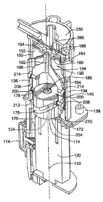
first and second channels can be axially separated with the first channel
proximate the
first end face 1372 of the cam and the second channel proximate the second end
face
1374, with both channels have a sinusoidal pattern. To engage the channels
1378, 1379,
the yoke 1390 has a first follower element 1396 extending inwardly from the
first leg
1392 and a second follower element 1398 extending inwardly from the second leg
1394.
The first and second follower elements 1396, 1398 are attached at different
locations
along the lengths of the respective first and second leg 1392, 1394 to
correspond to the
CA 02651035 2008-10-30
WO 2007/143273 PCT/US2007/066384
axially separated first and second channels 1378, 1379. When the cam 1370
rotates, it
drives the yoke 1390 via the follower elements 1396, 1398 from a position
wherein the
reciprocal element 1360 is fully retracted with respect to the chamber 1350 to
a position
wherein the reciprocal element if fully extended into the chamber 1350.
[0086] Referring to FIGS. 23 and 24, there is illustrated another embodiment
of a
handheld evacuation device 1400 having a user selectable pressure control
feature 1418.
In the illustrated embodiment, the nozzle 1406 of the evacuation device tapers
at one end
to form a generally square inlet opening 1408. The user selectable pressure
control
feature 1418 operates on the same principle described above but includes a
movable slide
1422 connected to and movable with respect to the nozzle 1406. A plurality of
varying
sized holes 1424 and 1426 are disposed along the length of the slide 1422.
Disposed
through the nozzle 1406 is an aperture 1428 which may be at least as large as
the largest
hole 1424 in the slide 1422. The slide 1422 is movable with respect to the
nozzle 1406 to
align the various holes 1424, 1426 with the aperture 1428 and thereby control
evacuation
pressure in the manner described above.
[0087] All references, including publications, patent applications, and
patents, cited
herein are hereby incorporated by reference to the same extent as if each
reference were
individually and specifically indicated to be incorporated by reference and
were set forth
in its entirety herein.
[0088] The use of the terms "a" and "an" and "the" and similar referents in
the
context of describing the invention (especially in the context of the
following claims) are
to be construed to cover both the singular and the plural, unless otherwise
indicated
herein or clearly contradicted by context. The terms "comprising," "having,"
"including," and "containing" are to be construed as open-ended terms (i.e.,
meaning
"including, but not limited to,") unless otherwise noted. Recitation of ranges
of values
herein are merely intended to serve as a shorthand method of referring
individually to
each separate value falling within the range, unless otherwise indicated
herein, and each
separate value is incorporated into the specification as if it were
individually recited
herein. All methods described herein can be performed in any suitable order
unless
21
CA 02651035 2008-10-30
WO 2007/143273 PCT/US2007/066384
otherwise indicated herein or otherwise clearly contradicted by context. The
use of any
and all examples, or exemplary language (e.g., "such as") provided herein, is
intended
merely to better illuminate the invention and does not pose a limitation on
the scope of
the invention unless otherwise claimed. No language in the specification
should be
construed as indicating any non-claimed element as essential to the practice
of the
invention.
[0089] Preferred embodiments of this invention are described herein, including
the
best mode known to the inventor(s) for carrying out the invention. Variations
of those
preferred embodiments may become apparent to those of ordinary skill in the
art upon
reading the foregoing description. The inventor(s) expect skilled artisans to
employ such
variations as appropriate, and the inventor(s) intend for the invention to be
practiced
otherwise than as specifically described herein. Accordingly, this invention
includes all
modifications and equivalents of the subject matter recited in the claims
appended hereto
as permitted by applicable law. Moreover, any combination of the above-
described
elements in all possible variations thereof is encompassed by the invention
unless
otherwise indicated herein or otherwise clearly contradicted by context.
22