Note: Descriptions are shown in the official language in which they were submitted.
CA 02651087 2013-11-29
1
Vehicle Cooling System With Directed Flows
FIELD OF THE INVENTION
[0001] The
present invention relates to cooling internal combustion engines.
More specifically, the present invention relates to cooling systems for
internal
combustion engines in vehicles.
BACKGROUND OF THE INVENTION
[0002]
Cooling systems for internal combustion engines in vehicles typically
comprise a water jacket and various galleries in the Internal combustion
engine
through which coolant, typically a mixture of water and ethylene glycol, is
circulated. The coolant is heated by the engine and averages temperatures in
the engine (which would otherwise vary significantly from place to place) and
is
then passed through a heat exchanger to dissipate waste heat to the
surrounding atmosphere.
After rejecting some heat through the heat
exchanger, the coolant is returned to the engine for another cycle.
[0003] In addition to the water jacket, galleries and heat exchanger
(typically
in the form of a radiator) modern cooling systems often include a variety of
other components such as heater cores, which are supplied with heated
coolant to warm the interior of the vehicle, and lubrication oil and/or
transmission oil coolers which are used to remove heat from the oils to
enhance their operating lifetimes and/or performance.
[0004]
Conventionally, these cooling systems typically consisted of one or
two loops through which the coolant circulated with minimal control, other
than
a thermostat, which restricted the flow of coolant through the radiator until
the
engine had reached a desired operating temperature, and a control valve which
would enable or disable the flow of coolant to the heater core depending upon
whether it was desired to supply heat to the interior of the vehicle.
[0005]
More sophisticated cooling systems, such as that taught in U.S.
Patent 6,668,764 to Henderson et al. have been proposed. The Henderson
system is intended for use with diesel engines and employs a multiport valve
in
conjunction with an electrically operated coolant pump to provide a cooling
system with several coolant circulation loops. By positioning the multipart
valve
CA 02651087 2013-11-29
in different positions and operating the electric water pump at different
speeds/capacities, different functions can be performed by the cooling system.
For example, at engine start up in cold ambient temperatures, all coolant flow
through the engine can be inhibited. Once a minimum engine temperature is
achieved, a flow of coolant can be provided to a passenger compartment
heater core. Once a higher engine operating temperature has been achieved,
or a specified temp has been exceeded, a flow of coolant can be provided to a
lubrication oil heater core to assist the lubrication oil in achieving a
desired
minimum operating temperature, etc.
[0006] While the cooling system taught in Henderson provides operating
advantages, it still suffers from some disadvantages in that it requires an
electrically operated coolant pump with a relatively high capacity to meet
worst
case cooling conditions. In zero flow, or restricted flow conditions, the
electric
coolant pump must be electrically shut down as such pumps typically cannot be
operated under zero flow conditions without damaging the pump. Further, such
pumps are more expensive to manufacture, control and maintain than are
mechanical coolant pumps and can be more subject to failures. Further, the
cooling system taught in Henderson requires both a lubrication oil cooling
heat
exchanger and a lubrication oil heating heat exchanger to be able to raise the
temperature of the lubricating oil of the engine to a desired minimum
operating
temperature and to then assist in cooling the lubricating oil.
[0007] It is desired to have a cooling system which provides for more
sophisticated heating and cooling strategies without requiring electrically
operated coolant circulation pumps or other expensive components.
SUMMARY OF THE INVENTION
[0008] It is an object of the present invention to provide a novel
coolant
system for internal combustion engines which obviates or mitigates at least
one
disadvantage of the prior art.
[0009] According to a first aspect of the present invention, there is
provided
a circulating coolant cooling system for an internal combustion engine,
comprising: a multifunction valve having a plurality of input ports and output
CA 02651087 2013-11-29
3
ports; a radiator connected between one of said inlet ports and one of said
outlet parts; a pump for pumping coolant, the pump connected between one of
said inlet ports and one of said outlet parts; a water jacket in the engine
block,
the water jacket connected between one of said inlet ports and one of said
outlet parts; a water jacket in the engine cylinder head, the water jacket
connected between one of said inlet ports and one of said outlet parts; a
heater
core for a heater in a passenger compartment, the heater core connected
between one of said inlet ports and one of said outlet parts; a degas bottle
to
capture and retain gases entrapped in the coolant, the degas bottle connected
between one of said inlet ports and one of said outlet parts; and a heat
exchanger for heating or cooling lubricating oil of the engine, the heat
exchanger connected between one of said inlet ports and one of said outlet
parts and wherein the multifunction valve interconnects the engine and cooling
system components operates to permit and inhibit direct flows of coolant as
necessary for thermal management of the engine.
[0olo] Preferably, in a first mode, the multifunction valve inhibits
coolant
flows in said cooling system, in a second mode the multifunction valve permits
the flow of coolant from the water pump to the water jacket in the engine
cylinder head, through the multifunction valve, and to the heater core. Also
preferably, in a third mode the multifunction valve also permits the flow of
coolant from the water pump to the water jacket in the engine block and
through the heat exchanger for the engine lubricating oil and in a fourth
mode,
the multifunction valve also permits a flow of heated coolant through the
degas
bottle. Also preferably, in a fifth mode, the multifunction valve also permits
the
flow of heated coolant through the radiator and a inhibits the flow of heated
coolant through the heat exchanger for the engine lubricating oil and permits
a
flow of cooled coolant through the heat exchanger for the engine lubricating
oil
and in a sixth mode, the multifunction valve inhibits the flow of coolant
through
the heater core.
[0011] Also preferably, additional or different cooling circuits/devices,
if
desired, can be provided with directed flows of coolant with the present
invention.
CA 02651087 2013-11-29
4
[0012] The
present invention provides an improved cooling system for
internal combustion engines. The cooling system provides directed flows of
heated or cooled coolant to various engine components and/or accessories as
needed. By providing directed flows, the overall coolant flow volume is
reduced
from that of conventional cooling systems, allowing for a smaller capacity
water
pump to be employed which results in a net energy savings for the engine.
Further, by reducing the overall coolant flow volume, the hoses and/or
galleries
required for the directed flows are reduced from those of conventional cooling
systems, providing a cost savings and a weight savings. Finally, by preferably
employing a mechanically driven impellor type water pump, the expense of an
electric water pump and its associated control circuitry can be avoided. The
direct flows are established by a multifunction valve which, in a preferred
implementation, comprises a two-plate valve wherein each plate is operated by
a wax motor, although other valve system and/or actuators, as will occur to
those of skill in the art, can also be employed.
BRIEF DESCRIPTION OF THE DRAWINGS
[0013]
Preferred embodiments of the present invention will now be
described, by way of example only, with reference to the attached Figures,
wherein:
Figure 1 shows a schematic representation of a cooling system in
accordance with the present invention, the cooling system being in a first
mode;
Figure 2 shows a schematic representation of a cooling system in
accordance with the present invention, the cooling system being in a second
mode;
Figure 3 shows a schematic representation of a cooling system in
accordance with the present invention, the cooling system being in a third
mode;
Figure 4 shows a schematic representation of a cooling system in
accordance with the present invention, the cooling system being in a fourth
mode;
CA 02651087 2013-11-29
Figure 5 shows a schematic representation of a cooling system in
accordance with the present invention, the cooling system being in a fifth
mode;
and
Figure 6 shows a schematic representation of a cooling system in
5 accordance with the present invention, the cooling system being in a
sixth
mode.
DETAILED DESCRIPTION OF THE INVENTION
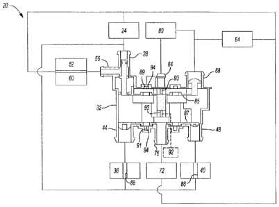
[0014] A cooling system in accordance with the present invention is
indicated generally at 20 in Figures 1 through 6. Cooling system 20 comprises
a water pump 24, which in a present embodiment of the invention is a
mechanical, impeller type, water pump whose output is somewhat less than the
output required from a water pump in a conventional cooling system for an
equivalent sized engine. For example, if a conventional cooling system
requires a water pump with an output of 4.7 litres per second at an engine
speed of 7700 RPM, it is contemplated that water pump 24 can have an output
of about 2.75 litres per second at 7700 RPM as with the directed flows of
coolant of the present invention, as described in more detail below, a reduced
flow rate (volume) of coolant can be employed, resulting in an overall energy
savings for the engine with the coolant system. In the particular example
discussed herein, the reduction in the required flow of coolant results in an
energy savings of approximately 1.37 kW (or almost two horsepower) with a
commensurate improvement in fuel economy and/or engine performance.
[0015] The output of water pump 24 is connected to both an input port 28
on
a multifunctional valve 32, described in more detail below, and to the engine
block 36 and cylinder head 40 of the engine. While it is preferred that
coolant
be separately circulated through engine block 36 and cylinder head 40, this is
not a limitation of the present invention and the present invention can be
employed with engines with a conventional integrated cooling jacket, albeit
with
a reduced cooling system efficiency.
CA 02651087 2013-11-29
6
[0016] The coolant outlet of engine block 36 is connected to an inlet
port 44
of valve 32 and the coolant outlet of cylinder head 40 is connected to another
inlet port 48 of valve 32.
[0017] An engine oil heat exchanger 52, which can operate to heat or
cool
engine oil is connected to an output port 56 of multifunction valve 32, as is
a
transmission oil heat exchanger 60 which can operate to heat or cool
transmission oil. While not illustrated, it is contemplated that engine oil
heat
exchanger 52 and transmission oil heat exchanger 60 can instead be
configured as separate directed flows if desired and, in this case,
transmission
oil heat exchanger 60 will be connected to another outlet port, not shown, on
multifunction valve 32. The coolant outlets of engine oil heat exchanger 52
and
transmission oil heat exchanger 60 are connected to the inlet of water pump 24
(as shown) or can alternatively be connected to (not shown) the inlet side of
a
radiator 64.
[0018] The inlet of radiator 64 is connected to an outlet port 68 of valve
32
and the outlet of radiator 64 is connected to the inlet of water pump 24 and
to a
passenger compartment heater core 72 and the outlet of heater core 72 is
connected to an inlet port 76 of valve 32.
[0019] A coolant degas bottle 80 is also connected to outlet port 68 and
is
further connected to an inlet port 84 of valve 32 and degas bottle 80 operates
to remove entrapped gasses from the coolant circulating through system 20.
While in the illustrated embodiment degas bottle 80 is illustrated as a
separate
component, in some coolant systems the degas bottle comprises an end tank
on the radiator and such systems are intended to fall within the term degas
bottle, as used herein.
[0020] Multifunction valve 32 operates, as described below, to
appropriately
direct flows of coolant through various components of cooling system 20 as
needed. In a present embodiment of the invention, multifunction valve 32
includes two plates 85, 87 which move to open, close and interconnect the
inlet
and outlet ports of valve 32 to permit or inhibit the flows of coolant. In the
present embodiment, the plates 85, 87 of valve 32 are operated by a wax
CA 02651087 2013-11-29
7
motor, although any other suitable operating mechanism can be employed, as
described below.
[0021] Wax motors comprise wax filled cylinders with moveable pistons
mounted therein such that, when heated, the wax expands extending the piston
to operate a device such as the plates of valve 32. When cooled, the wax
contracts, either drawing the piston back into the cylinder (and retracting
the
valve plate) or allowing the piston to be urged back into the cylinder by a
biasing spring. Wax motors are commonly used in thermostats for cooling
systems, amongst other uses, and can be directly controlled by the
temperature of the coolant and can also be electronically controlled by
operating an electric heater adjacent the cylinder to heat the wax in the
absence of sufficient temperature of the coolant.
[0022] In the preferred embodiment of the present invention, the wax
motors
89, 91 operating the plates 85, 87 in valve 32 are immersed in the coolant and
are also equipped with an electric heater 94 to allow the operation of the
plates
to be electrically overridden if desired.
[0023] While the present embodiment employs a dual plate, wax motor
operated valve as multifunction valve 32, it will be apparent to those of
skill in
the art that the present invention is not so limited and any suitable valve
mechanism can be employed as desired and any suitable operating
mechanism, including microprocessor controlled electronic valves or an
electric
motor 92 with gear driver for two threaded shafts 93, 95 that rotate and in
turn
allow the valve plates to move relative to each other via threaded components
integrated into each plate. The alternative electric motor 92 and shafts 93,
95
are shown in hidden line representation.
[0024] As mentioned above, in the present invention directed flows of
coolant are provided or inhibited to various cooling system components as
required. In Figure 1, system 20 is shown in a start up configuration, for
cooler
ambient temperatures wherein no coolant flows are provided and water pump
24 is effectively deadheaded.
[0025] After the engine is started and the cylinder head 40 begins to
warm,
valve 32 connects inlet port 48 to outlet port 76. This results, as shown in
CA 02651087 2013-11-29
8
Figure 2, in a directed flow of coolant from water pump 24 to a water jacket
86
of cylinder head 40, where it is heated, and then through heater core 72, to
permit warming of the passenger compartment of the vehicle and then back to
the inlet of water pump 24. In Figure 2, the flow of cool coolant is indicated
in
solid medium-weight line while the flow of hot coolant (between cylinder head
40 and heater core 72) is indicated in dashed heavy line, while coolant paths
with no flow of coolant are indicated in thin line.
[0026] As illustrated in Figure 3, as the engine continues to warm, a
further
directed flow is created when valve 32 connects inlet port 44 to outlet port
56
also directing coolant from water pump 24 through a water jacket 88 of engine
block 36, where it is warmed, and through engine oil heat exchanger 52 and
transmission oil heat exchanger 60, where the warm coolant heats the oils and
is, in turn, cooled, and then returns back to the inlet of water pump 24. As
before, the flows of cool coolant are indicated in solid medium-weight line
while
the flows of hot coolant are indicated in dashed heavy line. Water jacket 88
is
separate from water jacket 86.
[0027] By providing a directed flow of coolant to heater core 72,
virtually any
desired coolant flow rate can be achieved through heater core 72 in contrast
to
conventional bypass designs. Therefore, if desired, any flow rate up to the
entire capacity of water pump 24 can be provided to heater core 72 for
increased passenger comfort.
[0028] Figure 4 shows the next directed flow which occurs, as the engine
warms to approach its expected operating temperature. As shown, valve 32
partially opens outlet port 68 to allow flow of heated coolant through degas
bottle 80 to inlet port 84, which is also now open, and then to heater core
72.
As the degas bottle 80 typically contains some volume of coolant, in the
present invention circulation of coolant through degas bottle 80 is inhibited
until
this point to allow the other directed flows to make any needed use of warmed
coolant.
[0029] One of the advantages of the present invention is that multifunction
valve 32 can modulate flows of coolant between maximum and minimum flow
CA 02651087 2013-11-29
=
9
rates as desired, unlike prior art systems wherein the flows were either
enabled
or inhibited.
[0030] As
the engine achieves its normal expected operating temperature,
valve 32 fully opens outlet port 68 as shown in Figure 5 to allow coolant
heated
by cylinder head 40 and engine block 36 to flow through radiator 64 where it
is
cooled and returned to the inlet of water pump 24. Also, inlet 28 is opened
and
outlet port 56 is connected to it, rather than to inlet port 44, such that
cool
coolant is supplied to engine oil heat exchanger 52 and to transmission oil
heat
exchanger 60 to commence oil cooling.
[0031] If the operating temperature of the engine begins to approach an
upper level of its permitted range, system 20 can be configured to close
outlet
76, stopping coolant flow through heater core 72 and instead adding that
coolant flow to the coolant flow passing through radiator 64.
[0032] By
directing separate flows of coolant, as necessary and/or
appropriate, for different operating conditions of the engine, better thermal
management of the engine can be achieved. Further, because the directed
flows are sized for the particular heat transfer needs, the hoses and
galleries
for the flows are generally smaller than those needed for conventional cooling
systems wherein one, or perhaps two, flows encompass all of the circulating
coolant.
[0033]
Also, water pump 24 can be smaller than the water pumps used in
conventional cooling systems as the total coolant flow volume through system
20 can be smaller than the flow volumes through conventional cooling systems.
Also, as water pump 24 is preferably an impellor type pump driven by the
engine, the extra expense of the electric water pump, required by other
cooling
systems, can be avoided as water pump 24 can be deadheaded when no flow
is required.
[0034]
Another advantage of the present invention over other cooling
systems is that separate heat exchangers are not required to heat and cool the
engine oil as the appropriate flow of either heated coolant or cooled coolant
can
be provided to heat exchanger 52 to either heat or cool the engine lubricating
oil, as required. Similarly, separate heat exchangers are not required to heat
CA 02651087 2013-11-29
,
- 10
and cool the transmission oil as the appropriate flow of either heated coolant
or
cooled coolant can be provided to heat exchanger 60 to either heat or cool the
engine lubricating oil, as required.
[0035] While the description above only discusses radiators,
heater cores,
degas bottles, cylinder heads, engine blocks and heat exchangers for
lubrication oil and/or transmission oil, the present invention is not so
limited and
any additional, or alternative, coolant circuits/devices can also be employed
with the present invention. For example, throttle body heaters, EGR valve
coolers, fuel heating heat exchangers, additional heater cores, brake system
coolers or any other coolant device can be provided with an appropriate direct
flow of coolant.
[0036] As will now be apparent, the present invention provides an
improved
cooling system for internal combustion engines. The cooling system provides
directed flows of heated or cooled coolant to various engine components and/or
accessories as needed. By providing directed flows, the overall coolant flow
volume is reduced from that of conventional cooling systems, allowing for a
smaller capacity water pump to be employed which results in a net energy
savings for the engine. Further, by reducing the overall coolant flow volume,
the hoses and/or galleries required for the directed flows are reduced from
those of conventional cooling systems, providing a cost savings and a weight
savings. The resulting reduced overall flow rate requirements and/or smaller
water pump results in an energy savings compared to conventional cooling
systems. Also, by inhibiting the flow of coolant during start up conditions,
the
engine can achieve desired operating temperatures more quickly, allowing for
reduced emissions and enhanced fuel economy. Finally, by preferably
employing a mechanically driven impellor type water pump, the expense of an
electric water pump and its associated control circuitry can be avoided. The
direct flows are established by a multifunction valve which, in a preferred
implementation, comprises a two-plate valve wherein each plate is operated by
a wax motor or by any suitable electric motor and control system.
[0037] The above-described embodiments of the invention are
intended to
be examples of the present invention and alterations and modifications may be
CA 02651087 2013-11-29
11
effected thereto, by those of skill in the art, without departing from the
scope of
the invention which is defined solely by the claims appended hereto.