Note: Descriptions are shown in the official language in which they were submitted.
CA 02651108 2008-11-03
WO 2007/130516 PCT/US2007/010737
DO'WNHOLE MICRO MAGNETIC RESONANCE ANALYZER
Background
Field of Invention
The present invention pertains.to downhole nuclear magnetic resonance (NMR)
tools
for use in a wellbore, particularly small-scale downhole NMR tools.
Related Art
Downhole NMR tools are commonly used, in oil and gas exploration, for example,
to
ascertain or infer properties of the subsurface formations encountered by a
wellbore.
Downhole NMR tools may be used while drilling the wellbore, or may be run into
the
wellbore after drilling, for example, on a wireline. Various reservoir fluid
properties can be
measured using a downhole NMR tool. Measurements can be made on reservoir
fluids in the
formation, or measurements can be made on a fluid sample withdrawn from the
formation or
wellbore. The NMR tool can be a stand-alone tool or may be incorporated as a
module in a
fluid sampling tool such as that disclosed in U.S. Patent No. 6,346,813 B1
issued to
Kleinberg. An example of a formation fluid tester tool is the Modular
Formation Dynamics
Testing tool marketed under the trade name of MDTrm by Schlumberger Technology
Corp.
(Houston, TX).
A downhole NMR tool generally includes a magnet that produces a static
magnetic
field over the volume of the fluid sample. The NMR tool also includes a coil
or antenna to
produce radio frequency (RF) pulses. The magnetic dipole moment of the RF
antenna is
substantially perpendicular to the magnetic dipole moment of the static
magnetic field. In
addition, the NMR. tool may include one or more gradient coils.
The static field of a downhole NMR tool is generally too inhomogeneous to
allow
NMR spectroscopy to be performed. The inhomogenieties are attributed to
variations in the
magnetic material comprising the magnets and the magnet configuration. Thus,
the static
magnetic field inhomogenieties over the sample volume are to too large to
perform NMR
spectroscopy, but is generally acceptable for conventional NMR measurements
such as
relaxation times and diffusion.
CA 02651108 2012-07-18
79350-266
2
Summary
A downhole micro MR analyzer for use in a wellbore, having a micro
sample tube, a micro RE coil in close proximity to the micro sample tube, and
one or more magnets disposed about the micro sample tube is disclosed. The
micro
MR analyzer can be used for nuclear magnetic resonance or electron spin
resonance
experiments to ascertain formation properties and chemical compositions.
In one particular aspect of the invention, there is provided a downhole
micro MR analyzer comprising: a micro sample tube connected to a downhole
wellbore sampling tube, the micro sample tube, the micro sample tube comprises
a
substrate having a passageway formed therein for transporting a reservoir
fluid; a
micro RF coil in close proximity to the micro sample tube wherein at least a
portion of
the coil is etched directly onto the micro sample tube; and one or more
magnets
micro-fabricated by constructing at least one of the magnets directly on the
substrate
comprising the micro sample tube, the one or more magnets generating a
magnetic
field into the micro sample tube.
There is also provided a downhole micro MR analyzer system
comprising: a micro RE coil; a micro-strip line with a first conductive trace
on a
dielectric material mounted onto a second conductive trace; a slit through the
micro
strip line forming a micro sample tube; and a magnet disposed about the micro
sample tube, with the micro sample tube connected to a downhole wellbore
sampling
tool in order to transport reservoir fluid through the analyzer system.
Another aspect of the invention provides a method to perform a
MR experiment in a wellbore, comprising: sampling a reservoir fluid with a
downhole
wellbore sampling device; transporting the reservoir fluid to a downhole micro
MR analyzer in the wellbore, the downhole micro MR analyzer comprising: a
micro
sample tube; a micro RE coil in close proximity to the micro sample tube, the
micro
RE coil etched on a printed circuit board and attached to the micro sample
tube; and
CA 02651108 2012-07-18
'
' 79350-266
2a
one or more magnets disposed about the micro sample tube in order to generate
a
magnetic field within the micro sample tube; obtaining a portion of the
reservoir
fluid in the micro sample tube; polarizing the portion of the reservoir fluid
with the
one or more magnets; irradiating the portion of the reservoir fluid sample
with
RF signal from the micro RF coil; and measuring the MR response from the
portion of
the reservoir fluid in order to ascertain properties of the wellbore,
formation about the
wellbore or the fluid sample.
Brief Description of Drawings
Figure 1 shows one embodiment of a micro NMR analyzer constructed
in accordance with the present invention.
Figure 2 shows one embodiment of a sample delivery half channel that
may be used in the micro NMR analyzer of Figure 1.
Figure 3 shows one embodiment by which the pre-polarization length
that may be used in the micro NMR analyzer of Figure 1.
Figure 4 shows one embodiment of a spiral coil that may be used in the
micro NMR analyzer of Figure 1.
Figure 5 shows one embodiment of a Helmholtz coil that may be used
in the micro NMR analyzer of Figure 1.
Figure 6 shows one embodiment of a solenoid coil that may be used in
the micro NMR analyzer of Figure 1.
Figure 7 shows one embodiment of a slitted micro strip that may be
used in the micro NMR analyzer of Figure 1.
Figure 8 shows a configuration that may be used in the micro
NMR analyzer of Figure 1 to produce a Z-axis (dBz/dZ) gradient coil.
CA 02651108 2012-07-18
,
79350-266
2b
Figure 9 shows a configuration that may be used in the micro
NMR analyzer of Figure 1 to produce a Y-axis (dBz/dY) gradient coil.
Figure 10 shows a configuration that may be used in the micro
NMR analyzer of Figure 1 to produce an X-axis (dBz/dX) gradient coil.
CA 02651108 2008-11-03
WO 2007/130516 PCT/US2007/010737
3
Figure 11 shows an embodiment of the micro NMR analyzer of Figure 1 using a
permanent magnet.
Figure 12 shows an embodiment of the micro NMR analyzer of Figure 1 using an
electromagnet.
Detailed Description
This invention relates to a lab-on-a-chip/micro magnetic resonance analyzer
and
method of using same. A micro magnetic resonance analyzer (micro MR analyzer)
can
measure nuclear spins or electron spins. One that measures nuclear spins is
referred to as a
micro NMR analyzer, and one that measures electron spins is referred to as a
micro ESR
analyzer. Although the discussion below is directed to a micro NMR analyzer,
it is equally
applicable to a micro ESR analyzer.
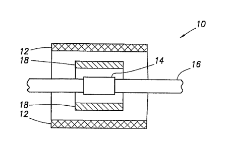
As shown in Figure 1, the micro NMR analyzer 10 has a micro or macro sized
magnet
12, a micro RF coil 14, a micro sample tube 16, and optionally a micro
gradient coil 18. The
micro RF coil antenna 14 (coil diameter <1 mm) may be built using micro-
fabrication
techniques. Since the micro RF coil 14 (or probe) is small, the NMR sensitive
region is also
small and the static magnetic field inhomogeneity will be small over this
region. As a result,
it is possible to make NMR measurements using the micro NMR analyzer 10 even
though the
static magnetic field is non-homogeneous when considered over larger
dimensions. Because
the electrical power required to excite the NMR spins with the micro RF coil
14 is small, a
miniaturized magnetic resonance spectrometer can be built. The gradient coils
18 can also be
constructed using micro-fabrication techniques, including electroplating
technology. Micro-
fabrication techniques are effective in establishing accurate geometries and
good mechanical
stability for the tool components.
Figure 1 shows a micro NMR analyzer 10 for downhole fluid analysis constructed
on
a small (micro) scale relative to existing NMR analysis devices. The micro NMR
analyzer 10
is connected to supporting electronics (not shown) for excitation and data
acquisition. The
supporting electronics may be different for a micro ESR analyzer, but serves
effectively the
same purpose. The micro NMR analyzer 10 uses very small fluid sample volumes
on .which
to make measurements to obtain various fluid properties like viscosity, spin-
lattice relaxation
time (Ti), spin-spin relaxation time (T2), molecular diffusion (D), molecular
composition,
hydrogen index (HI), and water saturation (Sw). The micro NMR analyzer 10 can
be used
CA 02651108 2008-11-03
WO 2007/130516 PCT/US2007/010737
4
alone or in conjunction with the Schlumberger Modular Dynamics Tester (MDT)
tool or a
similar sampling tool.
Figure 2 shows in part one embodiment of the sample tube 16. In this
embodiment,
sample tube 16 comprises two pieces of non-conductive material such as glass,
ceramic, or a
polymer. Figure 2 shows one of the two pieces. The two pieces have channels 20
cut into
them, for example, by etching techniques. When the two pieces are brought
together, the two
channels 20 align to form a passageway with a desired cross-sectional shape.
The cross-
sectional dimensions of the sample Aube 16 help determine the flow rate and is
a design
parameter available to the system designer. Because micro-fabrication
techniques are used,
the path and cross-sectional area of the sample tube 16 can be well-controlled
and allows for
complicated design choices. More than two pieces can be used to form the
sample tube 16.
Alternatively, a capillary tube can be used as a sample tube 16.
To pre-polarize the fluid before it enters the measurement volume, an
elongated
sample delivery channel 22 can be added to the sample tube 16. The sample
delivery channel
22 can be a straight section of channel as described above, or is preferably a
channel
traversing a winding or helical path in the vicinity of the measurement
volume, as shown in
Figure 3. The latter approach reduces the size of the magnet needed to create
the pre-
polarization. Depending upon the pre-polarizing path length, the NMR
measurement can be
done at a slow flow rate or in a mode in which the fluid is stopped (stopped
mode).
In addition to generating Bo for NMR measurement, a rather long section of DC
(i.e.,
static) magnetic field is needed for pre-polarization. It is preferable to
have as large a pre-
polarizing magnetic field as possible. The homogeneity requirements, however,
are not as
stringent in the pre-polarization region as they are in the NMR measurement
volume, as
discussed further below.
The NMR signal-to-noise ratio is, among other factors, proportional to the 7/4
power
of Bo. Thus it is desirable to use as large a Bo field as possible in the
micro NMR analyzer
10. A first parameter of interest in the magnet design is the strength of the
magnet 12, which
should be as strong as possible. This is achieved primarily by keeping the
sample as close to
=
the magnet 12 as possible. A second parameter is the homogeneity of the
magnetic field.
The field should be made as homogeneous as possible. While a larger magnetic
field is
CA 02651108 2008-11-03
WO 2007/130516 PCT/US2007/010737
desired, one must always be aware that space limitations and other geometric
constraints, as
well as temperature considerations, can limit magnet selection.
The magnetic field can be generated by a direct current circulating in a coil,
or by
using a permanent magnetic material such as samarium cobalt (SmCo). For a
given magnet
size, the magnetic field strength of a superconducting electromagnet is larger
than that of a
permanent magnet, which in turn is larger than the magnetic field of an
electromagnet made
with non-superconducting wires. All three types of magnet designs are feasible
and within
the scope of the present invention. The choice depends on various factors such
as the
complexity of the instrumentation and the expense. For example, a
superconducting magnet
can generate the largest and most homogeneous magnetic field, but requires
cryogenics and
maintenance, while a permanent magnet is carefree, but variations in material
may lead to
somewhat inhomogeneous fields that for some applications would compromise the
tool's
performance.
Preferred embodiments use permanent magnets 12. Using the micro-fabrication
approach, the magnets 12 can be deposited directly on the "chip" or substrate
material 13
comprising the sample tube 16. Using the macro approach, a permanent magnet 12
can be
made easily. Two parallel magnets can form a reasonably homogeneous magnetic
field, as is
known in the art. The field produced by the permanent magnets 12 has
variations caused by
variations in the magnetic material. Those variations in the field are
proportional to the size
of the smaller blocks used to construct the magnet 12. However, the NMR
measurement
volume, which is proportional to the sample size, is very small and can be
made to be much
smaller than the relevant block size. Thus it is possible to perform NMR
measurements in a
substantially homogeneous region. Since the sample tube 16 and the micro RF
coils 14 can
be made very small, the two permanent magnets 12 can be brought very close to
each other,
thereby increasing the magnetic field permeating the sample volume. The small
size of the
NMR sensitive volume helps with the Bo homogeneity requirement, thus allowing
the use of
virtually any method of generating a static magnetic field. In another
embodiment, more than
two magnets 12 can be used to produce Bo. It is well known in the art that
arranging six or
more magnets in a particular field orientation can form a cylindrically shaped
homogeneous
magnetic field that is very well suited for this application.
Various embodiments of micro 12F coils 14 may be used in the present
invention.
While preferred frequencies are in the RF range, the invention is not limited
to those
CA 02651108 2008-11-03
WO 2007/130516 PCT/US2007/010737
6
frequencies. The planar nature of some of these coils is ideal in space-
constrained locations.
In one embodiment, the invention comprises a Helmholtz coil, that is, having
two coils
arranged with their planes parallel and separated a distance equal to the
diameter of the coils.
This coil arrangement produces a very homogeneous magnetic field in the space
between the
two coils and is ideal for the current application. For space reduction and
ease of construction
by micro-fabrication techniques, the two coils 14 can be made of spiral shape
as shown in
Figure 4. The spiral portion of the coil 14 can be etched on a printed circuit
board and
attached to the sample tube 16, but a preferred embodiment is to etch the
coils 14 directly
onto the sample tube 16. The thickness and width of the conductive material
(e.g., copper)
comprising the spiral portion can be small (e.g., <1mm). The two coils 14 may
be placed on
opposite sides of the sample tube 16, as shown schematically in Figure 5. The
coil
diameter/separation distance should be chosen so as to produce a homogeneous
field
throughout the sample volume, and preferably in the closest possible proximity
to the sample
tube 16.
A solenoid-shaped micro coil 14 is shown in Figure 6 and may be used in the
present
invention. Similar to the Helmholtz coil embodiment described above, the
diameter of the
solenoid RF coil 14 may be relatively small (e.g., <1mm). The coil 14 may be
wound around
the sample tube 16, but preferably is micro-fabricated with the winding
disposed directly on
the sample tube 16. This allows more control on the field homogeneity and
helps reduce
acoustic ringing. This embodiment is particularly useful for a capillary tube
used as a sample
tube 16. Again, the coil 14 is preferably placed in the closest possible
proximity to the
sample volume. Such a configuration produces a substantially homogenous field
within the
sample volume and optimizes the "filling factor" (percentage of coil interior
occupied by the
sample) of the coil 14.
A further embodiment of a micro RF coil 14 comprises a conventional micro-
strip line
24 having a first conductive trace 26 on top of a dielectric material 28
mounted onto a ground
plane 30 (a second conductive trace). The impedance is determined by the width
of the first
conductive trace 26, the dielectric constant of the dielectric material 28,
and the separation
distance between the two conductive traces 26, 30. The conventional micro
strip line 24 can
= be machined or etched to form a small (e.g., << one wavelength) slit 32
through the micro
strip 24 (see Figure 7). The passageway created by the slit 32 forms the
sample tube 16. As
before, this embodiment may be fabricated using micro-fabrication techniques.
CA 02651108 2008-11-03
WO 2007/130516 PCT/US2007/010737
7
Gradient coils 18 can be used to study diffusion and for imaging. Because of
the
planar nature of the gradient coils 18, they can also be constructed using
micro-fabrication
techniques, and therefore do not occupy too much space. Self-diffusion studies
on fluid
samples require a gradient in only one direction. Various coil arrangements
producing
various gradients are shown in Figures 8, 9, and 10. Other more sophisticated
measurements
such as imaging may require other, more complicated gradients. Combinations of
the various
coil arrangements described above may be used to provide the more complicated
gradients.
The embodiment shown in Figure 11 comprises two opposing permanent magnets 12
positioned on either side of the sample tube 16. The magnets 12 are either
deposited on the
faces of the chip or they can be macro permanent magnets placed near those
surfaces. A
permeable magnetic pole piece (see Figure 12) can also be used to focus the
field and thereby
increase the homogeneity of the magnet. The magnetic field strength depends on
the
characteristics of the magnetic material and the dimensions of the magnet.
This configuration
may be used to perform NMR studies during flow and also at stopped mode. The
magnet 12
is longer than the micro RF coil 14 to allow pre-polarization of the spins
before detection.
The micro RF coils 14 are micro-fabricated on the two faces of the chip that
are normal to the
magnets 12. Permeable magnetic materials that are operable in the RF range can
also be used
enhance the magnetic field of the micro RF coils 14. Permeable magnetic
materials can also
be used to enhance the performance of gradient coils 18.
The embodiment shown in Figure 12 uses electromagnets 34. A static Bo field is
focused on the sensing (measurement) volume using permeable magnetic rods 36
that form a
C-type magnet. The design as shown performs the NMR measurement in stopped
mode
because there is no pre-polarization of spins for flowing spins. However, pre-
polarization can
be added. The B1 field is provided by a micro RF coil 14 or, alternatively,
Helmholtz-type
coils can be fabricated on the side faces.
The two- and three-dimensional NMR techniques described above can be used to
characterize reservoir fluid properties using NMR logging tools. Typical NMR
molecular
dynamic parameters such as Ti, T2, and D can be measured with the present
invention. In
addition, the chemical shift or NMR spectroscopy information of the reservoir
fluid can be
obtained using the present invention, as can the velocity profile of the
flowing fluid inside the
sample tube.
CA 02651108 2008-11-03
WO 2007/130516 PCT/US2007/010737
8
While protons are normally the spins of interest in NMR experiments, other
spins may
be used. For example, certain isotopes of carbon, phosphorus, or fluorine have
spins that can
produce an NMR response. The present invention can be adapted to perform NMR
experiments on any sample containing spins capable of producing an NMR
response.
Electron spin resonance (ESR, also known as electron paramagnetic resonance,
EPR)
occurs, for example, when an atom has an unpaired electron. It may also occur
for
paramagnetic compounds such as oxygen (02) and free radicals such as a
chlorine atom.
Certain metals, such as vanadium, also combine with organic compounds such
that unpaired
electrons stably exist. Magnetic resonance experiments can be performed on
samples
exhibiting ESR, and the present invention allows such experiments to be
performed
downhole.
Multiple micro NMR analyzers can be used simultaneously or sequentially. This
allows investigation of different spins or compositions and yields multiple
data points. This
is in contrast to existing downhole NMR tools for which it is impractical to
use one NMR
tool in proximity to other NMR tools.
The present invention can be fabricated using micro fabrication techniques
with the
entire apparatus constructed on a chip 13. Alternatively, a portion of the
apparatus can be
made on chip 13. This is particularly so for the sample tube 16 and micro RF
coils 14. The
magnets 12 may or may not be fabricated directly on the chip 13.
While the invention has been described with respect to a limited number of
embodiments, those skilled in the art, having benefit of this disclosure, will
appreciate that
other embodiments can be envisioned that do not depart from the scope of the
invention as
disclosed herein. Accordingly, the scope of the invention shall be limited
only by the
attached claims.