Note: Descriptions are shown in the official language in which they were submitted.
CA 02651211 2011-11-24
WO 2007/130128 PCT/US2006/042604
LABEL SHEET ASSEMBLY, APPLICATION KIT AND
METHOD OF USING THE SAME
TECHNICAL FIELD
[0002] The present invention generally relates to labels and, more
particularly,
relates to an improved index divider label sheet assembly, method of
application, and
an application kit including the label sheet assembly.
BACKGROUND
[0003] Various systems for indexing documents utilizing dividers and labels
are
available. In a typical system, documents are separated by divider sheets to
aid with
identification of the documents. The dividers often include tabs having
indicia thereon
for helping a user to locate and organize documents.
[0004] While such systems may have been satisfactory for helping to index
groups
of documents, the task of applying identifying indicia or identifying labels
to the
divider tabs is time consuming, clumsy and subject to error. In many systems,
tab
attachable labels have been employed to help overcome such difficulties.
Typically,
during application the individual labels are separated from one another and
then
attached individually to corresponding ones of the divider tabs. In the course
of
individually applying the labels, they are often not applied evenly, or
properly aligned
with the divider sheet tabs. Even though the use of this type of attachable
labels may
have permitted the divider tabs to have identifying indicia, such labels have
not been
convenient to use.
[0005] Previous patents have taught various remedies for overcoming these
shortcomings when applying tabs to index dividers. One previous example
includes
1
CA 02651211 2008-11-04
WO 2007/130128 PCT/US2006/042604
the use of precut labels attached to carrier strips that are in turn secured
to a backing
sheet. The precut labels are spaced apart on the carrier strips to align
substantially on
the tabs on the divider sheets. The user can separate a carrier strip and
precut labels
affixed thereto from the backing sheet, place and align the carrier strip
across the
divider sheet such that the precut labels are placed on the tabs of the
divider sheets.
The carrier sheet is then pulled upwardly and away from the divider sheet such
that
the precut labels separate from the carrier strip and remain on the divider's
tabs. This
system, while an improvement in certain respects over the prior art, has the
disadvantage that the strips are typically flimsy and difficult to properly
align.
Additionally, the carrier strip can be sticky and thus may stick to unwanted
surfaces.
[00061 Another remedy for the shortcomings faced when applying tabs to index
dividers includes the use of a facestock adhered with releasable adhesive to a
liner
sheet. Die cut lines are made through the facestock to define labels to be
aligned with
either one or more sets of dividers or sets of file folders. Different pattern
die cut
lines are made through the liner sheet so that a strip can be removed directly
from
behind the labels, exposing the adhesive side of the labels. The labels are
temporarily
held onto the remainder of the facestock by small ties. After alignment and
adhesion
to the dividers, the facestock is then pulled upwardly and away from the
divider sheet.
This movement breaks the ties, leaving just the labels on the substrate. This
system
while a further improvement requires the use of ties to maintain the labels
during
alignment of the labels with the dividers. The ties may prove to be a
disadvantage in
that they may leave rough edges about the perimeter of the label where the
ties have
been broken during removal of the label sheet.
[00071 Another shortcoming of previous patents is that after removal of the
strip
and application of the labels onto the substrate, the sheet is no longer
printable. In
one instance the sheet is an irregular size after the strip is removed.
Irregular sheets
may have difficulty passing through printers or copiers-. In another instance,
after the
labels have been applied to the substrate, the sheet has holes where the
labels were.
The holes may impart unwanted flexibility in the sheet or may provide catch
points
causing difficulty in passing through a printer or copier. Further removal of
the labels
and liner exposes adhesive on the remainder of the sheet, which may cause the
sheet
to adhere to the feed mechanism in a printer or copier. Thus, since printing
after label
2
CA 02651211 2008-11-04
WO 2007/130128 PCT/US2006/042604
removal may be problematic, all the labels should be printed in a single
printing step.
Any unprinted labels could not be printed in a second pass through the printer
or
copier and would have to be used unprinted or wasted.
[0008] Therefore it would be highly desirable to have a new and improved index
divider label applicator construction, method of application, and an alignment
kit and
method of using the same to facilitate the application of tab labels in a
fast, efficient,
and accurately aligned manner. Such a new and improved label and method should
enable a user to apply all of the divider tab labels substantially
simultaneously.
Furthermore, other desirable features and characteristics of the present
invention will
become apparent from the subsequent detailed description and the appended
claims,
taken in conjunction with the accompanying drawings and the foregoing
technical
field and background.
BRIEF SUMMARY
[0009] There has now been developed a new label sheet assembly and assembly
kit.
In one embodiment, the label sheet assembly comprises a label facestock and a
carrier
strip. The label facestock sheet is removably affixed with adhesive to the
front face of
the carrier strip in an overlying aligned manner. The label facestock sheet
includes a
plurality of cut lines defining at least a perimeter of a plurality of labels
spaced from
one another in an offset manner that substantially corresponds to a set of
staggered
tabs extending outwardly from a stacked group of tabbed members having a
predefined arrangement of tab. The carrier strip is defined by a plurality of
cut edges
having substantially the same shape as a portion of the perimeters of the
facestock
labels, but with slightly smaller dimensions as its respective plurality of
labels. The
carrier strip overlaps at least a portion of each of the plurality of labels
defining an
overlapping portion. The overlapping portion is adapted to expose a back
adhesive
surface of each,of the labels in the plurality of labels when the carrier
strip is in a
separated position.
[0010] In a further embodiment, still by way of example only, there is
provided a
label sheet assembly, comprising a liner sheet, a carrier sheet having a back
face and a
front face, and a label facestock sheet. The carrier sheet back face is
removably
affixed to the front face of the liner sheet in an overlying aligned manner.
The label
3
CA 02651211 2008-11-04
WO 2007/130128 PCT/US2006/042604
facestock sheet is removably affixed with adhesive to the front face of the
carrier
sheet in an overlying aligned manner. The label facestock sheet includes a
plurality
of cut lines extending through the label facestock sheet but not through the
carrier
sheet. The plurality of cut lines define at least a perimeter of a plurality
of labels
spaced from one another in an offset manner that substantially corresponds to
a set of
staggered tabs extending outwardly from a stacked group of tabbed members
having a
predefined arrangement of tabs. The liner sheet, the carrier sheet .and the
label
facestock sheet form a laminate construction sheet. The carrier sheet includes
a
plurality of cut lines extending through the carrier sheet but not through the
label
facestock sheet or the liner sheet and having substantially the same shape as
a portion
of the perimeters of the labels, but with slightly smaller dimensions as its
respective
the label to define a plurality of carrier strips. Each of the carrier strips
is capable of
being removed from the liner sheet to expose an overlap of a portion of the
label on
the carrier strip and a back adhesive surface of each of the labels such that
the carrier
strip can assist the user in positioning the labels at desired locations on at
least one
surface and adhered thereto with the adhesive. The at least one surface
includes the
staggered tabs of the stacked group of tabbed members.
[00111 In still a further embodiment, and still by way of example only, there
is
provided a label sheet assembly, comprising a liner sheet, a carrier sheet
removably
attached to the liner sheet and a label facestock sheet. The carrier sheet
includes at
least one weakened separation line defining at least in part a carrier strip.
The label
facestock sheet is removably attached to the carrier sheet. The label
facestock sheet
includes at least one weakened separation line defining at least in part
perimeters of a
plurality of aligned labels. The carrier strip is in an attached position on
the liner
sheet and constructed so as to be positionable in an alternative removed
position when
removed from the liner sheet. Portions of the bottom surfaces of the labels
are
exposed when the carrier strip is in the removed position. At least a portion
of the
perimeter of the labels is overlapping the carrier strip to define a carrier
strip overlap
portion and reversibly adhered thereto such that the labels are adapted to be
applied in
an aligned applied position to a plurality of staggered tabs. The assembly
further
includes an adhesive means for adhering the carrier sheet to the facestock
sheet when
in the attached position and for also adhering the labels to the staggered
tabs when the
labels are in the applied position.
4
CA 02651211 2008-11-04
WO 2007/130128 PCT/US2006/042604
[0012] In still yet a further embodiment, and still by way of example only,
there is
provided an index divider label application kit comprising An index divider
label
application kit comprising at least one set of divider sheets, at least one
pressure
sensitive label sheet assembly including at least one carrier strip, and an
alignment
guide for aligning the at least one carrier strip with the divider tabs on the
set of
divider sheets. The at least one set of divider sheets, each having outwardly
extending
divider tabs vertically offset from one another in a predetermined arrangement
when
the divider sheets overlay one another. The at least one pressure sensitive
label sheet
assembly includes at least one carrier strip, and a label facestock sheet, the
at least one
carrier strip and the label facestock sheet removably secured together by a
layer of a
pressure sensitive adhesive material. The label facestock sheet includes a
plurality of
cut lines defining a perimeter of a plurality of spaced apart precut labels
aligned in an
alignment configuration that corresponds substantially to the predetermined
arrangement of the divider tabs extending outward from the divider sheets. The
at
least one carrier strip includes a plurality of cut edges having substantially
the same
shape as a portion of the perimeters of the facestock labels, but with
slightly smaller
dimensions as its respective the label, such that when the at least one
carrier strip
overlies the divider tabs on the set of divider sheets, each of the precut
labels is
located on top of a respective divider tab. The precut labels are reversibly
adhered to
the at least one carrier strip about an edge that overlaps the at least one
carrier strip.
The user is capable of (1) using the alignment guide to align the at least one
carrier
strip with the divider tabs on the set of divider sheets, (2) separating the
at least one
carrier strip and precut labels affixed to that the at least one carrier strip
from the liner
sheet and the label facestock sheet, (3) placing and aligning the at least one
carrier
strip across the divider sheets such that the precut labels affixed to the at
least one
carrier strip are placed on the divider tabs of the divider sheets, and (4)
pulling the at
least one carrier strip upwardly and away from the divider sheets such that
the at least
one edge of the label that overlaps the at least one carrier strip flexes
about the at least
one carrier strip when the at least one carrier strip is separated from the
labels so that
they remain on the divider tabs.
[0013] Other independent features and advantages of the improved index divider
label sheet assembly will become apparent from the following detailed
description,
CA 02651211 2008-11-04
WO 2007/130128 PCT/US2006/042604
taken in conjunction with the accompanying drawings which illustrate, by way
of
example, the principles of the invention.
BRIEF DESCRIPTION OF THE DRAWINGS
[0014] The present invention will hereinafter be described in conjunction with
the
following drawing figures, wherein like numerals denote like elements, and
[0015] FIG. 1 is an enlarged cross-sectional view of a label sheet assembly
taken
along line 1-1 of FIG. 3 according to an embodiment of the present invention;
[0016] FIG. 2 is an enlarged cross-sectional view of a label sheet assembly
taken
along line 2-2 of FIG. 3 according to an embodiment of the present invention;
[0017] FIG. 3 is a front view of the label sheet assembly of FIGs. 1 and 2;
[0018] FIG. 4 is an enlarged view of a portion of a carrier strip according to
another
embodiment of the present invention;
[0019] FIG. 5 is an enlarged view of a portion of a carrier strip according to
another
embodiment of the present invention;
[0020] FIG. 6 is a perspective view showing of a first application step by a
user of a
label assembly of FIG. 1;
[0021] FIG. 7 is a perspective view of a second application step;
[0022] FIG. 8 is a perspective view of a third application step;
[0023] FIG. 9 is a front view of a label sheet assembly according to yet
another
embodiment of the present invention;
[0024] FIG. 10 is an enlarged cross-sectional view of a label sheet assembly
taken
along line 10-10 of FIG. 11 according to another embodiment of the present
invention;
[0025] FIG. 11 is a front view of the label sheet assembly of FIG. 10;
6
CA 02651211 2008-11-04
WO 2007/130128 PCT/US2006/042604
[0026] FIG. 12 is an enlarged front view of an alternate label sheet assembly
according to another embodiment of the present invention;
[0027] FIG. 13 is an enlarged cross-sectional view of a label sheet assembly
taken
along line 13-13 of FIG. 14 according to yet another embodiment of the present
invention;
[0028] FIG. 14 is an enlarged front view of an alternate label sheet assembly
according to another embodiment of the present invention;
[0029] FIG. 15 is an enlarged top view of a portion of the carrier strip
removed
from the embodiment of FIGs. 13 and 14;
[0030] FIG. 16 is a simplified top view of an embodiment of an alignment guide
for
use with the label sheet assembly of the present invention;
[0031] FIG. 17 is a simplified top view of another embodiment of an alignment
guide for use with the label sheet assembly of the present invention;
[0032] FIG. 18 is a simplified top view of another embodiment of an alignment
guide for use with the label sheet assembly of the present invention; and
[0033] FIG. 19 is a simplified perspective view of yet another embodiment of
an
alignment guide for use with the label sheet assembly of the present
invention.
DETAILED DESCRIPTION
[0034] The following detailed description is merely exemplary in nature and is
not
intended to limit the invention or the application and uses of the invention.
Furthermore, there is no intention to be bound by any expressed or implied
theory
presented in the preceding technical field, background, brief summary or the
following detailed description.
[0035] In the following description, a label facestock is a sheet that may be
formed
from various materials, and more particular a printable sheet material, such
as a paper
or film, in which the individual labels are formed that will readily adhere to
index
divider surfaces. The label facestock may be multilayered and may comprise
laminated sheets. Further, the label facestock may also include various
coatings to
7
CA 02651211 2008-11-04
WO 2007/130128 PCT/US2006/042604
impart surface characteristics such as ink or toner receptivity, gloss, color,
etc. A
multilayered laminated label sheet assembly at least initially includes at
least two
components: the label facestock and a carrier sheet. In addition, a liner
sheet may be
included in the assembly. An adhesive is positioned between the label
facestock and
an optional silicone release layer formed on an uppermost surface of the
carrier sheet.
There is also included an optional second silicone release layer between the
carrier
sheet and the liner when included. Each of the subsequently-described label
sheet
assemblies may additionally include a leader portion uniquely combined with a
portion of the label facestock to form a multilayered laminated label sheet
assembly
capable of being fed through a copier or printer, such as a laser jet printer,
ink jet
printer, or the like. As will become apparent from the following detailed
descriptions,
the embodiments herein allow the user to remove the entire line or row of
labels for
simultaneously application to a line of stacked, staggered index divider tabs
in a
manner that is an improvement over the prior art. In other embodiments,
partial rows
or individual labels may be removed.
[0036] Each of the cut lines described herein will typically penetrate only
one of the
carrier sheet or the label facestock sheet. The cut portions of the label
facestock are
maintained on the sheet assembly by an adhesive so that they will not separate
from
the sheet assembly while being passed through a printer or copier.
[0037] FIGs. 1-8 depict an embodiment of a label sheet assembly according to
the
present invention, showing die cut configurations for index divider labels.
More
specifically, referring to FIGs. 1-3, illustrated are cross-section views and
a front view
of the label sheet assembly according to the present invention. FIGs. 4 and 5
illustrate
alternative carrier strip geometries and FIGs. 6-8 illustrate steps in the
method of
applying the labels to index dividers according to the present invention.
Referring
now to FIGs. 1 and 2, illustrated is a portion of a label sheet assembly 10
comprised
of multiple layers 12. FIG. 1 illustrates a sectional view taken through line
1-1 of
FIG. 3, and FIG. 2 illustrates a sectional view taken along 2-2 of FIG. 3. As
depicted
in FIGs. 1 and 2, the label sheet assembly 10 includes a label facestock 14, a
liner 16,
and a carrier strip 18 sandwiched therebetween. The label facestock 14 is
defined by
a first side 21 and an opposed second side 22. In this particular embodiment,
label
facestock 14 has an ink or laser receptive printable surface on first side 21.
There is
8
CA 02651211 2008-11-04
WO 2007/130128 PCT/US2006/042604
formed between the carrier strip 18 and the label facestock 14, an adhesive
layer 24
positioned on the second side 22 of the label facestock 14. Adhesive layer 24
releasably adheres the label facestock 14 to the carrier strip 18. A silicone
release
layer 26 is optionally included on a carrier strip upper surface 27 between
the carrier
strip 18 and the facestock 14. In addition, an optional silicone release layer
28 is
sandwiched between the carrier strip 18 and the liner 16. It should be
understood that
the silicone release layers 26 and 28 are optional in an embodiment including
a
removable or ultraremovable adhesive as the adhesive layer 24. It is
anticipated that
amongst the more traditional techniques for forming the various layers of the
label
sheet assembly of the present invention, that a pattern coating technique can
be used
for laying down the plurality of layers for the disclosed embodiments,
including, but
not limited to, the adhesive layers, the silicone release layers, and the heat
activated
coating.
[0038] Referring now to FIG. 3, the label facestock 14 includes a plurality of
cuts
30 that extend through the label facestock 14 (as best seen in FIGs. 1 and 2)
and
define a perimeter of one or more labels 32, or portions of labels. In this
particular
embodiment the label facestock sheet 14 is cut by the cut lines 30 into two
sets of five
columns and four rows of labels. The plurality of cuts 30 are preferably
formed using
a rotary die cutter or cutters that are capable of cutting and scoring soft to
semi-rigid
material by forcing it between the blades on a cylindrical die and a hard
cylindrical
,anvil, but in the alternative can be formed by a slicing process, such as
done with a
sign cutter. In a preferred embodiment, the cut lines 30 are continuous die
cut. In an
alternate embodiment, the cut lines 30 may comprise die cuts in the areas
forming the
labels 32 and may comprise other weakened lines, such as perforations, in
areas not
forming the labels 32.
[0039] In the embodiment illustrated in FIGs. 1-3, included is a plurality of
labels
32 for placement on a plurality of staggered tabs of a set of index dividers.
It should
be understood that while a specific configuration of the labels 32 is
depicted, any one
of numerous label configurations is anticipated by this disclosure dependent
upon end
use. Accordingly, different numbers of columns and rows or different patterns
(non-
matrix) of the labels can be formed as needed. In addition, as illustrated in
FIG. 3, the
carrier strip 18 includes a plurality of edges 34 and may further include
additional
9
CA 02651211 2008-11-04
WO 2007/130128 PCT/US2006/042604
weakened lines 35 that allow the carrier strip 18 to separate into two or more
smaller
strips. The weakened lines 35 are formed through both the label facestock 14
and the
carrier strips 18 to allow for separation. The smaller strips allow the user
to select and
remove a subset of the labels 32.
[0040] Referring again to FIG. 3, a portion of the plurality of edges 34
extends
from an outermost region 36 of assembly 10 a distance, and then extend down,
across
and up, parallel to a portion of an outer shape or perimeter of an adjacent
label 32 but
spaced inwardly a slight distance therefrom and extending out to form a small
plateau
37 between adjacent labels 32 similar to the spacing on the label facestock 14
between
the adjacent labels 32. It should be appreciated that during the fabrication
of sheet
assembly 10, the carrier strips 18 may be formed to extend completely across
the
sheet assembly 10 or in the alternative do not extend completely across the
sheet
assembly 10. A portion of the carrier strip edge 34 as stated is spaced
inwardly a
slight distance from a portion of the perimeter of the labels 32. This allows
a portion
of the carrier strip 18 to overlap the die cuts 30 formed in the label
facestock 14 and
defining labels 32. This overlap area 38 is preferably less than approximately
20% of
the area of label 32. Although, an overlap that exceeds approximately 20% of
the
area of label 32 could be implemented. It will be appreciated that this amount
of
overlap could make it difficult to remove the carrier strip 18 after the
labels 32 have
been applied to the tabs of the index dividers (discussed presently).
Moreover, the
overlap 38 will vary depending, for example, on the type of adhesive that may
be
used. For example, adhesives ranging from permanent to ultraremovable maybe
used
for adhesive layer 24. For embodiments in which an aggressive, permanent
adhesive
is used for adhesive layer 24, the overlap area 38 will be relatively small,
as compared
to embodiments in which a removable adhesive is used. Thus, while the specific
amount of overlap 38 may vary, it will be appreciated that the overlap 38
should be
sufficiently large to hold the labels 32 during handling, but sufficiently
small to allow
clean removal of the carrier strip 18 from the .label 32 after application
(described
presently).
[0041] Referring now to FIGs. 4 and 5, illustrated are top views of a portion
of the
carrier strip 18 having been removed from the liner 16 in which alternative
overlap
geometries are illustrated. More specifically, illustrated in FIG. 4 is an
embodiment
CA 02651211 2008-11-04
WO 2007/130128 PCT/US2006/042604
in which the carrier strip edge 34 substantially evenly divides label 32 and
extends
generally from a first corner 39 to a second opposed corner 41. FIG. 5
illustrates an
embodiment in which the carrier strip edge 34 is formed having a waved or
bumped
geometry. In both alternative embodiments illustrated, the carrier strip edge
34 does
not follow the general shape of the label 32 as previously described with
regard to
FIG. 3, yet allows sufficient overlap between the carrier strip 18 and the
facestoclc 14,
and more particularly label 32, to: (i) hold the labels 32 during handling,
(ii) allow for
clean removal of the carrier strip 18 after application, (iii) facilitate the
adhering of
the label 32 to the surface of the dividers, etc., and (iv) provide for
efficient
manufacturability.
[0042] Referring again to FIG. 3, both the carrier strip 18 and the label
facestoclc 14
preferably have additional cut lines. As can be understood from FIG. 3,
portions of
the label facestock 14 have been cut and stripped away to form the edge
margins 40 of
the sheet assembly 10. In addition, any portion of the carrier strip .18
formed in this
area has also been stripped away. These margins 40 are provided to optimize
printer
and copier performance of the label sheet assembly 10. Additionally, an
optional
gutter strip 42 has been cut and removed from the center and a perforation
line 44
formed down the center of the label facestock 14. This allows the construction
to be
divided into two parts by the user. It should be appreciated that other forms
of
weakened lines may be used in place of the perforation line 44 to divide the
sheet
assembly 10. Two smaller label applicator construction sheet assemblies are
thereby
formed for passing through a printer or as may be desired by the user.
[0043] After passing through a printer or copier, and with desired indicia 50
printed
on the labels 32, the labels 32 are ready to be adhered to the tabs of an
index divider,
folder, or the like. Referring now to FIGs. 6-8, illustrated are perspective
views of a
top portion of the label sheet assembly 10 according to FIGs. 1-3, showing a
plurality
of steps for applying a first series of printed labels 32. As illustrated in
FIG. 6,
initially the carrier strip 18, including a portion 52 of the label facestock
14 of the
sheet assembly 10 is pulled away and separated from a remainder portion 54 of
the
sheet assembly 10. It should be appreciated that although illustrated as being
pulled
from a specific direction relative to the edges of the sheet assembly 10, the
carrier
strip 18 may be formed to be pulled from either direction adjacent an edge of
the sheet
11
CA 02651211 2008-11-04
WO 2007/130128 PCT/US2006/042604
assembly 10, or both. During this step, the labels 32 are removed from the
full liner
sheet 16 when the user detaches the carrier strip 18 from the full liner sheet
16,
exposing the adhesive side 24 of the labels 32. At this point a portion of
each label
32 overlaps with the carrier strip 18 and is adhesively held onto the carrier
strip 18 by
the adhesive connection between the label facestock 14 and the carrier strip
18. This
overlap of the labels 32 with the carrier strip 18 negates the need for other
means of
tying the labels 32 together at this stage. It should be noted that the
carrier strip edges
34 follow both the horizontal and vertical cuts 30 of the label 32, thereby
providing
support on at least a portion of three sides of the label 32. As a result, the
carrier strip
18 provides a strong, not flimsy, means for manipulating and accurately
positioning a
row of exposed labels 32 onto the desired positions of a plurality of
staggered tabs 56
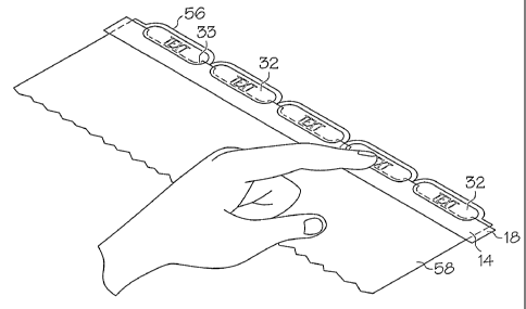
of a plurality of index dividers 58 as shown in FIGs. 7 and 8.
[0044] Holding the carrier strip 18 with the labels 32 having their adhesive
sides
exposed, the user then aligns the labels 32 with the tabs 56 of the index
dividers 58.
Each of the properly positioned labels 32 is then pressed flat down to form a
strong
adhesive bond onto the respective tabs 56 as depicted in FIG. 7. The carrier
strip 18
to which the labels 32 are less strongly adhesively attached is then pulled
away from
the adhered labels 32, leaving just the labels 32 on the tabs 56 as
illustrated in FIG. 8.
In that the carrier strip 18 has been removed from the liner 16 having the
labels
adhesively attached thereto, the liner 16 remains the original size and is
described as
multipassable. To prepare more labels 32 for new tabs if additional labels
were not
previously printed, the user simply reruns the multipassable label sheet
assembly 10
through the printer, printing on the subsequent array of labels to produce
aligned,
printed tab labels. It should be understood that the user can print as many
labels as
needed during a single printing process. Referring back to FIG. 6, after
printing, a
next carrier strip 53 may be removed from the liner sheet 16 to expose the
backsides
of the second line of printed labels 32. The second line of printed labels 32
is then
manipulated into position on a second set of staggered dividers (not shown),
the labels
32 pressed into position and the carrier strip removed. This can be understood
by
again viewing FIGS. 6 through 8.
[0045] As best illustrated in FIG. 8, during adherence of the labels 32 to the
tabs 56,
for a brief moment a portion of the carrier strip 18 is positioned between the
divider
12
CA 02651211 2008-11-04
WO 2007/130128 PCT/US2006/042604
tab 56 and the label 32. The user after pressing the label 32 against the
divider tab 56
adheres a major portion of the label 32 to the divider tab 56 and the small
overlap area
38 is attached to the carrier strip 18. The carrier strip 18 is then pulled
past the labels
32 so that the label edges 33 bend or flex slightly to allow the carrier strip
18 to be
removed. The label 32 exhibits sufficient tension and memory in its material
to cause
the edges 33 that are lifted up during removal of the carrier strip 18 to snap
back onto
the divider tab 56. The user may then smooth the edges to ensure complete
adhesion.
[0046] Referring now to FIG. 9, illustrated is an embodiment of a sheet
assembly 50
formed in generally the same manner as the sheet assembly 10 described in
FIGs. 1-3.
In this particular embodiment, a single label 52 is formed on a carrier strip
54 to allow
for removal and positioning of a single label 52. Each label 52 may be printed
and
peeled away from a liner for individual placement. It should be understood
that the
label 52 size and placement can vary depending upon the specific application
for the
label 52.
[0047] Referring now to FIGs. 10-12, illustrated is another embodiment of a
label
sheet assembly 60 including a plurality of labels 65. FIG. 10 is a cross-
section view
taken through line 10-10 of FIG. 11. Similar to the embodiment illustrated in
FIGs. 1-
3, the label sheet assembly 60 is formed of multiple layers 62 that include a
label
facestock 64 adhered with an adhesive 67 to a carrier sheet 68. The carrier
sheet may
optionally include a silicone release layer (not shown), such as that
described in FIG.
1 when adhesive 67 is not formed from an easily removable adhesive. The
carrier
sheet 68 is adhered with a heat activated coating 70 to a sheet 72, either a
paper or a
film. The heat activated coating 70 may be formed of a material such as
polyolefin in
a homogenous mixture or as a single component composition. In addition, heat
activated coating 70 may be formed of a copolyester, ethylene vinyl acetate,
ethylene
vinyl alcohol, polyvinyl chloride, ionomer resins, ethylene methyl acrylate,
ethylene
ethyl acrylate, ethylene acrylic acid, or the like. Heat activated coating 70
and sheet
72 together form a liner sheet 73. Alternatively, the heat activated coating
may be
replaced with a removable adhesive, ultraremovable adhesive or pattern-coated
adhesive, and thereby also not require a silicone release layer. Similar to
the first
embodiment, it should be understood that label facestock 64 includes a
printable
13
CA 02651211 2008-11-04
WO 2007/130128 PCT/US2006/042604
surface 76. The printable surface 76 may include surface treatments or
coatings to
enhance acceptance of indicia.
[0048] Referring more specifically to FIGs. 10 and 11, the label facestock 64
includes a plurality of cuts lines 74 that extend through the label facestock
64 and
define the perimeter of one or more labels 65 or portions of labels. In this
particular
embodiment and similar to the first embodiment, different numbers of columns
and
rows or different patterns (non-matrix) of the labels or carrier strip may be
formed as
needed. In addition, the carrier sheet 68 includes a plurality of cuts lines
78 that
extend through the carrier sheet 68 and define a plurality of cut edges 77 of
at least
one carrier strip 71 (FIG. 11). More specifically, as illustrated in FIG. 11,
cut lines 74
that define the label 65 having an uppermost edge 66 that is straight across
and inline
with the cut lines 78 in the carrier sheet (FIG. 10), defining a top edge 75
of the
carrier strip. The cuts lines 78 in the carrier sheet 68 (FIG. 10) further
define a
plurality of cut edges 77 in the carrier strip 71, wherein a small portion of
the
resulting carrier strip 71 covers a portion of each label 65 and a portion
between the
labels. This differential yields an overlap region that surrounds the
perimeter of the
label 65 and functions similar to the overlap region in the first embodiment,
namely to
lift up the array of labels 65 when the user separates the carrier strip 71
from the liner
sheet 73.
[0049] Referring now to FIG. 12, illustrated is an alternate embodiment in
which
cut lines 74 define the label 65 in a central portion of the carrier strip.
Similar to the
.embodiment illustrated in FIG. 11, the cuts lines 78 in the carrier sheet 68
further
define a plurality of cut edges 77 in the carrier strip 71, wherein a small
portion of the
resulting carrier strip 71 covers a portion of each label 65 and a portion
between the
labels. This differential yields an overlap region that surrounds the
perimeter of the
label 65 and functions similar to the overlap region in the first embodiment,
namely to
lift up the array of labels 65 when the user separates the carrier strip 71
from the liner
sheet 73. In the embodiments illustrated in FIGs. 11 and 12, sheet assembly 60
includes the liner sheet 73, including heat activated coating 70 and sheet 72,
the
carrier sheet 68, and the label facestock sheet 64 to form a laminate
construction that
is adapted to pass through a printer or copier multiple times in that the
liner sheet is
14
CA 02651211 2008-11-04
WO 2007/130128 PCT/US2006/042604
not cut and remains the same size. Desired indicia are printed on the labels
65 before
the carrier strip 71 is removed to a separated position.
[0050] During application of the labels 65 illustrated in FIGs. 11 and 12 to a
plurality of tabs on index dividers, folders, or the like, the carrier strip
71 is detached
from the liner sheet 73 in a manner similar to that previously described with
regard to
the first embodiment. A portion 80 of the carrier strip 71 that covers the
adhesive
layer 67 where the plurality of labels 65 have been defined is left behind
because it is
attached to the heat activated coating 70. This defines a window area (not
shown) in
the carrier strip 71 and allows the adhesive on labels 65 to be exposed and,
ready for
application onto the aligned tabs. The user then proceeds like described with
regard
to FIGs. 6-8 to use the carrier strip 71 to align the array of labels 65 with
the tabs of
the dividers, file folders, or the like. After proper alignment, the user then
applies the
array of labels 65 and removes the carrier strip 71, leaving the labels 65 on
the tabs.
To prepare more labels 65 for new tabs, the user simply reruns the
multipassable label
sheet assembly 60 through the printer, printing on the subsequent array of
labels to
produce aligned, printed tab labels. It should be understood that the user can
print as
many labels as needed during a single printing process.
[0051] Referring now to FIGs. 13 - 15, illustrated are a cross-section view
taken
through line 13-13 of FIG. 14, a front view of the label sheet assembly, and a
front
view of a portion of the carrier sheet. The label sheet assembly 90 is formed
of
multiple layers 92 that include a label facestock 94 adhered with an adhesive
96 to a
carrier sheet 98. It should be understood that carrier sheet 98 may optionally
include a
silicone release layer 99 as described in the previous embodiments. The
carrier sheet
98 when cut serves a similar function as both the carrier strip and liner in
the previous
embodiments. Similar to the first and second embodiments, label facestock 94
includes a printable surface 95.
[0052] The label facestock 94 includes a plurality of cuts 100 that extend
through
the label facestock 94 and define a perimeter of one of more labels 102 or
portions of
labels. In this particular embodiment and similar to the first embodiment,
different
numbers of columns and rows or different patterns (non-matrix) of the labels
can be
formed as needed. The carrier sheet 98 includes a plurality of cuts 104 that
extend
through the carrier sheet 98. As in previous embodiments, cuts 104 are
positioned
CA 02651211 2008-11-04
WO 2007/130128 PCT/US2006/042604
slightly inward of cuts 100 about at least a portion of the label 102, so that
the carrier
sheet 98 overlaps the labels 102 about at least a portion of the perimeter,
thereby
defining an overlap.
[0053] During application of the labels 102 to a plurality of tabs on index
dividers,
folder, or the like, a plurality of portions 105 is removed from the sheet
assembly 90,
exposing the adhesive backing on labels 102. The portions of 105 may be
removed
individually, or may be removed in a strip, as best illustrated in FIG. 15.
Portions of
105 have been cut to allow for a portion 106 of the carrier sheet 98 to remain
and tie
together the plurality of portions 105 upon removal to expose the adhesive
backing on
labels 102. The user then proceeds to maneuver the label sheet assembly 90 in
order
to align the array of labels 102 with a plurality of tabs of dividers, file
folders, or the
like. After proper alignment, the user applies pressure to the array of labels
102 and
removes the label sheet assembly 90, leaving the labels 102 on the tabs. In
this
particular embodiment sheet assembly 90 includes the carrier sheet 98 and the
label
facestock sheet 94 to form a laminate construction that is adapted to pass
through a
printer or copier. In that the carrier sheet 98 is cut into portions 105 that
are removed,
the sheet assembly 90 is sufficiently structurally weakened with exposed
adhesive and
is only passable through a printer or copier a single time. An alternate
embodiment
may include a gutter, similar to a previous embodiment, in which each separate
half of
the sheet assembly may be passed through a printer of copier a single time.
Desired
indicia are printed on the labels 102 before the portions 105 are removed to a
separated position.
[0054] Referring now to FIGs. 16-19, to minimize movement or shifting of a set
of
index dividers, file folders, or the like during the label application
process, methods
for temporarily aligning the set of index dividers are presented. As
illustrated in FIGs.
16-18, provided is a set of index dividers 110, including a plurality of tabs
112 having
a generally centralized portion 114 for placement of a label according to the
present
invention including identifying indicia. To provide proper alignment of the
labels on
tabs 112, the dividers 110 can be held in place by a single length or
plurality of
lengths, of removable tape 116 positioned across a lower portion 118 of the
tabs 112
outside of the portion 114 where the labels will be adhered as illustrated in
FIG. 16.
In the alternative, a single length of a tape 116 or a plurality of lengths of
tape 116
16
CA 02651211 2011-11-24
WO 2007/130128 PCT/US2006/04204
may be positioned across an edge 115, or multiple edges, of the set of index
dividers
110 as best illustrated in FIG. 17 or across a binding edge 117 of the
dividers 110 as
best illustrated in FIG. 18. The tape 116 can be in the form of either a
complete strip
or a plurality of sections that are spaced apart, covering the entire length
or width of
the divider set 110 as illustrated. After the labels have been applied, onto
the tabs 112,
the tape 116 is removed using an optional pull tab 119 as illustrated in FIG.
18 or by
simply lifting and removing the tape 16 from the dividers 110. Alternatively,
a glue or
adhesive that does not leave undesired residue on the edges of the dividers
110 can be
used in place of the tape 116.
[00551 Another method for aligning and securing sets of dividers during
application of the labels according to the present invention uses an alignment
guide as
illustrated in FIG. 19. More specifically, provided is an alignment guide 120
comprising at least one post 122 positioned on an alignment strip 124 in a
manner that
would align with the rings in a typical binder in which a set of dividers 128
may be
placed. In one embodiment, a series of at least two holes 126 are formed in
the
dividers 128 having a plurality of staggered tabs 130 to which a label is to
be adhered.
The at least one post 122 is smaller in dimensions than the holes 126= on the
dividers
128, thereby allowing the at least one post 122 to fit through the holes 126.
To
position the dividers 128 for label application, a user places the dividers
128 onto the
alignment guide 110, and more particularly places the at least one post 122
through
the divider holes 126, making sure to align all the dividers holes 126 with at
least one
post 122. This ensures that the tabs 130 for each divider 128 will be aligned
with the
tab 130 on adjacent dividers 128 and that the set of dividers 128 will not
shift during
the label application process. The at least one post 122 can be manufactured
using
thermoforming, injection molding, profile extrusion, or other methods known to
the
industries. In addition, an optional flap 136 may be incorporated with the
alignment
strip 124 to allow for folding over, as illustrated at 134, at least one of
the edges 132
of the set of dividers 128. It can be appreciated that posts, flaps or
combinations of
posts and flaps can be used as an alignment means. Alternative means for
aligning
the set of index dividers 128 of the present invention are also anticipated
herein, for
example, a pouch such as that taught in U.S. Patent No. 6,803,084.
17
CA 02651211 2008-11-04
WO 2007/130128 PCT/US2006/042604
[00561 Utilizing the above methods of label sheet assembly, application and
use of
an alignment guide, it is possible to form any number of sheet configurations
to
include labels for staggered tabs on a set of index dividers, folders, or the
like. In
addition, this technology is not limited to desktop printable sheets or to
sheets at all,
as it could be utilized to produce fan folded or roll products with unique
characteristics as well. Furthermore, the invention is not limited to index
tab labels,
but may include amongst other things address labels, or labels having a shape
other
than the illustrated rectangular shape. In addition, it should be appreciated
that
although all the cut lines in the various sheet assemblies are shown as being
formed
orthogonal to the edges of the sheet assembly, the cuts may be formed in a
manner
that is not orthogonal to the edges of the sheet assembly.
[00571 While at least one exemplary embodiment has been presented in the
foregoing detailed description, it should be appreciated that a vast number of
variations exist. It should also be appreciated that the exemplary embodiment
or
exemplary embodiments are only examples, and are not intended to limit the
scope,
applicability, or configuration of the invention in any way. Rather, the
foregoing
detailed description will provide those skilled in the art with a convenient
road map
for implementing the exemplary embodiment or exemplary embodiments. It should
be understood that various changes can be made in the function and arrangement
of
elements without departing from the scope of the invention as set forth in the
appended claims and the legal equivalents thereof.
18