Note: Descriptions are shown in the official language in which they were submitted.
CA 02651222 2011-03-28
1
METHOD AND APPARATUS FOR RAISING A SNOWPLOW
1. Background of the Invention
A. Field of Invention
[0001] This invention pertains to the art of methods and apparatuses for
snowplows and
more specifically to methods and apparatuses for raising a snowplow such that
when it is in the
raised position it is angled out of the way of the vehicle's headlights. This
invention makes
separate snowplow lights unnecessary.
B. Description of the Related Art
[0002] It is well known to provide snowplow assemblies for use in moving snow
and ice
from roads, driveways, parking lots and other such surfaces. Typically, the
snowplow assembly
is attached to a vehicle such as a pickup truck. Usually, the snowplow can be
moved by the
driver/operator of the vehicle by manipulating a control system within the
occupant compartment
of the vehicle. While numerous snowplow movements may be possible depending on
the
particular design of the snowplow assembly and the related controls, snowplow
movement
nearly always includes an adjustment between a lowered "use" position, where
the snowplow can
be used to plow snow from a ground surface, and a raised "transport" position,
where the
snowplow can be transported (without contacting any ground surface) by the
vehicle until use of
the snowplow is again required.
[0003] Generally, snowplow assemblies include: (1) a support frame that can be
connected to the vehicle; (2) a snowplow frame that supports a snowplow and
that is pivotally
connected to the support frame; and, (3) an adjustment mechanism, usually
including a hydraulic
system, for use in adjusting the position of the snowplow frame member. To
adjust the
CA 02651222 2008-08-01
WO 2007/092790 PCT/US2007/061569
2
snowplow from the use position to the transport position, the snowplow frame
(and thus the
snowplow) is raised causing it to pivot about the support frame.
[0004] While such known snowplow assemblies generally work well for their
intended
purpose, they have disadvantages. One disadvantage is that while the snowplow
is in the raised
transport position, it interferes with the light beams coming from the
vehicle's head lights. To
solve this problem, it is well known to provide an auxiliary lighting system
as part of the
snowplow assembly. While this option solves the lighting problem, it is costly
and cumbersome
to install.
[0005] The present invention includes embodiments that solve the snowplow
related
lighting problem, as well as other problems, in a new way that eliminates the
need for an
auxiliary lighting system.
II. Summary of the invention
[0006] According to one embodiment of this invention, a method of adjusting a
snowplow comprises the steps of:
(a) providing a snowplow assembly comprising: (1) a support frame for use in
connecting
the snowplow assembly to an associated vehicle; (2) at least one lift frame
member having a top
portion and a bottom portion operatively connected to the support frame; (3)
at least one
snowplow frame member that engages the lift frame member; (4) a snowplow
operatively
connected to the snowplow frame member and having a snowplow operation axis;
and, (5) an
adjustment mechanism for use in adjusting the position of the snowplow frame
member on the
lift frame member;
(b) lowering the snowplow frame member to the bottom portion of the lift frame
member
where the snowplow is positioned to plow snow and the snowplow operation axis
is substantially
parallel to a ground surface;
(c) raising the snowplow frame member to the top portion of the lift frame
member; and,
CA 02651222 2008-08-01
WO 2007/092790 PCT/US2007/061569
3
(d) pivoting the snowplow frame member on the top portion of the lift frame
member
where the snowplow operation axis is at an angle Al that is between 10 and 90
with respect to
the ground surface.
[0007] According to another embodiment of this invention, a snowplow assembly
comprises:
a support frame for use in connecting the snowplow assembly to an associated
vehicle;
a first lift frame member having a top portion and a bottom portion
operatively connected
to the support frame;
a first snowplow frame member that engages the first lift frame member;
a snowplow operatively connected to the first snowplow frame member and having
a
snowplow operation axis; and,
an adjustment mechanism for use in adjusting the position of the first
snowplow frame
member on the first lift frame member into at least two positions:
(1) a first position where the first snowplow frame member is on the bottom
portion of the first lift frame member, the snowplow is positioned to plow
snow, and the
snowplow operation axis is substantially parallel to a ground surface; and,
(2) a second position where the first snowplow frame member is on the top
portion of the first lift frame member and the snowplow operation axis is at
an angle Al that is
between 10 and 90 with respect to the ground surface.
[0008] One advantage of this invention is that the need for auxiliary snowplow
lights is
eliminated.
[0009] Another advantage of this invention is that snowplow assembly costs can
be
significantly reduced without any loss in quality.
[0010] Still another advantage of this invention is that the snowplow assembly
has a
reduced weight.
CA 02651222 2008-08-01
WO 2007/092790 PCT/US2007/061569
4
III. Brief Description of the Drawings
[0011] The invention may take physical form in certain parts and arrangement
of parts,
embodiments of which will be described in detail in this specification and
illustrated in the
accompanying drawings which form a part hereof and wherein:
[0012] FIGURE 1 is a side view of a vehicle equipped with a snowplow assembly
according to this invention with the snowplow shown in the lowered,
conventional plow
position.
[0013] FIGURE 2 is a side view similar to that shown in FIGURE 1 but showing
the
snowplow in the partially raised position.
[0014] FIGURE 3 is a side view similar to that shown in FIGURE 1 but showing
the
snowplow in the raised and flipped position where the snowplow does not
interfere with the
headlight beams.
[0015] FIGURE 4 is a side perspective view of the snowplow assembly of this
invention
shown separate from the vehicle.
[0016] FIGURE 5 is a side perspective view of the snowplow assembly shown in
FIGURE 4 showing the snowplow in the lowered position.
[0017] FIGURE 6 is a close-up side perspective view of the snowplow assembly
shown
in FIGURE 4 showing the snowplow in the raised but not flipped position.
[0018] FIGURE 7 is a close-up side perspective view of the snowplow assembly
shown
in FIGURE 4 showing the snowplow in the raised and flipped position.
CA 02651222 2008-08-01
WO 2007/092790 PCT/US2007/061569
[0019] FIGURE 8 is a top perspective view of a portion of the snowplow
assembly
shown in FIGURE 4.
5 [0020] FIGURE 9 is a side perspective view of a portion of the snowplow
assembly
shown in FIGURE 4.
[0021] FIGURE 10 is a close-up top view of a portion of the snowplow assembly
shown in FIGURE 4.
[0022] FIGURE 11 is a top view of a torsion spring providing tripping action
for the
snowplow assembly shown in FIGURE 4.
[0023] FIGURE 12 is a side view of the torsion spring shown in FIGURE 11.
[0024] FIGURE 13 is an end perspective view of the torsion spring shown in
FIGURE
11.
[0025] FIGURE 14 is a side perspective view of a mechanism that may be used to
attach the snowplow to the snowplow frame.
[0026] FIGURE 15 is an end perspective view of the mechanism shown in FIGURE
14.
[0027] FIGURE 16 is a close-up top perspective view of the mechanism shown in
FIGURE 14.
[0028] FIGURE 17 is a close-up top perspective view of the mechanism shown in
FIGURE 14.
CA 02651222 2008-08-01
WO 2007/092790 PCT/US2007/061569
6
[0029] FIGURE 18 is side perspective view showing another embodiment.
IV. Detailed Description of the invention
[0030] Referring now to the drawings wherein the showings are for purposes of
illustrating various embodiments of the invention only and not for purposes of
limiting the same,
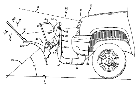
FIGURES 1-3 shows a snowplow assembly 50 including a snowplow 100 according to
one
embodiment of this invention. The snowplow assembly 50 may be attached to the
front of a
vehicle 10 which may be any type or size of vehicle that is adequately
designed to carry the
snowplow assembly 50. However, it should be noted that the snowplow assembly
50 of this
invention is lighter than conventional snowplow assemblies and thus it can be
mounted to and
used also with vehicles not typically considered "snowplow ready," such as a
Sport Utility
Vehicle (SUV). The vehicle 10 includes conventional headlights (only one
headlight 12 shown),
each of which creates a headlight beam 14. The purpose for and use of
headlights 12 are well
known and thus will not be described in detail here.
[0031] With continuing reference to FIGURES 1-3, the snowplow assembly 50 may
include a support frame 52 that supports the snowplow 100 throughout its
motion and when
being transported. A vehicle mount structure 54 is not required for this
invention but may be
secured to the vehicle 10 in a known manner. In this case, the support frame
52, and thus the
snowplow assembly 50, can be selectively attached to and detached from the
vehicle mount
structure 54 in any manner chosen with sound engineering judgment.
[0032] With reference now to FIGURES 1-10, the snowplow assembly 50 may also
have at least one lift frame member 56, two shown 56a, 56b, used to adjust the
height of the
snowplow 100 as will be discussed further below. Each lift frame member 56 has
a top portion
58 and a bottom portion 60. The bottom portion 60 may be operatively connected
to the support
frame 52 such as by welding, bolting or other known methods. In another
embodiment, the lift
CA 02651222 2008-08-01
WO 2007/092790 PCT/US2007/061569
7
frame member 56 may be made together with the support frame 52 as a single
component. Each
lift frame member 56 may have at least one track 62, two shown 62a, 62b, to
receive a later to be
described track engaging device 200. In one embodiment, the tracks 62a, 62b
are formed on
opposite outer side surfaces of the lift frame member 56. Each track 62 may be
substantially S-
shaped with a linear mid-portion 64 and oppositely curved upper and lower
portions 66, 68. In
one embodiment, the linear mid-portion 64 is substantially perpendicular to a
ground surface 16.
The upper portion 66 may be curved toward the snowplow 100 and the lower
portion 68 may be
curved away from the snowplow 100 for purposes to be described further below.
Each track 62
may have a stop location 70 that is used to stop the motion of the track
engaging device 200
upward along the track 62. 70a references the stop location for track 62a and
70b references the
stop location for track 62b. In one embodiment, each stop location 70 includes
a curved surface,
as shown, but other methods of stopping the motion of the track engaging
device 200 can also be
used. At least a portion of the curved upper portion 66 may be used, in one
embodiment, as the
stop location 70. At least one of the tracks 62 may have a second stop
location 72 that is used to
stop the motion of the track engaging device 200 downward along the track 62,
as will described
further below. The second stop location 72 may also, in one embodiment,
include a curved
surface, as shown. In a more specific embodiment, the second stop location 72
may comprise a
groove 74 formed in the surface of the track 62. Each lift frame member 56 may
also have a
contact surface 76 to be used as described further below. Where two lift frame
members 56a,
56b are used, they may be positioned on opposite sides of the support frame
52. A support
member 78 may be connected between the lift frame members 56a, 56b to add
structurally
stability to the unit. The support member 78 may also be used, in one
embodiment, to assist with
the lifting of the snowplow 100 as will be discussed below.
[0033] With continuing reference to FIGURES 1-10, the snowplow assembly 50 may
also have a snowplow frame 80 used to support the snowplow 100 to the lift
frame 56. The
connection of the snowplow 100 to the snowplow frame member 80 can be any
connection
chosen with sound engineering judgment. The snowplow 100 may, for example, be
movable
about a vertical snowplow axis VA and/or movable about a horizontal axis HA
(sometimes
CA 02651222 2008-08-01
WO 2007/092790 PCT/US2007/061569
8
referred to as "tripping") as is well known by those of skill in the art. One
embodiment of a
torsion spring 11 that may be used with this invention is shown in FIGURES 11-
13. The
snowplow 100 has a snowplow operation axis OA that is substantially parallel
to the ground
surface 16 when the snowplow 100 is being used to plow snow on the ground
surface 16,
assuming the plow is not tripping about the horizontal axis HA. The snowplow
frame 80 may
have at least one contact surface 81 that is used to contact the contact
surface 76 of the lift frame
member 56 as will be described further below. In one embodiment the contact
surface 81
extends inwardly from one, or both snowplow frame 80a, 80b. In another
embodiment, the
contact surface 81 is an outer surface of a support member 83 that extends
between the
snowplow frame 80a, 80b.
[0034] Still referring to FIGURES 1-10, the snowplow frame 80 may also include
the
previously noted track engaging device 200 to engage the track 62 (or tracks)
of the lift frame 56.
In one embodiment, shown, the snowplow frame 80 includes a snowplow frame
member 80a
that operatively engages the lift frame member 56a and a snowplow frame member
80b that
operatively engages the lift frame member 56b. The snowplow frame members 80a,
80b may be
moved along the tracks 62 of the lift frame members 56a, 56b using the track
engaging device
200. More specifically, each snowplow frame member 80a, 80b may include a pair
of
connection devices 82a, 82b having track engaging surfaces that engage the
tracks 62a, 62b.
While the connection devices 82a, 82b can be of any design chosen with sound
engineering
judgment, for the embodiment shown, they comprise rollers 84a, 84b having
surfaces that roll
along the tracks 62a, 62b, respectively, as the snowplow frame 80 is moved
relative to the lift
frame 56.
[0035] With continuing reference to FIGURES 1-10, the snowplow assembly 50 may
also have an adjustment mechanism 90 used to adjust the position of the
snowplow frame 80,
and thus the snowplow 100, on the lift frame 56. The adjustment mechanism 90
may include a
lift cylinder 92 attached between the support frame 52 and the snowplow frame
80. The lift
cylinder 92 may be a hydraulic cylinder and may be operated by a conventional
hydraulic system
CA 02651222 2008-08-01
WO 2007/092790 PCT/US2007/061569
9
(not shown). The particular connection between the lift cylinder 92 and the
snowplow frame
member 80 can be any chosen with sound engineering judgment. For the
embodiment shown, a
first link 30 is pivotally attached at one end to the snowplow frame 80 and
pivotally attached at
the opposite end to a second link 51. The second link 51 has one end pivotally
attached to the
first link 30 and the opposite end pivotally attached to the distal end of the
rod 96 which extends
from the lift cylinder 92.
[0036] With continuing reference to FIGURES 1-10, the adjustment mechanism 90
may be used to adjust the snowplow frame 80 and snowplow 100 into at least two
positions. The
first position, shown in FIGURE 1, is where the snowplow frame members 80a,
80b, are located
on the bottom portions 60, 60 of the lift frame members 56a, 56b, the snowplow
100 is
positioned to plow snow, and the snowplow operation axis OA is substantially
parallel to the
ground surface 16. By "positioned to plow snow" it is meant that the snowplow
100 is
positioned to be used to plow snow from the ground surface 16 without need for
any further
adjustment relative to the lift frame 56. The second position, shown in FIGURE
3, is where the
snowplow frame members 80a, 80b, are located on the top portions 58, 58 of the
lift frame
members 56a, 56b and the snowplow operation axis OA is at an angle Al that is
between 10
and 90 with respect to the ground surface 16. For the embodiment shown, the
angle Al is
between 30 and 50. The second position is ideal for transporting the
snowplow assembly 50 to
the next place of use. One benefit to adjusting the snowplow frame 80 and
snowplow 100 into
the second position is that in this position the snowplow 100 does not
interfere with the headlight
beams 14. As a result, there is no requirement for an auxiliary lighting
system as part of the
snowplow assembly 50, as is currently required. This reduces the cost of the
snowplow
assembly 50 and reduces the mass (weight) of the snowplow assembly 50 so that
the snowplow
assembly 50 can be used on vehicles not ordinarily thought of as being a good
choice for snow
plowing.
[0037] With continuing reference to FIGURES 1-10, the operation of the
snowplow
assembly 50 will now be described. To raise the snowplow frame 80 and the
snowplow 100
CA 02651222 2008-08-01
WO 2007/092790 PCT/US2007/061569
from the conventional plow position, shown in FIGURE 1, the operator activates
the lift cylinder
92 using a later to be described control system chosen with sounding
engineering judgment, to
lift the snowplow frame 80. The lift cylinder 92 causes the track engaging
surfaces of the
connection devices 82a, 82b to move upward along the tracks 62a, 62b. The
generally vertical
5 orientation of the mid-portions 64, 64 of the lift frame members 56a, 56b
permits efficient
raising of the snowplow 100. It should be noted that as the snowplow frame 80
and the
snowplow 100 continue to be raised along the mid-portions 64, 64 the snowplow
operation axis
OA remains substantially parallel to the ground surface 16. As a result, the
snowplow 100
reaches a position, shown in FIGURE 2, where the snowplow 100 interferes with
the headlight
10 beams 14. Continued raising of the snowplow 100 causes each connection
device 82a to move
into the curved upper portion 66 of the track 62a and into the stop location
70a. Still further
raising of the snowplow 100 causes the snowplow frame 80 to pivot in direction
Dl about each
connection device 82a (at this stage each connection device 82a ceases motion
along the track
62a while each connection device 82a is position in stop location 70a). While
the snowplow
frame 80 pivots in direction D1 about each connection device 82a, each
connection device 82b
continues to move generally upward along track 82b. This motion continues
until each
connection device 82b moves into stop location 70b. This is the position shown
in FIGURE 3.
Note that in this position, the snowplow 100 does not interfere with the
headlight beams 14. As
a result, this is an ideal on vehicle "storage" position for transporting the
vehicle 10 and the
snowplow assembly 50.
[0038] With continuing reference to FIGURES 1-10, for the embodiment shown,
the
location of the center of gravity, labeled CG, for the portion of the snowplow
assembly 50 that is
position adjusted, ensures that the snowplow frame 80 will tend toward
pivoting in direction Al
as the snowplow 100 is raised and lowered. This general location for the CG
helps maintain the
connection devices 82a, 82b against the tracks 62a, 62b as the snowplow 100 is
raised and
lowered. In order to prevent the snowplow frame 80 from pivoting toward the
vehicle 10, a stop
member 101, which in one embodiment is a bolt, is used. Should the snowplow
frame 80 pivot
CA 02651222 2008-08-01
WO 2007/092790 PCT/US2007/061569
11
to a certain extent, a portion of the snowplow assembly 50, in one embodiment
the first link 30,
will contact the stop member 101 and further pivoting motion is thus
prevented.
[0039] With continuing reference to FIGURES 1-10, to lower the snowplow frame
80
and the snowplow 100 from the storage position, shown in FIGURE 3, the
operator again
activates the lift cylinder 92. As the lift cylinder 92 operates the snowplow
frame 80 pivots in
direction D2, opposite to direction Dl, about each connection device 82a while
each connection
device 82b moves out of stop location 70b and then moves generally downward
along track 82b.
In one embodiment, the required operation of the lift cylinder 92 to cause the
snowplow frame
80 to pivot in direction D2 is simply a lowering of the rod 96. In another
embodiment, the
required operation of the lift cylinder 92 to cause the snowplow frame 80 to
pivot in direction D2
is a slight raising of the rod 96 that moves the connection device 82b out of
stop location 82b.
With this embodiment, as the snowplow frame 80 is being lifted, the contact
surface 81 of the
snowplow frame 80 may contact the contact surface 76 of the lift frame member
56. This
contact makes it easier for the connection device 82b to come out of stop
location 82b and move
downwardly along track 62b. The lift cylinder 92 is then lowered. In either
embodiment,
continued lowering of the snowplow 100 permits the connection devices 82a to
move downward
along the tracks 62 through the mid-portions 64, 64 of the lift frame members
56a, 56b and to
the lower portions 68, 68. As noted above, in one embodiment a track 62 may
have a second
stop location 72. For the embodiment shown in FIGURE 3, the stop location 72
receives the
connection device 82b. This permits the snowplow frame 80 to pivot about the
connection
device 82b in direction D2. This is useful when, for example, the ground
surface 16 being
plowed slopes downward from the front of the vehicle 10 and it is thus
beneficial to permit the
snowplow 100 to be angled below the position used when the ground surface 16
is relatively flat
or lever.
[0040] With reference now to FIGURES 1-3, the particular control system used
to
operate the snowplow assembly 50 can be any chosen with sound engineering
judgment. In one
embodiment the control system 220 includes a hydraulic system 222 and a
controller 230. The
CA 02651222 2008-08-01
WO 2007/092790 PCT/US2007/061569
12
hydraulic system 222 provides hydraulic fluid to operate the lift cylinder 92
and any other
hydraulically activated components as is well known in the art. The controller
230 is the device
that the operator uses to activate the hydraulic system 222 and thus the
related hydraulic
components and any other components as desired. The particular controller 230
can be of any
conventional type such as a controller fixed within the operator compartment
of the vehicle 10 or
a controller that is not attached and thus easy for the operator to move, as
desired. The controller
230 may be hard wired to the snowplow assembly 50 or may use radio frequency
(RF)
technology or other wireless technology. The controller 230 may include
various conventional
control buttons 232, including: (1) a control button which, when pressed,
causes the snowplow
100 to pivot in a Left direction about vertical snowplow axis VA (it may be
labeled "L", as
shown); (2) a control button which, when pressed, causes the snowplow 100 to
pivot in a Right
direction about vertical snowplow axis VA (it may be labeled "R", as shown);
(3) a control
button which, when pressed, causes the snowplow 100 to move Upward (it may be
labeled "U",
as shown); and, (4) a control button which, when pressed, causes the snowplow
100 to move
Downward (it may be labeled "D", as shown.)
[0041] With continuing reference to FIGURES 1-3, for the embodiment shown, the
controller 230 includes two additional control buttons used with this
invention. While the actual
labeling may be any as desired, one control button 232a may be labeled "Flip"
and the other
control button 232b "Unflip." The Flip button 232a is pressed by the operator
when it is desired
to adjust the snowplow 100 into the second position shown in FIGURE 3. In this
case, the
snowplow 100 is not only raised but the snowplow frame 80 is pivoted (flipped)
about
connection devices 82a in direction D1 as explained above. The Unflip button
232b is pressed
by the operator when it is desired to adjust the snowplow 100 out of the
second position shown
in FIGURE 3. In this case, the snowplow frame 80 is pivoted (unflipped) about
connection
devices 82a in direction D2 as explained above. Pressing one or both buttons
232a, 232b may
activate a timer along with the appropriate hydraulics to perform the required
function. Pressing
the Unflip button 232b, for example, may cause the snowplow frame 80 to raise
for three (3)
CA 02651222 2008-08-01
WO 2007/092790 PCT/US2007/061569
13
seconds (or some other predetermined time) to permit the snowplow frame 80 to
pivot as
described above.
[0042] With reference now to FIGURES 14-17, the snowplow assembly 50 may
include other components and operations not yet described. A pin pull
mechanism 300 may be
used to attach the snowplow 100 to the snowplow frame 80. Handle 302 is used
to pull bar 304
which is connected to pins 306 and 308. A spring 310 may be used to keep the
pins 306, 308
biased toward the attached position. To detach the snowplow 100, the handle
302 is pulled
against the spring 310 force. This causes pull bar 304 to move and the pins
306, 308 are released
enough to detach the snowplow 100. More specifically, when the pull bar 304 is
moved, a
surface 350 goes beyond surface 360. At this point, the pins 306, 308 can be
rotated clockwise
(as shown) 10 or 20 degrees or so to lock onto surface 360. To put the pin
back in, you rotate it
back counterclockwise and it will snap back in.
[0043] With reference now to FIGURE 18, in yet another embodiment, each lift
frame
member 56a, 56b may have a partially enclosed track 62, as shown. Each lift
frame member
56a, 56b may have a track 26 on one side thereof. The snowplow frame 80 is
connected to the
track 26 so that the snowplow frame 80, and thus the snowplow 100, can be
moved along the
track 26. The snowplow frame member 80 may have a pair of connection points
336, 336 that
are received within the track 26. The connection points 336, 336 can be of any
design chosen
with sound engineering judgment such as rollers, as shown. The connection
points 336, 336 can
be moved along the track 26 similar to the manner described above.
[0044] Various embodiments have been described, hereinabove. It will be
apparent to
those skilled in the art that the above methods and apparatuses may
incorporate changes and
modifications without departing from the general scope of this invention. It
is intended to
include all such modifications and alterations in so far as they come within
the scope of the
appended claims or the equivalents thereof.
CA 02651222 2008-08-01
WO 2007/092790 PCT/US2007/061569
14
Having thus described the invention, it is now claimed: