Note: Descriptions are shown in the official language in which they were submitted.
CA 02651744 2008-11-07
DEVICE FOR PRODUCING A METAL STRIP BY
CONTINUOUS CASTING
The invention concerns a device for producing a metal
strip by continuous casting with a casting machine in which a
slab is cast, preferably a thin slab, where at least one
milling machine is installed downstream of the casting machine
in the direction of conveyance of the slab, at least one
surface of which and preferably two opposite surfaces of which
can be milled down in the one or more milling machines, and
where at least one descaling system is installed downstream of
the casting machine in the direction of conveyance of the
slab.
In the continuous casting of slabs in a continuous
casting installation, surface defects can develop, for
example, oscillation marks, casting flux defects, or
longitudinal and transverse surface cracks. These occur in
both conventional and thin-slab casting machines. Therefore,
the conventional slabs are subjected to flame descaling in
some cases, depending on the intended use of the finished
strip. Many slabs are subjected to flame descaling as a
1
CA 02651744 2008-11-07
general rule at the customer's request. In this connection,
the requirements on surface quality have been continuously
increasing in thin-slab installations.
Flame descaling, grinding, and milling are available
methods of surface treatment.
Flame descaling has the disadvantage that the material
that has been flashed off cannot be melted down again without
processing due to the high oxygen content. In the case of
grinding, slivers of metal become mixed with the grinding
wheel dust, so that the abraded material must be disposed of.
Both methods are difficult to adapt to the given conveyance
speed.
Therefore, surface treatment by milling must be considered.
The hot millings are collected during the milling operation.
They can then be briquetted and melted down again without
processing and without any problems and thus returned to the
production process. Furthermore, the miller speed can be
easily adjusted to the conveyance speed (casting speed,
feeding speed into the finishing train). The device of the
aforesaid type that constitutes the object of the invention
thus involves the use of milling.
A device for producing a metal strip by continuous
casting, in which a milling machine is used for milling down
2
CA 02651744 2008-11-07
the surface of a slab, is already known, for example, from CH
584 085 and DE 199 50 886 Al.
A similar device is also disclosed by DE 71 11 221 Ul.
This document discloses the processing of aluminum strip with
utilization of the casting heat, in which the machine is
connected with the casting installation.
In-line removal of material from the surface of a thin
slab (flame descaling, milling, etc.) shortly before a rolling
train on the upper side and underside or on only one side has
also already been proposed. EP 1 093 866 A2 is cited in this
connection.
DE 197 17 200 Al discloses another embodiment of a
surface milling machine. This document describes, among other
things, the adjustability of the milling contour of the
milling device, which is installed downstream of the
continuous casting installation or upstream of a rolling
train.
Another embodiment and arrangement of an in-line milling
machine in a conventional hot strip mill for treating a near-
net strip are proposed by EP 0 790 093 B1, EP 1 213 076 B1,
and EP 1 213 077 B1.
In the surface treatment of thin slabs in a so-called CSP
plant, about 0.1-2.5 mm should be removed from the surface on
3
CA 02651744 2008-11-07
one or both sides of the hot slab in the processing line ("in
line"), depending on the surface defects that are detected. A
thin slab that is as thick as possible is advisable (H = 60-
120 mm) so as not to diminish the output too much.
The in-line milling machine is not generally used for all
products of a rolling program but rather only for those that
have relatively high surface requirements. This is
advantageous from the standpoint of output, reduces milling
machine wear, and therefore is useful.
The in-line milling machine requires building space. The
slab temperature loss in the vicinity of the machine is an
interfering factor. This applies to installation after the
casting machine, since the casting speed (mass flow) is
usually low. However, even before the finishing train, the
temperature loss is disadvantageous, because, especially in
the case of relatively thin strip, a high final rolling
temperature, combined with an acceptable strip runout speed
from the finishing train, is actively sought.
Therefore, the objective of the present invention is to
improve a device for producing a metal strip by continuous
casting with the use of a milling machine in such a way that
optimum slab machining is possible, even with different
process-engineering requirements. In particular, temperature
4
CA 02651744 2008-11-07
losses during slab processing and machining are to be kept
small.
The solution to this problem in accordance with the
invention is characterized by the fact that the milling
machine and the descaling system are realized as an integral
unit.
In this regard, the milling machine and the descaling
system are preferably housed in a common housing.
The milling machine can comprise two milling cutters.
The descaling system preferably comprises high-pressure
nozzles for descaling fluid. However, it is also possible to
use other types of descaling elements which in themselves are
already known from the prior art (e.g., ultrasonic descaling
elements).
A modification of the invention provides that a plurality
of high-pressure nozzles is arranged in the milling and
descaling unit in the direction of conveyance.
In addition, it can be provided that a furnace is
installed upstream of the milling and descaling unit with
respect to the direction of conveyance. One milling cutter
each can be installed for machining the upper side and the
underside of the slab. The two milling cutters can be spaced
some distance apart in the direction of conveyance. In
CA 02651744 2008-11-07
addition, it can be provided that each milling cutter
cooperates with a support roll arranged on the other side of
the slab.
A rolling stand or a rolling train is usually installed
downstream of the milling and descaling unit with respect to
the direction of conveyance.
The device is preferably designed in such a way that two
different operating modes can be used. In accordance with a
first possibility, it is provided that the device is designed
in such a way that the descaling system and the milling
machine can be alternatively used at one's option. In a
second alternative, it is provided that the device is designed
in such a way that the descaling system and the milling
machine can be operated at the same time.
The descaling system and the milling machine can thus be
activated simultaneously. However, in order to produce a high
run-in temperature into the rolling train, it can generally be
advantageously provided, when the surface quality is good,
that either the milling machine or the descaling system is
used.
The proposed solution makes it possible to keep
temperature losses low during slab processing and machining.
This results in the qualitatively improved production of
6
CA 02651744 2008-11-07
slabs, especially thin slabs.
Furthermore, it is a considerable advantage that the slab
production can be carried out much more economically and
ecologically as far as the milling of the slab surface and the
descaling are concerned. Specifically, it becomes possible in
a very advantageous way to use the fluid (water) needed for
the descaling also to support the milling process, so that the
fluid requirement for this is significantly reduced.
A specific embodiment of the invention is illustrated in
the drawings.
-- Figure 1 is a schematic side view of a device for
producing a metal strip by continuous casting, in which a
milling machine and a descaling system are used.
-- Figure 2 is an enlarged section of Figure 1 showing
the milling and descaling unit.
Figure 1 shows a device for producing a metal strip 1 by
continuous casting. The metal strip 1 or the corresponding
slab 3 is continuously cast by well-known means in a casting
machine 2. The slab 3 is preferably a thin slab. Immediately
downstream of the casting machine 2, the slab 3 is cleaned in
a cleaning installation 15. A surface inspection is then
performed by means of a surface measuring device 16. The slab
3 then enters a furnace 11 for the purpose of holding it at a
7
CA 02651744 2008-11-07
desired process temperature. The furnace is followed by a
transverse conveyor 17.
Downstream of the furnace 11 and the transverse conveyor
17, the slab 3 enters an integrated unit 6 that consists of a
combined milling machine 4 and descaling system 5. The
milling machine 4 and the descaling system 5 have a common
housing 7 or at least are arranged very close together. In
the integrated unit 8, the slab 3 is subjected to a combined
milling and/or descaling process. Following this operation --
as viewed in the direction of conveyance F of the strip 1 or
slab 3 -- the metal strip 1 enters a single-stand or multiple-
stand rolling train. A rolling stand 13 and a rolling stand
14 are indicated in Figure 1.
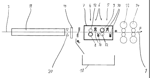
Details of the integrated unit 6, which consists of the
combined milling machine and descaling system, are shown in
Figure 2.
Two milling cutters 8 and 9 are installed in the housing
7 some distance apart in the direction of conveyance F. The
milling cutter 8 that is on the upstream side with respect to
the direction of conveyance F mills the underside of the slab
3 in a way that in itself is already well known. The milling
cutter 9 that is on the downstream side with respect to the
direction of conveyance F mills the upper side of the slab 3.
8
CA 02651744 2008-11-07
Both milling cutters 8, 9 cooperate with support rolls 12,
which are positioned on the respective opposite side of the
slab 3 from each milling cutter 8, 9.
As the drawing also shows, high-pressure nozzles 10 are
installed in the housing 7 in the form of nozzle spray bars,
which extend over the entire length of the slab 3 (i.e., in
the direction normal to the plane of the drawing in Figure 2).
The high-pressure nozzles 10 deliver water in a well-known way
to the surface of the strip to remove scale from the surface.
Naturally, it is also basically possible to use other types of
descaling elements.
It is advantageous that the water delivered by the
nozzles 10 can simultaneously be used to cool the milling
cutters 8, 9, so that the latter have a sufficiently long
service life.
A collecting tank 18 for milled material or for scale is
arranged below the integral unit 6. Devices for removing
milled cuttings and/or scale can also be provided there.
A surface inspection 20 can be performed upstream of the
integral unit 6. In addition, in the illustrated specific
embodiment, a profile measurement 19 is provided.
The proposed integral unit 6 with a milling machine 4 and
a descaling system 5 can thus be optimally adapted to the
9
CA 02651744 2008-11-07
specific application and has the task of optimizing
temperature control at high temperature or with low
temperature loss.
The proposed idea is thus aimed at completely integrating
the milling machine in the vicinity of the descaling sprayer.
The two surface-controlling devices (descaling sprayer,
milling machine) can thus be selectively used in a flexible
way. The water from the descaling sprayer can simultaneously
be used to flush away the milled cuttings.
CA 02651744 2008-11-07
List of Reference Symbols
1 metal strip
2 casting machine
3 slab
4 milling machine
descaling system
6 integral unit
7 housing
8 milling cutter
9 milling cutter
high-pressure nozzle
11 furnace
12 support roll
13 rolling stand
14 rolling stand
cleaning installation
16 surface measuring device
17 transverse conveyor
18 collecting tank
19 profile measurement
surface inspection
F direction of conveyance
11