Note: Descriptions are shown in the official language in which they were submitted.
CA 02651872 2008-11-10
WO 2007/134191 PCT/US2007/068704
DESCRIPTION
DETECTING MULTIPLE TYPES OF LEUKOCYTES
[0001] This application claims priority to U.S. Provisional Patent application
serial number 60/799,562 filed May 10, 2006, entitled "Detecting Multiple
Types of
Leukocyte," which is incorporated herein by reference in its entirety.
FIELD OF THE INVENTION
[0002] The present invention relates to detecting multiple types of leukocytes
in a blood sample material, and differentiating between concentrations of
detected
leukocytes.
II. BACKGROUND
[0003] The development of smart sensors capable of discriminating different
analytes, toxins, and bacteria has become increasingly important for clinical,
environmental, health and safety, remote sensing, military, food/beverage,
and/or
chemical processing applications. Some sensors have been fashioned for single
analyte detection. Other sensors are capable of solution phase multi-analyte
detection. Latex agglutination tests ("LATs") are used to detect many
different types
of analytes in clinical analyses. LATs employ colloidal polymer microspheres
to
determine the presence (or absence) of analytes. Commercially available LATs
for
more than 60 analytes are used routinely for the detection of infectious
diseases,
illegal drugs, and pregnancies. LATs generally operate on the principle of
agglutination of latex particles (e.g., colloidal polymer microspheres). LATs
are set
up such that agglutination occurs when antibody-derivatized latex particles
become
effectively "cross-linked" by a foreign antigen, resulting in the attachment
of the
particle to, or the inability of the particle to pass through, a filter. The
cross-linked
latex particles are then detected colorimetrically upon removal of the antigen
carrying
solution.
[0004] More recently, "taste chip" sensors have been employed that are
capable of discriminating mixtures of analytes, toxins, and/or bacteria in
medical,
food/beverage, and environmental solutions. Certain sensors of this type are
-1-
CA 02651872 2008-11-10
WO 2007/134191 PCT/US2007/068704
described in U.S. Patent Application Publication No. 20020197622 to McDevitt
et al.,
which is incorporated by reference as if fully set forth herein.
[0005] White blood cell counts are a vital part of the complete blood count
(CBC), one of the most commonly administered health test world-wide. The test
offers to physicians a tremendous amount of information that is very often the
basis
for diagnosis or the administration of specific tests. While manual
differential cell
counts have been the reference for more than a century of laboratory
haematology,
advances in electronics, and development of fluorescence-based immunological
methods have led to powerful cell counting methods such as Flow Cytometry
(FC).
Currently, cell differentials are obtained from hematology analyzers, or flow
cytometers, both of which are typically large, expensive instruments that
require
trained technicians and maintenance. These features make the existing methods
scarce
in resource poor settings. In resource poor settings diagnosis rarely involves
these
tools. Even within developed countries, standardization of the data has been
reported
as difficult because of the diversity in the number of methods (single
platform vs. dual
platform), and high susceptibility to the instrumentation, users, and
inaccuracy,
especially in the case of haematology analyzers. As cell enumeration is a very
basic
and crucial support of diagnosis, prognosis, and treatment, an alternative
cell counting
method to traditional hematology analyzers or flow cytometers that would
potentially
be cheaper, portable, and accurate is warranted.
[0006] There are five types of white blood cells (lymphocytes, monocytes,
neutrophils, eosinophils, and basophils). A basic three part differential
targets the
identification and enumeration of three groups: lymphocytes, monocytes, and
granulocytes (composed of neutrophils, eosinophils, and basophils).
[0007] Enumeration of monocytes, granulocytes, and lymphocytes can have
major implications in the diagnosis and treatment of a large number of
diseases and
conditions. Examples include, but are not limited to, HIV-AIDS (total
lymphocytes
and subsets), Malaria (monocytes), cardiac disease (total WBC and monocytes),
and
lymphocytopenia. Leukocytosis, or elevated WBCs has numerous causes, including
of course an increase in the number of lymphocytes.
-2-
CA 02651872 2008-11-10
WO 2007/134191 PCT/US2007/068704
[0008] As WBCs help the body fight infections, an abnormal total white blood
cell (WBC) count can be associated with bacterial or viral infection,
inflammation, or
stress. The WBC differential count consists of the enumeration of three or all
five of
the WBC types, neutrophils, lymphocytes, monocytes, eosinophils, and
basophils.
Each subtype has a unique role in the immune system, and variations in these
subpopulations have significant diagnostic and prognostic values. Though WBC
differential counts are traditionally obtained with a hematology analyzer, the
use of
flow cytometry as a means to count WBC and WBC subtypes has substantially
increased in the past decades, as have the scope and number of FC-based
applications.
Despite notable efforts in the past few years, the size, cost, and
technological
complexity of such instrumentation have limited its use for point of care
(POC)
testing. We present here a simple methodology amenable to lab on a chip
approach
that can be used to obtain 3-, or even a 5-part differential that could be
administered at
the POC.
SUMMARY OF THE INVENTION
[0009] In various embodiments, systems, methods, and apparatuses to analyze
one or more biological samples containing one or more types of white blood
cells, and
in particular to determine a white blood cell differential count, are
provided. Samples
may be fluid samples. In some embodiments, an analyte-detection system is
capable
of analysis of a sample that includes individual analytes and mixtures of
analytes. In
some embodiments, the analytes include lymphocytes. The analyte-detection
system
may include a cartridge.
[0010] In some embodiments, the cartridge includes one or more collection
regions, one or more fluid delivery systems, one or more channels, one or more
reagent regions, one or more reservoirs, a detection region, or combinations
thereof.
The detection region may include one or more detection systems. In some
embodiments, one or more collection regions, one or more detection systems,
one or
more fluid delivery systems, one or more channels, one or more reagent
regions, and
one or more reservoirs are: coupled to; at least partially positioned on; or
at least
partially positioned in the cartridge. In some embodiments, one or more
collection
regions, one or more detection systems, one or more fluid delivery systems,
one or
more channels, one or more reagent regions, and one or more reservoirs are at
least
-3-
CA 02651872 2008-11-10
WO 2007/134191 PCT/US2007/068704
partially contained in a body of the cartridge. In some embodiments, a body of
the
cartridge includes a plurality of layers coupled together.
[0011] In some embodiments, the body of the cartridge includes openings.
The openings may be configured to receive one or more components used to
facilitate
analyte detection. One or more channels may couple the openings together. In
some
embodiments, one or more collections regions, one or more of the detection
systems,
one or more fluid packages, or combinations thereof are at least partially
placed in
one or more of the openings.
[0012] The collection region of a cartridge may receive a fluid and/or sample.
In some embodiments, a collection region may include a cover.
[0013] Detection systems may include membrane-based detection systems
and/or particle-based detection systems. The detection systems are configured
to
interact with at least a portion of a sample to allow detection of an analyte.
[0014] In some embodiments, a membrane of a membrane-based detection
system, when one or more samples are applied to the membrane, at least
partially
retains desired matter in or on the membrane. In some embodiments, one or more
viewing windows are optically coupled to the membrane, the viewing window
being
configured to allow one or more detectors to view at least a portion of the
membrane.
[0015] In some embodiments, an anti-reflective material is coupled to the
membrane. In some embodiments, the anti-reflective material is configured to
inhibit
reflection of light applied to the sample on the membrane, such that an image
of at
least a portion of the sample in or on the membrane is improved with respect
to an
image taken of the sample in the absence of the anti-reflective material.
[0016] One or more fluid delivery systems are configured to transport fluid
from a first location to a second location in or on the cartridge. In some
embodiments, a fluid delivery system includes one or more fluid packages
and/or one
or more syringes configured to facilitate transport of fluid. In some
embodiments, at
least one fluid delivery package is configured to create a partial vacuum,
when
opened, in one or more of the channels during use.
-4-
CA 02651872 2008-11-10
WO 2007/134191 PCT/US2007/068704
[0017] Fluid may be transported through one or more channels of the cartridge
from a first location to a second location in or on the cartridge. Channels
may couple
one or more collection regions, one or more detection regions, and one or more
fluid
delivery systems to each other. In some embodiments, one or more channels are
part
of a fluid delivery system. In some embodiments, a shape or elevation of at
least a
portion of one or more of the channels is configured such that fluids flowing
in or
through one or more channels during use are selectively directed through the
one or
more channels. In some embodiments, an inside material of or on at least a
portion of
one or more of the channels is configured to selectively direct fluids flowing
in or
through one or more of the channels during use.
[0018] Valves positioned in or on one or more of the channels and/or a
cartridge may control fluid flow. In some embodiments, one or more pinch
valves are
coupled to one or more of the channels and/or the cartridge. In some
embodiments,
applying pressure to one or more pinch valves positioned in or on the
cartridge
controls fluid flow through one or more of the channels.
[0019] One or more vents may be coupled to one or more of the channels. In
some embodiments, gas is released from the cartridge through vents as fluids
flow
through one or more of the channels.
[0020] One or more reagent regions may include a reagent pad, at least a
portion of a channel, and at least a portion of a surface of a cartridge. At
least one of
the reagent regions may deliver one or more reagents from the reagent region
to a
fluid flowing through one or more of the reagent regions during use. In some
embodiments, flowing fluid through one or more reagent regions allows at least
one
reagent from at least one of the reagent regions to be delivered to a sample.
[0021] In some embodiments, one or more reservoirs include an overflow
reservoir, a waste reservoir, or a both an overflow reservoir and a waste
reservoir.
The overflow reservoir and/or waste reservoir may collect excess sample or
fluid. In
some embodiments, a portion of fluids or samples in a cartridge is directed to
an
overflow reservoir of the cartridge.
[0022] In some embodiments, an analyte-detection system includes one or
more cartridge-control systems. The cartridge-control systems include one or
more
-5-
CA 02651872 2008-11-10
WO 2007/134191 PCT/US2007/068704
control analytes. The cartridge-control systems may be coupled to one or more
of the
detection systems. One or more of the detection systems are configured to
interact
with at least a portion of the control analytes to allow detection of the
control analyte.
[0023] A method of detecting analytes in a sample may include applying a
sample on or to a collection region of a cartridge. In some embodiments, a
cover is
positioned over the collection region.
[0024] In some embodiments, a sample flows from a collection region to one
or more detections systems, and one or more images of at least a portion the
detection
system are provided. In some embodiments, fluid flows through channels to and
from
reagent regions with the assistance of one or more fluid delivery systems.
Fluids from
reagent regions may flow in and/or through one or more detection systems.
[0025] A method for detection of an analyte in a sample may include applying
at least a portion of a sample to a detection system of a cartridge and
interacting at
least a portion of the sample with the detection system to allow detection of
the
analyte.
[0026] A method of detecting analytes in a fluid includes applying one
or more control analytes from one or more control analyte reservoirs in or on
an
analyte-detection cartridge to one or more detection systems in or on the
analyte-
detection cartridge and assessing a result from the detection system to
determine
whether the analyte-detection cartridge is working within a selected range.
[0027] A method for detecting lymphocytes in a sample includes applying a
sample to one or more membranes in or on a cartridge and applying one or more
visualization agents from one or more visualization agent locations in or on a
cartridge to a least a portion of the lymphocytes retained in or on the one or
more
membranes.
[0028] A method for assessing CD4+ cells in a sample includes:
applying a sample to a membrane in or on a cartridge; applying a first
visualization
agent to material retained on a membrane to stain any CD4+ cells; applying one
or
more additional visualization agents to the material retained on the membrane
to stain
any T-cells, NK-cells, and B-cells retained on the membrane; providing a first
image
-6-
CA 02651872 2008-11-10
WO 2007/134191 PCT/US2007/068704
of the CD4+ cells; providing a second image of the retained material; and
assessing a
number of CD4+ cells by assessing the number of stained cells in the first
image that
are also depicted as stained cells in the second image. In some embodiments, a
ratio
of CD4+ cells is assessed by comparing the number of stained cells that are
depicted
in both the first image and the second image, to the number of stained cells
that are
depicted in the second image.
[0029] A method of assessing CD4+ cells in a sample includes: applying a
fluid sample to a membrane; providing a first image of material of the sample
retained
on the membrane; applying one or more visualization agents to the material
retained
on the membrane to stain at least a portion of the material retained on the
membrane
that does not include CD4+ cells; providing a second image of material
retained on
the membrane; assessing a number of CD4+ cells by assessing the number of
cells
that are depicted in the first image but are not depicted in the second image.
[0030] A method of analyzing a blood sample includes introducing the blood
sample into an analyte-detection system, assessing a number of at least a
portion of
the cellular components collected by a membrane, and assessing an amount
and/or
identity of proteins that interact with the particle-based detection system.
[0031 ] An apparatus for analyzing a blood sample includes a membrane-based
detection system and a particle-based detection system. The membrane-based
detection system includes a membrane. The membrane collects at least a portion
of a
first analyte in the blood sample as the blood sample passes through the
membrane
during use. The particle-based detection system includes one or more
particles. At
least a portion of the particles is configured to interact with a second
analyte in the
blood sample during use.
[0032] The customization of a three-part technique towards lymphocyte
subsets could have a profound impact as basic diagnostic aid information to
doctors
around the world. For example, the inclusion of CD4, or CD8 cells has numerous
advantages in relevance to a number of diseases, especially in pediatrics.
Other
applications can easily be customized to target Neutropenia, known as the most
common cause for Leukopenia or WBC decrease, and characterized by a decrease
in
neutrophils.
-7-
CA 02651872 2008-11-10
WO 2007/134191 PCT/US2007/068704
[0033]
DESCRIPTION OF THE DRAWINGS
[0034] Features and advantages of the methods and apparatus of the present
invention will be more fully appreciated by reference to the following
detailed
description of presently preferred but nonetheless illustrative embodiments in
accordance with the present invention when taken in conjunction with the
accompanying drawings in which:
[0035] FIG. 1 depicts a perspective view of an embodiment of a cartridge.
[0036] FIG. 2 depicts an exploded view of an embodiment of a cartridge.
[0037] FIG. 3 depicts an embodiment of a cartridge with channels.
[0038] FIG. 4 depicts an embodiment of a cartridge with fluid delivery
systems with fluid packages.
[0039] FIG. 5 depicts an alternate embodiment of a cartridge.
[0040] FIG. 6 depicts a cross-sectional view of a valve.
[0041 ] FIG. 7 depicts a top view of an actuation system coupled to a
cartridge.
[0042] FIG. 8 depicts a cross-sectional side view of an embodiment of a fluid
package.
[0043] FIG. 9 depicts a top view of an embodiment of the fluid package
depicted in FIG. 8.
[0044] FIG. 10 depicts a cross-sectional side view of an embodiment of a fluid
package positioned in a cartridge.
[0045] FIG. 11 depicts a cross-sectional side view of rupturing the fluid
package depicted in FIG. 10.
[0046] FIG. 12 depicts a cross-sectional side view of an embodiment of a fluid
package in a cartridge.
-8-
CA 02651872 2008-11-10
WO 2007/134191 PCT/US2007/068704
[0047] FIG. 13 depicts a perspective view of a fluid delivery system that
includes a fluid package and a reservoir.
[0048] FIG. 14 depicts an exploded view of the fluid delivery system depicted
in FIG. 13.
[0049] FIG. 15 depicts a perspective cut-away view of the fluid delivery
system depicted in FIG. 13.
[0050] FIG. 16 depicts a cut-away perspective view of the bottom of the fluid
delivery system depicted in FIG. 13.
[0051 ] FIG. 17 depicts a top view of a seal offset from a top layer opening
of
the fluid delivery system depicted in FIG. 13.
[0052] FIG. 18 depicts a perspective view of an alternate embodiment of a
fluid delivery system.
[0053] FIG. 19 depicts an exploded view of the fluid delivery system depicted
in FIG. 18.
[0054] FIG. 20 depicts an embodiment of a fluid package used in the fluid
delivery system depicted in FIGS. 18 and 19.
[0055] FIG. 21 depicts an exploded view of an alternate embodiment of a
fluid delivery system.
[0056] FIGS. 22A and 22B depict embodiments of fluid packages.
[0057] FIG. 23 depicts an embodiment of a fluid bulb for fluid delivery.
[0058] FIG. 24 depicts an alternate embodiment of fluid bulb for fluid
delivery.
[0059] FIGS. 25A-25H depict embodiments of syringes.
[0060] FIG. 26A depicts an embodiment of syringes coupled to a cartridge.
-9-
CA 02651872 2008-11-10
WO 2007/134191 PCT/US2007/068704
[0061] FIG. 26B depicts a magnified view of a portion of the cartridge
depicted in FIG. 26A.
[0062] FIG. 27 depicts an embodiment of a cartridge that includes more than
one detection system.
[0063] FIG. 28 depicts a top view of an embodiment of a multi-functional
cartridge.
[0064] FIG. 29 depicts an exploded view of the multi-functional cartridge
depicted in FIG. 28.
[0065] FIG. 30 depicts an exploded view of a membrane-based detection
system.
[0066] FIG. 31 depicts an exploded view of a membrane-based detection
system with directed fluid flow.
[0067] FIG. 32 depicts a top view of a membrane support with a
parallelogram shape.
[0068] FIG. 33 depicts a top view of a membrane support with a euclidian
shape.
[0069] FIG. 34 depicts a cross-sectional view of an embodiment of an open
area of a membrane support.
[0070] FIG. 35 depicts a cross-sectional view of an alternate embodiment of
an open area of a membrane support.
[0071] FIG. 36 depicts a schematic diagram of a cartridge positioned in an
optical platform with two light sources.
[0072] FIG. 37 depicts a schematic diagram of a cartridge positioned in an
alternate optical platform with two light sources.
[0073] FIG. 38 depicts a schematic diagram of a cartridge positioned in an
optical platform with a single light source.
-10-
CA 02651872 2008-11-10
WO 2007/134191 PCT/US2007/068704
[0074] FIGS. 39A and 39B depict schematic diagrams of a cartridge
positioned in an optical platform that includes movable filters.
[0075] FIGS. 40A-40C depict representations of images of cells obtained
using an analyte-detection system.
[0076] FIGS. 41 A-41 D depict representations of images of cells obtained
using an analyte-detection system.
[0077] FIGS. 42-50 further illustrate the method and apparatus as applied to
the detection and differentiation of multiple types of leukocytes.
DETAILED DESCRIPTION OF THE INVENTION
[0078] In various embodiments, an analyte-detection system may be used to
analyze a sample containing one or more analytes. Samples may be fluid
samples,
e.g., a liquid sample or a gaseous sample. The analyte-detection system may,
in some
embodiments, generate patterns that are diagnostic for both the individual
analytes
and mixtures of the analytes. In some embodiments, the analyte-detection
system
includes a membrane capable of retaining a portion of the sample. The analyte-
detection system, in certain embodiments, may include a plurality of
chemically
sensitive particles, formed in an ordered array, capable of simultaneously
detecting
different analytes. In some embodiments, the analyte-detection system may be
formed using a micro fabrication process, thus allowing the analyte-detection
system
to be economically manufactured.
[0079] Terms used herein are as follows:
[0080] "Analyte" refers one or more substances undergoing analysis.
Examples of analytes include, but are not limited to, organic molecules,
inorganic
molecules, cells, bacteria, viruses, fungi, and parasites.
[0081 ]"Anti-reflective" refers to inhibiting the reflection of light at
predetermined wavelengths.
[0082] "Cartridge" refers to a removable unit designed to be placed in a
larger
unit.
-11-
CA 02651872 2008-11-10
WO 2007/134191 PCT/US2007/068704
[0083] "Couple" refers to either a direct connection or an indirect connection
(e.g., one or more intervening connections) between one or more objects or
components.
[0084] "CRP" refers to C-reactive protein.
[0085] "Detection system" refers to one or more systems designed to interact
with one or more analytes during use.
[0086] "Detector" refers to one or more devices capable of detecting the
presence of one or more analytes, one or more signals produced by one or more
of the
analytes, one or more signals produced by the interaction of one or more
analytes with
a detection system, or combinations thereof. Signals produced by analytes
include,
but are not limited to, spectroscopic signals. Spectroscopic signals include,
but are
not limited to, signals produced at wavelengths detectable in an ultraviolet
("UV")
region, a visible region and an infrared ("IR") region of the electromagnetic
spectrum.
Spectroscopic signals also include signals produced by fluorescence of an
analyte or a
component of a detection system. The detector may be, but is not limited to an
optical
digital camera, a charge-coupled-device ("CCD"), a complementary-metal-oxide-
semiconductor ("CMOS") detector, or a spectrophotometer capable of detecting
UV,
visible and/or IR wavelengths of light.
[0087] "Fluid" refers to a substance in a gas phase or a liquid phase.
[0088] "Fluid delivery system" refers to one or more systems or devices
capable of causing a fluid to flow. A fluid delivery system may include a
plurality of
components. Components that may be part of a fluid delivery system include,
but are
not limited to, reservoirs containing fluids, flexible chambers containing
fluids,
channels, reagent reservoirs, buffer reservoirs, fluid packages, syringes,
fluid bulbs,
and/or pipettes.
[0089] "Fluid package" refers to a pouch, a container, or a chamber
configured to contain one of more fluids.
[0090] "Fluorophore" refers to one or more fluorescent molecules or
compounds.
-12-
CA 02651872 2008-11-10
WO 2007/134191 PCT/US2007/068704
[0091 ] "Hydrophilic material" refers to one or more materials having the
ability to hydrogen bond with water. Hydrophilic materials may have an
affinity for
aqueous solutions.
[0092] "Hydrophobic material" refers to one or more materials ineffective at
hydrogen bonding with water. Hydrophobic materials may lack an affinity for
water.
[0093] "LED" refers to light emitting diode.
[0094] "Membrane" refers to one or more thin sheets or layers capable of
retaining matter from a fluid and/or a sample.
[0095] "Positioned in" or "positioned on" refers to placing one or more
substances at least partially or fully in or on an opening or a surface of a
substrate.
[0096] "RBCs" refer to red blood cells.
[0097] To "stain" refers to applying one or more compounds to a substance to
alter the absorbance and/or fluorescence of the substance.
[0098] "Visualization agent" refers to one or more compounds capable of
altering an appearance of a material. Visualization agents may, in some
embodiments, stain a material.
[0099] "WBCs" refer to white blood cells.
[00100] Analytes in a sample may be analyzed using an analyte-
detection system. In some embodiments, a sample is a bodily fluid (e.g.,
saliva, urine,
and/or blood). The blood sample may be human blood or mammalian blood. A blood
sample may be obtained from any species. Collection of a sample may be
accomplished by making an incision (e.g., a prick or cut) in a part of (e.g.,
a finger) a
human body to allow collection of the sample (e.g., blood).
[00101] The sample may be collected with a tube, a fluid bulb, a
syringe, or a pipette. The sample may be directly transferred to a cartridge
of the
analyte-detection system (e.g., transfer to a collection region of the
cartridge) using
the fluid bulb, the syringe, or the pipette. For example, a sample is
collected in a tube
or a vacuum tube and transferred to a collection region of the cartridge. In
some
-13-
CA 02651872 2008-11-10
WO 2007/134191 PCT/US2007/068704
embodiments, a cartridge may include a conduit coupled to a disposable tip.
The
disposable tip may puncture a portion of a human body and draw a sample into
the
cartridge. In some embodiments, a sample is reacted with one or more reagents
and/or one or more visualization agents in a sample collection device prior to
being
transferred to the cartridge.
[00102] The sample may be diluted before it is applied to a cartridge or
after it is applied to the cartridge. For example, a sample of human blood may
be
diluted before applying it to a collection region of a cartridge. The use of a
sample
collection device may limit health and safety risks associated with exposure
to
pathogens present in a sample. Using a sample collection device, may allow a
sample
to be directly transported from the source to the instrument without further
handling.
[00103] Sample collection devices are described by McDevitt et al., in
U.S. Patent Application Nos. 11/022,176 entitled "INTEGRATION OF FLUIDS
AND REAGENTS INTO SELF-CONTAINED CARTRIDGES CONTAINING
SENSOR ELEMENTS"; 11/020,443 entitled "INTEGRATION OF FLUIDS AND
REAGENTS INTO SELF-CONTAINED CARTRIDGES CONTAINING SENSOR
ELEMENTS"; 11/020,442 entitled "INTEGRATION OF FLUIDS AND REAGENTS
INTO SELF-CONTAINED CARTRIDGES CONTAINING SENSOR ELEMENTS";
11/022,365 "INTEGRATION OF FLUIDS AND REAGENTS INTO SELF-
CONTAINED CARTRIDGES CONTAINING SENSOR ELEMENTS"; 11/021,123
entitled "PARTICLE ON MEMBRANE ASSAY SYSTEM"; and 11/022,219 entitled
"MEMBRANE ASSAY SYSTEM INCLUDING PRELOADED PARTICLES", all of
which were filed on December 22, 2004 and are herein incorporated by
reference.
[00104] The analyte-detection system may include, but is not limited to,
one or more apparatuses (e.g., cartridges), an optical platform, one or more
detectors,
an analyzer, or combinations thereof. The cartridge may include, but is not
limited to,
one or more sample collection devices, one or more collection regions, one or
more
fluid delivery systems, one or more reagent regions, one or more detection
regions, or
combinations thereof. The detection regions may include one or more detection
systems. The optical platform may include, but is not limited to, one or more
detectors, one or more light sources, one or more lenses, one or more filters,
one or
more dichroic mirrors, one or more shutters, one or more actuators, or
combinations
-14-
CA 02651872 2008-11-10
WO 2007/134191 PCT/US2007/068704
thereof. The analyzer may include one or more computer systems and/or one or
more
microscopes. In some embodiments, the analyte-detection system includes a
housing.
The housing may include the optical platform and/or one or more cartridges.
[00105] In some embodiments, a cartridge is self-contained and/or
disposable. The cartridge may include all reagents and/or fluids necessary for
the
detection of one or more analytes in a sample. Use of a self-contained and/or
disposable cartridge may limit environmental and health risks associated with
handling of fluids and/or samples.
[00106] In some embodiments, one or more barcodes or other readable
indicia are positioned on a cartridge. A detector and/or an analyzer of the
analyte-
detection system may read the barcode to determine hardware and/or software
specifications for the assay. Using barcodes or other readable indicia may
allow a
user to analyze a plurality of cartridges using the same analyte-detection
system.
When the cartridge is positioned in an analyte-detection system, a reader in
the
analyte-detection system may read the indicia on the cartridge and set the
system
specifications for the indicated test. A bar code or indicia may represent
information
such as, but not limited to, the type of analyte to be detected, light sources
which
should be used, process time, sample number or code, detector settings, or
combinations thereof. System specifications include, but are not limited to:
which
light sources, filters, or lenses to use; detector settings; fluid delivery
system
activation order and/or times; actuator activation sequence; actuator
positions;
exposure times; sample incubation time; and/or which visualization agents are
used in
the cartridge.
[00107] A cartridge may include indicia that tell a user which direction
to insert the cartridge into the analyte-detection system. For example, a body
of a
cartridge may include a notch, arrow and/or a barcode to indicate the proper
placement of the cartridge.
[00108] In some embodiments, a cartridge includes a viability indicator
(e.g., a temperature indicator). A viability indicator may indicate if the
cartridge has
been exposed to conditions that could damage the cartridge and/or one or more
chemical components of the cartridge. For example, a temperature-based
indicator
-15-
CA 02651872 2008-11-10
WO 2007/134191 PCT/US2007/068704
indicates if the cartridge has been exposed to temperatures that are above or
below a
temperature that would cause decomposition of one or more chemical components
in
the cartridge. An analyte-detection system may read the viability indicator to
determine if the cartridge is viable prior to initiating any detection
operations with the
cartridge.
[00109] The cartridge may be formed of an inert and/or biodegradable
material. The cartridge may be sized to allow the cartridge to be hand-held
and/or
portable. In some embodiments, a cartridge has dimensions, which allows the
cartridge to be inserted into a housing of an analyte-detection system.
[00110] In some embodiments, a cartridge body is substantially planar.
A width (w) of the cartridge may range from about 30 mm to about 100 mm, from
about 40 mm to about 90 mm, from about 50 mm to about 80 mm, or from about 60
mm to about 70 mm. A length (1) of the cartridge may range from about 50 mm to
about 300 mm, 60 mm to about 200 mm, 70 mm to about 150 mm, or from about 80
mm to about 100 mm. A height (h) of the cartridge may range from about 1 mm to
about 30 mm, from about 5 mm to 20 mm, or from about 10 mm to 15 mm. In some
embodiments, a cartridge is about 35 mm wide and 125 mm long, about 35 mm wide
and about 75 mm long, or about 50 mm wide and about 75 mm long.
[00111] A cartridge body may include one or more openings designed
to receive one or more components used to facilitate analyte detection.
Components
include, but are not limited to, a collection region (e.g., a sample
collection pad), a
fluid delivery system (e.g., a fluid package, a fluid bulb, a syringe, and/or
a fluid
reservoir), reservoirs, a membrane-based detection system, a particle-based
detection
system, or combinations thereof. Components may be positioned in one or more
cartridge body openings. Adhesive may be used to secure the components to the
cartridge body and/or within the openings formed in the cartridge body.
Openings
may be designed to receive a specific component. For example, an opening
designed
for a collection region may have a specific shape that is different than an
opening
designed for a fluid delivery system component. In some embodiments, openings
for
components have the same dimensions and/or shape. In some embodiments, a
cartridge body includes channels coupling one or more of the openings in or on
the
-16-
CA 02651872 2008-11-10
WO 2007/134191 PCT/US2007/068704
cartridge together. The ability to customize the cartridge body may allow many
different configurations of a cartridge to be produced.
[00112] In some embodiments, collection regions, fluid delivery
systems, reagent regions, and/or detection systems may be coupled to the
cartridge,
directly attached to the cartridge, positioned in the cartridge, or positioned
on the
cartridge. Collection regions, reagent regions, fluid delivery systems, and/or
detection
systems may be incorporated in a cartridge body. Collection regions, reagent
regions,
fluid delivery systems, and detection systems may be at least partially
contained in a
cartridge body.
[00113] In some embodiments, components are at least partially
positioned in different layers of a body of the cartridge. For example, the
collection
region may be positioned in a different layer of the cartridge than the
detection
system. In some embodiments, reservoirs (e.g., sample collection reservoir,
overflow
reservoir, and/or waste reservoir) are positioned in the same layer or in more
than one
layer. For example, a waste reservoir is positioned in a different layer of
the cartridge
than the detection system and/or the collection region. Fluid delivery systems
may be
positioned in one or more of the same layers of the cartridge body. The
cartridge
body may include one or more layers that retain fluid in at least a portion of
the
cartridge. In some embodiments, a top layer includes an opening coupled to the
sample collection region to allow application of the sample to the sample
collection
region, while retaining fluid in other portions of the cartridge.
[00114] In certain embodiments, a cartridge with one or more openings
has a variety of configurations. For example, a cartridge includes a detection
region
and one or more openings. A collection region, one or more fluid delivery
systems
and/or one or more reservoirs may be positioned in the openings of the
cartridge.
Alternatively, a cartridge includes a sample collection region and one or more
openings. A detection system and/or at least one fluid package may be
positioned in
the openings. In another example, a cartridge includes one or more fluid
delivery
systems and one or more openings. Components (e.g., a sample collection region
and/or detection system) may be inserted the openings.
-17-
CA 02651872 2008-11-10
WO 2007/134191 PCT/US2007/068704
[00115] The collection region of a cartridge may be coupled to,
positioned in, or positioned on the cartridge. The collection region may
collect
sample from a sample collection device. In some embodiments, fluids other than
sample are collected in the collection region.
[00116] The collection region may include a channel positioned at a
predetermined height with respect to the region. When a sample is deposited in
the
collection region, any sample excess sample will flow through the channel into
an
overflow reservoir and/or waste reservoir of the cartridge. The height at
which the
channel is positioned with respect to the region will determine the amount of
sample
that is collected in the collection region. Inclusion of the channel may
inhibit sample
from spilling out of a collection region. Inhibiting a sample from overflowing
from
the collection region may lessen exposure to potentially hazardous material.
In some
embodiments, a collection region of a cartridge includes and/or is a sample
collection
reservoir and/or a collection pad.
[00117] One or more fluid delivery systems may be coupled to,
positioned in, positioned on, or embedded in a cartridge. In some embodiments,
fluid
delivery systems containing appropriate reagents, buffers, and/or
visualization agents
are positioned in openings in the cartridge body. Some fluid delivery systems
are
described in U.S. Patent Nos. 5,096,660 to Lauks et al.; 5,837,199 to
Dumschat; and
6,010,463 to Lauks et al., all of which are hereby incorporated by reference.
In some
embodiments, gravity, elevation changes within the cartridge and/or channel,
capillary
forces, or combinations thereof, promotes and/or facilitates the transport of
fluids in
the cartridge. In certain embodiments, pumps and/or vacuums are coupled to the
cartridge, in addition to fluid delivery systems, to assist fluid flow.
[00118] A cartridge may include one or more reagent regions. One or
more reagent regions may be at least partially coupled to, positioned on, or
positioned
in the cartridge. In some embodiments, a reagent region includes one or more
reagents, visualization agents, and/or buffers that are disposed on one or
more reagent
pads, one or more surfaces of a channel, one or more surfaces of a cartridge,
or a
combination of these locations.
-18-
CA 02651872 2008-11-10
WO 2007/134191 PCT/US2007/068704
[00119] The reagents, visualization agents, and/or buffers may be in
solid, liquid, or gaseous state. In some embodiments, a reagent region
includes one or
more reagents, visualization agents, and/or buffers entrained in a dissolvable
material.
When a fluid contacts (e.g., passes over) the dissolvable material, at least a
portion of
the reagents, visualization agents, and/or buffers entrained in the
dissolvable material
may be released. For example, dried reagents may be positioned in or on a
dissolvable material. Fluid passing over the dissolvable material may at least
partially
dissolve the dissolvable material and partially reconstitute the dried
reagents.
[00120] A reagent pad of a reagent region may be, but is not limited to,
a filter, absorbent pad, or container. Reagents including, but not limited to,
visualization agents, anti-coagulants, and/or particles may be positioned in
the reagent
pad and/or on a surface of the reagent pad such that fluid passing over and/or
through
the reagent pad may at least partially reconstitute the reagents contained in
or on the
pad. In some embodiments, a reagent pad performs as a filter to remove large
particles from a fluid flowing through the reagent pad.
[00121] In certain embodiments, dried reagents, lyophilized reagents,
and/or solid reagents are positioned in or coated on a surface of a reagent
region (e.g.,
surfaces of a channel or a cartridge). As fluid passes through the channel,
reagents
and/or visualization agents may be reconstituted. Dried, lyophilized, or solid
reagents
may be more stabile. Using reagents that are dried, lyophilized, or are in a
solid state
may increase the shelf life of a cartridge. Using dried, lyophilized, or solid
reagents
may allow a cartridge to be stored at ambient temperatures rather than in a
controlled
temperature storage unit (e.g., a refrigerator).
[00122] In some embodiments, one or more reservoirs (e.g., one or
more overflow reservoirs and/or one or more waste reservoirs) are coupled to,
positioned in, or positioned on a cartridge. The overflow reservoir and/or
waste
reservoir may collect excess fluid (e.g., excess sample, excess visualization
agent,
and/or excess reagents).
[00123] The overflow reservoir is, in some embodiments, coupled to a
collection region, a detection region, a detection system, and/or one or more
reagent
regions. The overflow reservoir may be coupled to the collection region to
allow an
-19-
CA 02651872 2008-11-10
WO 2007/134191 PCT/US2007/068704
excess amount of sample (e.g., an amount of sample greater than a
predetermined
amount of sample) applied to the collection region to flow to the overflow
reservoir.
Coupling the overflow reservoir to the collection region may allow a
predetermined
amount of sample to be collected. Coupling the overflow reservoir to the
collection
region may inhibit overfilling the collection region. Inhibiting overfilling
of the
collection region may inhibit release of potentially hazardous material.
[00124] In some embodiments, the overflow reservoir is coupled to the
detection region and/or detection system to inhibit excess fluid from entering
the
detection region and/or detection system. If excess fluid enters the detection
region
and/or detection system, it may disturb matter and/or particles retained in or
on the
detection region and/or detection system. Disturbance of retained matter
and/or
particles may cause the matter and/or the particles to leave the detection
region and/or
detection system. For example, if too much fluid flows onto a membrane
positioned
in or on a detection region and/or a detection system, matter retained on a
surface of
the membrane may be disturbed and a portion of the retained matter may flow
into
proximate channels or regions before analysis.
[00125] One or more detection regions of a cartridge include areas of
the cartridge where one or more detection systems are located. Detection
systems
may be coupled to, positioned in, or positioned on, a cartridge. It should be
understood, that various combinations of detection systems in, on, or coupled
to the
cartridge are possible. For example, one detection system may be positioned in
an
opening of the cartridge, while another detection system is positioned on the
cartridge.
A detection system may be coupled to the cartridge, while another detection
system is
positioned in the cartridge. Detection systems may include, but are not
limited to, a
membrane-based detection system and/or a particle-based detection system. A
detection system is selected based on the analyte of interest. For example, a
membrane-based detection system may be selected to assess cells or bacteria in
a fluid
and/or sample.
[00126] Detection systems and methods of using the detection systems
are described herein and in U.S. Patent Application Nos. 11/020,442;
11/022,365;
11/021,123; and 11/022,219, and in the following U.S. Patents, U.S. Published
Patent
Applications, and Patent Applications to McDevitt et al., which are hereby
-20-
CA 02651872 2008-11-10
WO 2007/134191 PCT/US2007/068704
incorporated by reference: U.S. Patent Nos. 6,908,770; 6,680,206; 6,602,702;
6,589,779; 6,649,403; and 6,713,298; U.S. Patent Application Publication Nos.
20020160363; 20040029259; 20030064422; 20030186228; 20040053322;
20050136548; 20050164320; 20050214863; U.S. Patent Application Nos. 09/616,731
entitled "METHOD AND APPARATUS FOR THE DELIVERY OF SAMPLES TO
A CHEMICAL SENSOR ARRAY" filed July 14, 2000; 10/522,499 entitled
"CAPTURE AND DETECTION OF MICROBES BY MEMBRANE METHODS"
filed January 24, 2005; 10/470,646 entitled "CAPTURE AND DETECTION OF
MICROBES BY MEMBRANE METHODS" filed January 24, 2005; 10/522,926
entitled "CAPTURE AND DETECTION OF MICROBES BY MEMBRANE
METHODS" filed January 24, 2005; 10/544,864 entitled "MICROCHIP-BASED
SYSTEM FOR HIV DIAGNOSTICS" filed August 5, 2005; and 10/544,954 entitled
"MULTI-SHELL MICROSPHERES WITH INTEGRATED
CHROMATOGRAPHIC AND DETECTION LAYERS FOR USE IN ARRAY
SENSORS" filed on August 8, 2005.
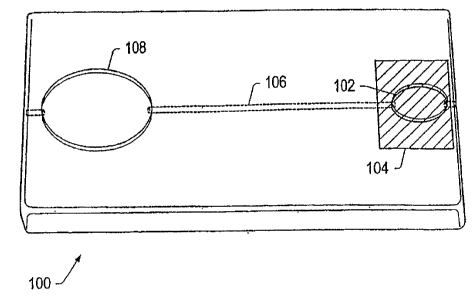
[00127] FIG. 1 depicts a perspective top view of an embodiment of a
cartridge. Cartridge 100 includes collection region 102, cover 104, fluid
channel 106,
and detection region 108. A sample may be placed in collection region 102. In
some
embodiments, other fluids (e.g., reagents and/or buffer solutions) may be
added to the
collection region and mixed with the sample. The sample may flow from
collection
region 102 through channel 106 to detection region 108.
[00128] Collection region 102 may include, but is not limited to, a
reservoir, a pad, a channel, a capillary, a tube, a vacuum collection tube
(e.g., a
Vacutainer commercially available from Becton, Dickinson Company Franklin
Parks, New Jersey, USA), an opening in the cartridge, or combinations thereof.
In
some embodiments, collection region 102 is a portion of the detection system
on
which sample is applied. In certain embodiments, collection region 102 is a
membrane.
[00129] In some embodiments, cover 104 is removable. Cover 104 may
cover a portion or all of collection region 102. The use of cover 104 is
optional.
Cover 104 may be positioned manually or automatically. In some embodiments, an
analyte-detection system automatically positions the cover over the collection
region
-21-
CA 02651872 2008-11-10
WO 2007/134191 PCT/US2007/068704
after the cartridge is positioned in the system. Cover 104 may be a flap
coupled to the
cartridge that may be moved to uncover or cover the collection region, as
desired.
Cover 104 may be moved in a sliding motion to cover or uncover the sample
collection region. Cover 104 may seal the sample collection region and inhibit
contaminants from entering the sample collection region. In some embodiments,
the
cover may include an opening. Cover 104 may at least partially contain
biological
waste and/or hazardous materials in the cartridge. In some, embodiments, the
cover
may substantially contain biological waste and/or hazardous materials in the
cartridge.
In some embodiments, the cover may include an adhesive strip, an absorbent
pad, a
non-removable plug, a swinging window, a film, a nylon filter or combinations
thereof.
[00130] In some embodiments, it may be desirable to inhibit sample
from flowing towards a detection region. For example, after a predetermined
amount
of sample flows towards the detection region, it may be desirable to inhibit
more of
the sample from flowing towards the detection region. Cover 104 may inhibit
undesired additional sample from flowing towards a detection region by
absorbing
sample from the collection region.
[00131] In some embodiments, a cartridge and/or a body of the
cartridge are formed of one or more layers. In certain embodiments, one or
more
layers seal one or more components in the cartridge. Layers may be coupled,
sealed,
and/or bonded together to form the cartridge. The cartridge body may include
more
than three layers or more than four layers coupled together.
[00132] FIG. 2 depicts an exploded view of an embodiment of a
cartridge formed of layers. Cartridge 100 may include top layer 110, channel
layer,
112, sample layer 114, reservoir layer 116, and support layer 118.
[00133] Top layer 110 may include opening 120. Samples may be
deposited on sample layer 114 through opening 120. Top layer 110 and support
layer
118 may seal cartridge 100. In some embodiments, each of the layers may
include
more than one layer coupled together.
[00134] In some embodiments, sample layer 114 may be positioned
between one or more channel layers 112 and reservoir layer 116. Sample layer
114
-22-
CA 02651872 2008-11-10
WO 2007/134191 PCT/US2007/068704
may include collection region 102 and/or one or more reagent regions 122.
Collection
region 102, one or more fluid channels 106, and/or reagent regions 122 may be
at
least partially contained in more than one layer of a body of cartridge 100.
[00135] Reservoir layer 116 may be positioned proximate sample layer
114. Reservoir layer 116 may collect sample and/or one or more fluids passing
through the cartridge during use. Reservoir layer 116 may include one or more
reservoirs 124, 124' that collect sample and/or fluid passing through the
cartridge
(e.g., an overflow reservoir and/or a waste reservoir). In some embodiments,
reservoirs may extend through more than one layer. For example, reservoir 124
may
extend through channel layer 112 and sample layer 114.
[00136] Channel layer 112 may be positioned above sample layer 114.
In some embodiments, an additional channel layer may be positioned below a
reservoir layer. In certain embodiments, one or more channel layers may be
positioned above or below one or more sample layers and/or one or more
reservoir
layers. Channel layer 112 may include a plurality of channels coupling various
components of cartridge 100. One or more channels 106 may allow fluid to flow
within a layer and/or from one layer to another layer.
[00137] In some embodiments, channels are positioned in more than
one layer of a cartridge. Positioning a channel in more than one layer may
change an
elevation of the channel enough to enhance sample and/or fluid to flow in
and/or
through the cartridge. Channels may be coupled to two or more locations in or
on a
cartridge. In some embodiments, one or more channels are a part of one or more
fluid
delivery systems.
[00138] In some embodiments, one or more channels couple a
collection region to a detection region, one or more detection systems, and/or
one or
more overflow reservoirs. Channels may couple one or more fluid delivery
systems
to a collection region, a detection region, one or more detection systems,
and/or one
or more reservoirs (e.g., overflow reservoirs and/or one or more waste
reservoirs).
Two or more channels may be coupled such that they intersect and fluid may
optionally flow through more than one channel; however, the size, the
elevation,
and/or the inside material of the intersecting channel may affect which
channel a fluid
- 23 -
CA 02651872 2008-11-10
WO 2007/134191 PCT/US2007/068704
may flow through and/or may selectively direct fluid flow. Channels or a
portion of a
channel may promote and/or inhibit fluid flow in or on the cartridge.
[00139] The size and/or the elevation of a channel may selectively
direct fluid flow through the channel. Fluid may flow preferentially through a
channel that is wider before flowing through narrower channels, thus the fluid
may be
inhibited from flowing in channels narrower than other proximate channels. In
some
embodiments, a portion of the fluid may flow into a narrower channel, while
another
portion of the fluid flows into a channel wider than the narrow channel. In
some
embodiments, some channels may have a cross-sectional area larger than a cross-
sectional area of other channels of a cartridge. Fluid may flow through the
channel
with the largest cross-sectional areas prior to flowing through channels with
smaller
cross-sectional areas. Fluid may be inhibited from flowing into a channel,
when the
channel has a smaller cross-sectional area than proximate channels.
[00140] In some embodiments, channels include changes in elevation.
A portion of a channel may be positioned in a first layer of a cartridge while
another
portion may be positioned in a second and/or third layer of a cartridge. A
channel
may have an elevation gradient along an axis parallel to fluid flow. Changes
in
elevation of a channel may promote, facilitate, and/or increase fluid flow in
or on a
channel. Elevation changes may inhibit fluid from flowing into a channel.
[00141] In some embodiments channel properties may affect fluid flow
in the channels. At least a portion of a channel may selectively direct fluid
flow in
one or more channels. A channel may be formed of a material, coated with a
material
or have material deposited on a surface of a portion of the channel that
selectively
directs fluid flow in one or more channels. For example, a channel may be at
least
partially formed of a hydrophilic material to promote aqueous fluid flow in
the
channel. A channel may be at least partially formed of a hydrophobic material
to
inhibit aqueous fluid flow in the channel. In some embodiments, portions of a
channel may be coated with a hydrophilic and/or hydrophobic material. A
material
that defines at least a part of the channel may be hydrophilic. A channel
coupled to a
collection region may be partially made of a hydrophilic material to allow an
aqueous
sample to be drawn from the collection region. In some embodiments, channels
-24-
CA 02651872 2008-11-10
WO 2007/134191 PCT/US2007/068704
partially made of a hydrophobic material may inhibit aqueous fluid flow, thus
a waste
region may not be needed.
[00142] Channels may be formed of or coated with a hydrophilic
material and/or the elevation of the channel may promote fluid flow towards
the
detection region. In some embodiments, a channel releasing fluid into the
detection
regions and/or a detection system is at least partially formed of a
hydrophilic material
to promote laminar flow in the channel. Laminar flow of fluid in the channel
may
cause matter (e.g., particles, cells, or other matter) in the sample to be
evenly
distributed across a surface of a portion of a detection system (e.g., a
membrane of a
membrane-based detection system).
[00143] FIG. 3 depicts an embodiment of a cartridge that includes
channels having different elevations. Cartridge 100 may include channels 106,
125,
126, 126', 128, 130, collection region 102, reagent regions 122, 122',
detection region
108, overflow reservoir 132, waste reservoir 134, and connectors 136.
[00144] Sample deposited in collection region 102 may flow through
channel 106 toward detection region 108. Channel 106 includes metered volume
portion 138. Metered volume portion 138 may be a part of the channel. In some
embodiments, the metered volume portion is coupled to the channel and/or the
collection region. Metered volume portion 138 may have a diameter greater than
diameters of proximate channels. If metered volume portion 138 reaches a
predetermined amount of fluid (e.g. sample), fluid may flow towards overflow
reservoir 132 through channel 125. In some embodiments, substantially all of
an
introduced sample flows out of collection region 102, into metered volume
portion
138. Excess introduced sample will enter overflow reservoir 132 if the metered
volume portion is filled. In some embodiments, overflow region 132 is coupled
a
waste region. Overflow reservoir 132 includes vent 140 to promote fluid flow.
[00145] Vents 140 may be positioned proximate one or more collection
regions, metered volume portions, waste reservoirs, overflow reservoirs,
and/or in
channels coupled to fluid delivery systems. Vents 140 may allow gas to escape
from
cartridge 100 as fluids pass through or on one or more channels or layers of
the
cartridge. Vents 140 may inhibit pressure in the channels of the cartridge
from
-25-
CA 02651872 2008-11-10
WO 2007/134191 PCT/US2007/068704
becoming greater than ambient pressure. Vents 140 may promote fluid flow in
cartridge 100 by releasing pressure associated with the passage of pressurized
fluids
through the channels. Vents 140 may facilitate laminar flow of fluids in
cartridge
100. In some embodiments, vents 140 are designed to inhibit release of fluids
through
the vent. It may be desirable to limit release of liquids while allowing gas
to escape
from the cartridge to contain fluids (hazardous reagents and/or biological
samples) in
the cartridge.
[00146] Channel 106 has different elevations. Different elevations in
the channel may inhibit fluid from flowing into detection region 108. It may
be
desirable to require a sample to be pushed towards a detection system rather
than
allowing a sample to flow towards a detection system without applied pressure
for
many reasons. For example, it may be desirable to allow the sample to mix and
interact with reagents prior to entering the detection region. Channel 106 may
promote fluid flow towards the overflow region. In certain embodiments,
channel
106 may have a negative pressure so that fluids are drawn into the channel. In
some
embodiments, a channel coupled to a collection region may have a negative
pressure
to draw the sample into the channel.
[00147] Fluid may be delivered to cartridge 100 from one or more fluid
delivery systems connected to the cartridge by connectors 136. Connectors may
include, but are not limited to, tubing, quick-disconnect connections, and/or
locking
connectors. It should be understood that any of the various embodiments of
fluid
delivery systems described herein and/or other fluid delivery systems known in
the art
may be incorporated with or coupled to cartridge 100.
[00148] Fluid enters channel 126, 126' and passes through and/or over
reagent regionsl22, 122'. In some embodiments, the reagent region may be a
pad, a
channel, a depression and/or a reservoir. In some embodiments, the reagent
regions
may be a part of the fluid delivery system. In some embodiments, the reagent
regions
are channels, which are a part of a fluid delivery system. Reagent regions
122, 122'
may include dried reagents, anti-coagulants, and/or visualization agents. In
some
embodiments, reagents, buffers and/or visualization agents are dried on or in
a pad
positioned in or on reagent regions 122, 122'. In some embodiments, reagents
and/or
-26-
CA 02651872 2008-11-10
WO 2007/134191 PCT/US2007/068704
visualization agents on and/or in the reagent regions 122, 122' may be
reconstituted by
fluid passing over and/or the through reagent region.
[00149] Channels 128, 130 may allow fluid to flow from the bottom
surface of reagent regions 122, 122' to other components of cartridge 100. In
some
embodiments, inlet and outlet channels to the reagent regions may be
positioned such
that fluid is forced to pass through, on, and/or over reagent regions 122,
122'. In
some embodiments, additional fluid delivery systems are positioned proximate
the
reagent regions.
[00150] The fluid delivery system may be controlled to allow fluid to
pass across the reagent region 122, enter metered volume portion 138, and then
enter
detection region 108. Reagents and/or visualization agents in reagent region
122 may
be reconstituted by the fluid from the fluid delivery system and may react
with the
sample. The fluid delivery system may be controlled to allow a predetermined
volume of fluid to pass through detection region 108. In some embodiments,
fluid
from a fluid delivery system may pass over a detection system of the cartridge
while
the sample incubates on the detection system and/or a membrane of the
detection
system.
[00151] Channels 128, 130 intersect channel 106, and fluid and/or
sample from these channels enters detection region 108 via channel 106.
Detection
region 108 may include viewing window 142. Viewing window 142 may be optically
coupled to a detection system. Viewing window 142 may be positioned in or on
the
cartridge. Viewing window 142 may be a portion of a detection system. For
example, viewing window 142 may be a portion of a top member of a membrane-
based detection system located in the detection region. Viewing window 142 may
be
made of a material transparent to visible or ultraviolet light. Viewing window
142
may include or be composed of a material that acts as a filter that only
allows certain
wavelengths of light to pass. Viewing window 142 may include a lens that
assists in
focusing light onto a portion of a detection system and/or onto one or more
detectors.
A detector may capture an image or light from a detection system through
viewing
window 142.
-27-
CA 02651872 2008-11-10
WO 2007/134191 PCT/US2007/068704
[00152] Detection region 108 and/or a detection system in the detection
region may be coupled to waste reservoir 134 to allow fluids flowing through
the
detection system to pass into the waste region. Waste reservoir 134 may be,
but is not
limited to, a container, a depression, or an opening. Waste reservoir 134 may
be
coupled to, positioned in, or positioned on the cartridge. By allowing fluids
to flow
towards a waste reservoir after use, all fluids in the cartridge may be
contained within
the cartridge. A contained waste reservoir may minimize health and safety
hazards
due to handling of and/or exposure to the sample and/or fluid.
[00153] Waste reservoir 134 may include cap 144. Cap 144 allows a
user to remove fluids from the waste region and/or release pressure from the
waste
region. All or a portion of cap 144 may be removable. Cap 144 may have a
variety
of shapes and/or configurations (e.g., round, oval, threaded and/or tapered).
A cap on
a waste reservoir may allow the waste reservoir to be pressurized so that
fluids may
be drawn towards the detection system and/or waste reservoir. A waste
reservoir may
include vent 140 that may inhibit a build up of pressure in the waste
reservoir.
.[00154] In some embodiments, a fluid delivery system facilitates
transport of fluid or sample from one location to another location in or on
the
cartridge (e.g., from a first location in or on the cartridge to a second
and/or third
location in or on the cartridge). In certain embodiments, a fluid delivery
system
delivers reagents, buffer, and/or visualization agents to the detection
system. The
fluid delivery system may facilitate transport of at least a portion of the
sample from
the sample collection region to the detection system. The fluid delivery
system may
couple and/or include channels that couple different regions of the cartridge.
For
example, the fluid delivery system couples the collection region to the
detection
system. The fluid delivery system may couple the collection region to the
detection
system and/or to one or more waste reservoirs. In some embodiments, the fluid
delivery system includes channels that couple components of the analyte-
detection
system to each other.
[00155] FIG. 4 depicts an embodiment of cartridge 100 with two fluid
delivery systems. Cartridge 100 may include channels 106, 125, 126, 126', 128,
130,
collection region 102, reagent regions 122, 122', detection region 108,
overflow
reservoir 132, waste reservoir 134, fluid delivery systems 150, and vents 140.
Fluid
- 28 -
CA 02651872 2008-11-10
WO 2007/134191 PCT/US2007/068704
delivery systems 150 include fluid packages 152, 152' and reservoirs 154.
During
use, sample may be released from collection region 102, flow through channel
106
and enter detection region 108. Channel 106 may include metered volume portion
138.
[00156] Fluid packages 152, 152' may be opened at predetermined
times (e.g., simultaneously or one at a time) to allow fluid (e.g., a buffer,
reagent
solution or visualization agents) in the fluid package to be released into
channel 126,
126'. The released fluids may pass over reagent regions 122, 122' before a
portion of
sample in channel 106 reaches detection system 108. For example, a portion of
a
sample is placed in collection region 102 and released into channel 106 after
fluid
from one of fluid packages 152 flows over and/or through reagent region 122.
Alternatively, a portion of sample is placed in collection region 102 and
released into
channel 106 before and/or simultaneously as fluid from one of fluid packages
152'
flows over and/or through reagent region 122. In some embodiments,
substantially
the entire excess introduced sample flows out of collection region 102 and
into
overflow reservoir 132 via channel 125. A size of overflow reservoir 132 may
allow
fluid from more than one assay to be collected during use.
[00157] Fluid from reagent region 122 flows through channel 128,
enters into channel 106, and then enters detection region 108. In some
embodiments,
channel 128 and channel 106 are the same channel. Channel 126' delivers and/or
directs fluid flow from fluid delivery system 150, across and/or through the
reagent
region 122', and into channel 130. Channel 130, which intersects channel 106,
directs
fluid from reagent region 122' to a position in channel 106 such that the
reagents from
reagent region 122' mix with a portion of the sample and/or fluid in channel
106 prior
to entering detection region 108. In some embodiments, channel 130 is a part
of
channel 106.
[00158] Vents 140 may be positioned in or on cartridge 100. Vents 140
may be a part of waste reservoir 134 or a part of one or more channels (e.g.,
channel
106).
[00159] In some embodiments, valves are used to control fluid flow
through the cartridge. Valves may be positioned on or in the cartridge. Valves
may
-29-
CA 02651872 2008-11-10
WO 2007/134191 PCT/US2007/068704
direct, control, and/or restrict fluid flow. Active or passive valves may be
positioned
in channels. Valves may include, but are not limited to, pinch valves,
pressure valves,
electromagnetic valves, and/or temperatures valves.
[00160] In some embodiments, a temperature-controlled valve may be
used. A temperature-controlled valve may include a fluid, such as but not
limited to,
water that is at least partially frozen in a channel to prevent further fluid
from passing
through the channel. To open the valve, heat is applied to the frozen fluid to
melt the
fluid. A temperature-controlled valve includes, in some embodiments, a
material that
is a solid at room temperature (e.g., paraffin or wax). To open a channel,
heat may be
applied to the solid in the channel to melt the solid material.
[00161] In certain embodiments, a valve is hydraulically activated. In
some embodiments, pressurized fluid (e.g., air or water) is used to open or
close a
valve. Pressure may be transferred via a gas or liquid in a channel to another
location
in the cartridge. The gas or liquid may be used to compress a drum and/or
close a
valve. In some embodiments, valves surrounding a portion of a channel having
negative pressure inhibit equalizing the negative pressure until desired.
[00162] FIG. 5 depicts cartridge 100 depicted in FIG. 4 with valves 156.
Valves 156 are positioned after collection region 102 and after metered volume
portion 138. Valves 156 may be used to direct fluid flow from collection
region 102
to detection region 108. Valves 156 may be positioned at various other
locations in or
on cartridge 100.
[00163] FIG. 6 depicts an embodiment of a pinch valve. Pinch valve
158 may include one or more layers 160, 162, 164 and channel 166. Layers 160,
162,
164 may be positioned over a surface of cartridge 100. In some embodiments,
the
layers are incorporated into the cartridge. Channel 166 may be an opening in
cartridge 100.
[00164] Layer 162 may be coupled to layer 160 and layer 164. Surfaces
of layers 160, 164 may be composed of materials including, but not limited to,
thermal bond film, pressure sensitive adhesive, or other adhesive materials.
Layer
162 may be adhered to layers 160, 164 (e.g., using a heat sealing process). In
some
embodiments, layer 164 forms a wall of channel 166. Layer 162 may be designed
so
-30-
CA 02651872 2008-11-10
WO 2007/134191 PCT/US2007/068704
that pressure applied to a surface of layer 162 causes the layer to deform
(e.g., layer
162 flexes). Deformation of at least a portion of layer 162 may at least
partially
obstruct channel 166 as layer 162 is forced into channel 166 by the applied
pressure.
Layer 162 may be formed of any material that exhibits flexibility when
pressure is
applied to the layer (e.g., formed of an elastomer material).
[00165] Valves may be activated manually or automatically. In some
embodiments, an analyzer system automatically opens or closes the valves.
Actuators
may be coupled to the analyte-detection system to open and/or close the
valves. In
some embodiments, an actuator is positioned above the cartridge to apply
pressure to
a valve through an opening in the cartridge. In some embodiments, an actuator
is
positioned below the cartridge to apply pressure to a valve through an opening
in the
cartridge. In some embodiments, actuators are designed to open fluid delivery
systems. In some embodiments, a metered volume of a sample including
particulate
components (e.g., cellular components) may be defined within a cartridge by
actuation of one or more valves (e.g., pinch valves).
[00166] In some embodiments, actuation is used to release liquids or
gas from a fluid delivery system. Liquids and/or gas may be pressurized into
or in the
fluid delivery system. An actuated fluid delivery system may be actuated from
a top
surface, a bottom surface, and/or a side surface of the cartridge. For
example, a
cartridge may be loaded in a housing of an analyte-detection system with
actuators.
Actuators are then automatically, semi-automatically, or manually aligned with
actuation points of the cartridge. A cartridge positioning system may
facilitate
cartridge placement into a position such that actuation points are aligned
with
actuators. Actuation points may be positioned on top, bottom, and/or side
surfaces of
a cartridge. For example, when a cartridge is positioned in the housing of an
analyte-
detection system, actuators may be positioned below the cartridge.
[00167] FIG. 7 depicts a perspective top view of a cartridge 100 with an
actuator system. The actuator system may include actuators 168, 168', 169,
169' and
structure 170. Structure 170 may be designed to move from one side of a
cartridge to
another side a cartridge 100, along a surface of the cartridge, to facilitate
actuation of
various valves and/or fluid delivery systems. Structures 170 may be positioned
at
various points on cartridge 100. As shown, structures 170 are positioned
between
-31-
CA 02651872 2008-11-10
WO 2007/134191 PCT/US2007/068704
collection region 102 and detection region 108. Structures 170 may include
openings
172. In some embodiments, opening 172 is a track. Actuators 168, 168',169,
169'
may be positioned at various points on or in structure 170 or opening 172.
Actuators
168, 168', 169, 169' may move along opening 172 in structure 170, as needed.
[00168] Actuators 168, 168' are positioned over fluid delivery systems
150, 150'. Actuation of fluid delivery system 150 by actuators 168 may force
fluid to
flow towards metered volume portion 138. Actuation of fluid delivery system
150'
by actuator 168' may allow fluid to flow towards reagent region 122.
[00169] Actuators 169, 169' may be positioned over valves proximate
metered volume portion 138. Actuation of one or more of the valves proximate
meter
volume portion 138 may allow a metered volume of sample to flow into and/ out
of
metered volume portion 138. For example, actuator 169 may open the valve
between
collection region 102 and metered volume portion 138 to allow a portion of a
sample
to flow into the metered volume portion. Actuator 169' may at least partially
open the
valve between metered volume portion 138 and detection region 108 to allow a
portion of the sample to flow towards the detection region.
[00170] Structure 170 may then be moved to a different location, as
desired. In some embodiments, sample in a channel may be inhibited from
flowing
back towards a collection region by actuating a valve. In some embodiments,
one or
more actuators may be moved along an opening or a track of the structure until
the
actuator aligns with a valve. The actuator may then actuate the valve.
[00171] In some embodiments, fluid delivery systems include one or
more fluid packages. A fluid package is a package that contains a fluid used
by a
fluid delivery system. Fluid packages may include liquids or gas under
pressure.
Fluid packages contain a fluid until the package is opened. Upon opening of
the
package, fluid in the fluid package may be at least partially released. A
fluid package
may contain a fluid until an activation pressure is applied to the fluid
package. An
activation pressure may be the pressure required to release at least a portion
of fluids
from the fluid package. An activation pressure may be the pressure required to
rupture the package of the fluid package. Upon application of an activation
pressure
to the fluid package, at least a portion of the fluid contained in the fluid
package will
-32-
CA 02651872 2008-11-10
WO 2007/134191 PCT/US2007/068704
be released. In some embodiments, a fluid package is activated (e.g., opened)
by heat
or an electromagnetic signal.
[00172] In some embodiments, fluid packages contain liquids, such as
one or more buffers (e.g., phosphate buffers), one or more solvents (e.g.,
water,
methanol, ethanol, and/or THF), one or more reagents, and/or one or more
visualization agents. Positioning one or more liquids required for analysis in
or on a
cartridge may make the fluids more accessible during use and enhance usage of
the
cartridge. Pre-packaged liquids may limit exposure to the liquids resulting
from
selection and/or mixing of solutions during use. Pre-packaged liquids may
enhance
time of analysis from sample collection to analysis of the sample. Placing the
liquids
required for analysis in fluid packages may increase stability and/or shelf
life of a
cartridge that includes an actuated fluid delivery system. Additionally, fluid
packages
may allow the cartridge to be stored at room temperature rather than requiring
refrigeration.
[00173] In some embodiments, a fluid package includes a solvent. The
solvent in a fluid package may be released from the fluid package and flow
over one
or more reagent pads that include buffer chemicals, reagents, and/or
visualization
agents. A cartridge including solvent filled fluid packages and dried buffers,
reagents,
and/or visualization agents may increase the stability of the cartridge since
dried
buffers, reagents, and visualization agents may be more stable and/or may have
a
greater shelf life than aqueous solutions.
[00174] In some embodiments, a fluid package delivers air or another
gas to the cartridge. Gas released from a fluid package may assist in
transporting a
fluid and/or a sample through and/or in the components and/or channels of the
cartridge.
[00175] In certain embodiments, a fluid package is designed to be filled
with fluid with substantially few or no air bubbles. A fluid package may be
designed
to inhibit release of air bubbles or gas within a fluid package into a
cartridge channel
or component during partial or full compression and/or actuation of the fluid
delivery
system.
-33-
CA 02651872 2008-11-10
WO 2007/134191 PCT/US2007/068704
[00176] In some embodiments, a fluid package is designed to release at
least 80 percent of liquid or gas contained in the fluid package. A fluid
package may
include about 1 mL to about 500 mL of fluid. In certain embodiments, a fluid
package has a shelf life of at least 2 years and/or has a volume loss of less
than 5
percent of the original volume during a 2-year period.
[00177] A fluid package may be, but is not limited to, a pouch,
container, and/or chamber. The fluid package may be formed from plastic
materials.
Plastic material may allow the fluid package to deform and release fluid. Once
the
fluid is released the plastic fluid package does not attempt to reform, thus
creation of
at least a partial vacuum is inhibited. Creation of at least a partial vacuum
may draw
fluids and/or gas back into the fluid package.
[00178] In some embodiments, a fluid package may be deformable in a
controlled manner. The fluid package may be formed of a material that allows
the
fluid package to be deformed and/or compressed (e.g., elastomeric material). A
deformable/compressible material may allow a fluid package to be transported,
stored,
and/or positioned without breakage.
[00179] A fluid package may be made of materials including, but not
limited to, polyvinyl chloride (PVC), polyvinylidene chloride (PVDC),
polyethylene
(PE), rubber, polypropylene (PP), polyacrylonitrile (PAN), cyclic olefin
copolymer
(COC), fluoropolymer films, foil (e.g., aluminum foil or plastic foil),
adhesive tapes,
or combinations thereof.
[00180] In some embodiments, a fluid package may be formed of a first
material and a second material, where a second material is designed to rupture
or
break before the first material when pressure is applied to the fluid package.
In some
embodiments, a wall of the fluid package may be formed of layers of
polypropylene
and cyclic olefin copolymer.
[00181] A fluid package may be formed of a material compatible with
the fluid it is designed to contain. A fluid package may be formed of a
material that
will not leach into the fluid contained within the fluid package. In certain
embodiments, a fluid package includes a layer that couples the fluid package
to the
-34-
CA 02651872 2008-11-10
WO 2007/134191 PCT/US2007/068704
cartridge. The layer may be formed of a material capable of bonding (e.g.,
adhesive
material) to acrylic, plastics, and/or other materials used to fonn a
cartridge body.
[00182] A wall of a fluid package may be designed to have a weak
portion (e.g., a burst point). The weak wall portion may rupture when a
predetermined amount of pressure is applied to the fluid package. Fluid may be
released from a fluid package when by applying sufficient pressure to the
package to
cause the weak wall portion to rupture. The location of the weakened wall
portion
may be aligned with or coupled to a channel and/or component opening. A fluid
package may be designed with a burst point or point at which fluid is released
of
about 3 psi to about 7 psi.
[00183] FIG. 8 depicts a side view of an embodiment of a fluid
package. FIG. 9 depicts a top view of the embodiment of the fluid package
depicted
in FIG. 8. Fluid package 152 may be coupled to, at least partially positioned
in, or at
least partially positioned on cartridge 100. As depicted in FIG.9, fluid
package 152
may include layer 174. Layer 174 may be made of material (e.g., adhesive) that
allows fluid package 152 to couple to cartridge 100. Fluid package 152 may be
at
least partially filled with liquid. Fluid package 152 may include liquid 176
and gas
178. Examples of gas 178 are air, nitrogen, and/or argon. A portion of a wall
of fluid
package 152 may include a burst point. As pressure is applied to the fluid
package
152, wall 180 of fluid package 152 may rupture at the burst point. Once fluid
package
152 ruptures, fluid may be released from the fluid package into channel 106.
The
rigidity of fluid package 152 may be modified to accommodate various
applications
and/or storage or transport conditions. In some embodiments, fluid and/or air
may be
contained in the fluid package by a removable adhesive strip. Removal of the
adhesive strip may allow fluid and/or air from the fluid package to be
released from
the fluid package.
[00184] In some embodiments, a cartridge includes a projection to
rupture a portion of the fluid package. The projection may be needle shaped or
any
other shape capable of perforating a fluid package. The projection may be
formed
from any suitable material such as metal, plastic, and/or silicon. FIG. 10
depicts a
side view of an embodiment of a fluid package positioned in a cartridge with a
projection. Projection 182 may be positioned proximate to a surface of fluid
package
-35-
CA 02651872 2008-11-10
WO 2007/134191 PCT/US2007/068704
152 and/or cartridge 100. Cover 184 may be positioned over fluid package 152.
FIG.
11 depicts an embodiment of rupturing the fluid package depicted in FIG. 10.
When
pressure is applied to cover 184, the cover contacts the fluid package 152
causing the
fluid package to contact projection 182. Projection 182 may rupture a portion
of fluid
package 152 causing fluids to be released channel 106.
[00185] FIG. 12 depicts cross-sectional view of a fluid package
positioned in cartridge 100. Fluid package is positioned in opening 154 of
cartridge
100. In some embodiments, fluid package is positioned on the cartridge. In
some
embodiments, one or more walls of the opening are capable of being deformed
(e.g.,
the walls flex). Cover 184 may be positioned above opening 154. Cover 184 may
be
formed of an adhesive so that fluid package 152 is retained in opening 154.
Projection 182 may be coupled to cartridge 100. Pressure applied to cover 184
may
cause wall 180 of fluid package 152 to contact projection 182 and rupture.
Fluid from
fluid package 152 may be released into channel 106. Baffles 200 positioned
proximate the bottom of opening 154 may assist in controlling flow rate of the
fluid
from fluid package 152.
[00186] In some embodiments, a fluid delivery system includes one or
more fluid packages and a reservoir. The one or more fluid packages may be
sealed
and/or positioned in the reservoir. The reservoir may be coupled to,
positioned in or
positioned on the cartridge.
[00187] FIG. 13 is a perspective view of a fluid delivery system with a
fluid package and a reservoir. Fluid delivery system 150 may include fluid
package
152, reservoir 154, and support 188. In some embodiments, support 188 is part
of a
cartridge body. Portions of the fluid delivery system may be formed of several
layers.
In some embodiments, portions of the fluid deliver system may be formed of
silicon
resin, double-sided adhesive, thermo-bond film, and/or metal foil.
[00188] FIG. 14 depicts an exploded view of fluid delivery system 150
depicted in FIG. 13. Support 188 may include support layer 189, channel layer
190,
middle layer 192, and top layer 194. Support layer 189 and/or middle layer 192
may
assist in retaining fluids in channel layer 190. Support layer 189 may be a
portion of a
cartridge. Support layer may be formed of plastic and/or glass. Channel layer
190
-36-
CA 02651872 2008-11-10
WO 2007/134191 PCT/US2007/068704
may be coupled to, or be a part of, support layer 189. Channel 106 of channel
layer
190 directs fluid flow to a collection region and/or a detection region of the
cartridge.
Channel layer 190 may include reagent regions and/or have properties described
herein. In some embodiments, the layers of fluid delivery system 150 may be
the
same as the layers in cartridge 100.
[00189] Middle layer 192 may be coupled to or be a part of channel
layer 190. Portions of middle layer 192 may include coupling agents (e.g.,
adhesive
or adhesive film) that couple the middle layer to channel layer 190. Middle
layer 192
may include opening 196. Opening 196 may direct fluid into channel 106. Middle
layer 192 may be coupled to top layer 194 using generally known coupling
techniques
(e.g., adhesive, pins, and/or screws).
[00190] Top layer 194 may seal or contain fluids in fluid package 152
and/or reservoir 154. Top layer 194 may include opening 198. Opening 198 may
direct fluid from fluid package 152 and/or reservoir 154 to channel layer 190.
Top
layer 194 may include seal 202. Seal 202 may be positioned between middle
layer
192 and top layer 194. Seal 202 may cover opening 198 of top layer 194. Seal
202
may seal fluid and/or gas in fluid package 152 and/or reservoir 154. Seal 202
may be
formed from a variety of materials (e.g., thermo-bond film, and/or foil). Seal
202
may rupture when pressure is applied to fluid package 152 and/or reservoir
154. In
some embodiments, sea1202 may be a part of top layer 194.
[00191] Top layer 194 may be coupled to or be a part of reservoir 154
using generally known coupling techniques. Reservoir 154 may include opening
203.
Reservoir opening 203 may be aligned with top layer opening 198. Top layer 194
may coupled to or be a part of reservoir 154 and/or fluid package wall 180.
[00192] Fluid package 152 may be positioned in reservoir 154. A wall
of fluid package 152 may be aligned with reservoir opening 203 and top layer
opening
196. A portion of a wall of fluid package 152 includes a burst point to allow
the fluid
package to rupture when a predetermined amount of pressure is applied to the
fluid
package and/or reservoir 154. In some embodiment, the fluid package and the
reservoir are one unit. In some embodiments the reservoir does not include the
fluid
package.
-37-
CA 02651872 2008-11-10
WO 2007/134191 PCT/US2007/068704
[00193] FIG. 15 depicts a perspective cut-away view of the reservoir of
fluid delivery system 150 depicted in FIG. 13. A diameter of top layer opening
198
and/or the reservoir opening may be less than, equal to, or greater than a
diameter of
than middle layer opening 196. As depicted, seal 202 has been torn to allow
fluid to
flow to channel 106 in channel layer 190. A center of seal 202 may be directly
aligned or offset with a center of top layer opening 198.
[00194] FIG. 16 depicts a cut-away perspective view of top layer 194
and reservoir 154 containing fluid package 152 as depicted in FIG. 13. FIG. 17
depicts a top view of fluid reservoir 154. As seen in FIG. 17, seal 202 is
offset from
top layer opening 198 in top layer 194. Offsetting seal 202 may facilitate the
rupturing of the seal when a predetermined amount of pressure is applied to
the fluid
package and/or reservoir by creating a weak point in the seal.
[00195] A center of the seal may be offset from the center of the top
layer opening by a distance ranging from about 0.2 mm to about 2 mm, about 0.3
mm
to about 1.5 mm, or about 0.4 mm to about 1 mm. When the center of the seal is
offset from the center of the top cover opening by about 0.25 mm, a burst
point of the
seal may rupture at a pressure of about 1 psi to at most 10 psi, from about 3
psi to
about 8 psi, or from about 5 psi to about 7 psi. In contrast, the burst point
of the seal
may rupture at a pressure of greater than 10 psi when a center of the seal is
aligned
with the center of the top cover opening.
[00196] In some embodiments, the pressure required to rupture a fluid
package is lowered by varying the materials used to create the seal,
decreasing the
surface area of the seal in a strategic location, decreasing the bonding
temperature of
the seal, and/or decreasing the time of heat sealing the seal to the top layer
and/or the
reservoir. Application of force to the reservoir and/or the fluid package may
change
the internal pressure in the reservoir and/or the fluid package enough to
cause the seal
to rupture or separate from the top layer. Rupturing or separating the seal
from the
top layer allows fluids in the reservoir to pass through the reservoir
opening, the top
layer opening, and/or the cover layer opening and into the channel layer.
[00197] In some embodiments, a fluid package is coupled to a structure
(e.g., a planar support or a cartridge). The structure may provide support for
the fluid
-38-
CA 02651872 2008-11-10
WO 2007/134191 PCT/US2007/068704
package. FIG. 18 depicts an embodiment of fluid delivery system 150 that
includes
fluid package 152 coupled to support 188 (e.g., a cartridge). FIG. 19 depicts
an
exploded view of fluid delivery system 150 depicted in FIG. 18. Support 188
may
include support layer 189, channel layer 190 and top layer 194. Channel layer
190
may be coupled to support layer 189 and top layer 110. Channel layer 190 may
be at
least partially formed from double-sided adhesive. Channel layer may include
channel 106.
[00198] Top layer 194 and support layer 189 may seal fluids in channel
layer 190. Top layer 194 may include opening 198. Top layer opening 198 may
direct fluid from fluid package 152 to channel layer 190. Top layer 194 or a
portion
of the top layer may include a material capable of coupling the top layer to
fluid
package 152 (e.g., vinyl adhesive or other types of adhesive). In some
embodiments
top layer 194 and fluid package 152 are formed as one unit.
[00199] FIG. 20 depicts an embodiment of the fluid package depicted in
FIG. 18 and FIG. 19. Fluid package 152 may include walls 204. Walls 204 may be
formed of a material that allows the walls to be rigid while being able to
collapse.
Walls 204 may be corrugated and designed to fold. For example, walls 204 may
form
a shape similar to an accordion. Walls 204 may have limited outward
flexibility
under pressure. A corrugated fold may maximize the efficiency of the fluid
package
to deliver fluid. Walls 204 may be designed such that compression (full or
partial) of
the fluid package will not cause the base of the fluid package to flex upwards
and/or
cause the walls of the fluid package to flex outwards. In some embodiments, a
diameter of the fluid package base is larger than a diameter of the fluid
package
opening and the top layer opening. The larger base may enhance bonding of the
fluid
package to the top layer. In some embodiments, fluid package 152 may have a
rigid
and/or ridged top surface. The rigid and/or ridged top surface may allow an
actuator
to contact the fluid package without puncturing the fluid package. The
actuator may
apply pressure to the top surface to force fluid from the fluid package.
[00200] FIG. 21 depicts an exploded view of a fluid delivery system
that may be coupled to a support. Fluid delivery system 150 may include
reservoir
154, gasket 206, and seal 202. Reservoir 154 includes one closed end and one
open
end. In some embodiments, the reservoir is formed from a mold made from
Delriri
-39-
CA 02651872 2008-11-10
WO 2007/134191 PCT/US2007/068704
(DuPont, Wilmington, DE), an inflexible polymer, brass, stainless steel,
and/or
aluminum. For example, reservoir 154 may be molded from polydimethylsiloxane.
The open end of reservoir 154 may include flange 205. Gasket 206 may couple
flange 205 to sea1202. Sea1202 may be coupled to an opening in a top layer.
Gasket
206 may include burst point 208. When a predetermined pressure is applied to
reservoir 154, gasket 206 may rupture at burst point 208 causing seal 202 to
rupture
and/or tear. Rupturing of sea1202 allows fluid from reservoir 154 to flow
through the
opening in the top layer to a channel layer of the cartridge. In some
embodiments,
gasket 206 is a double-sided adhesive layer.
[00201] In some embodiments, a fluid delivery system includes a
flexible conduit with a negative pressure source. The negative pressure source
may
be a fluid package. The negative pressure source may have a pressure less than
ambient pressure. FIG. 22A depicts fluid package 152 as a negative pressure
source
before actuation. FIG. 22B depicts fluid package 152 as a negative pressure
after
actuation. When a negative pressure source is actuated (e.g., a seal is
removed, a seal
is ruptured, or a conduit is inserted in a wall or seal of the negative
pressure source),
air and/or fluid are drawn towards the negative pressure source until the
pressure
equalizes (the negative pressure source inflates). Actuating or opening a
negative
pressure source may create at least a partial vacuum in one or more channels.
[00202] A fluid delivery system may include a fluid bulb coupled,
integrated, or embedded into the cartridge. A cartridge may be designed to
incorporate commercially available fluid bulbs or custom designed fluid bulbs.
Fluid
bulbs may have various dimensions depending on dispensing volumes required
and/or
cartridge specifications.
[00203] FIG. 23 depicts an embodiment of a fluid bulb. Fluid bulb 210
may include body 211, and conduit 212. Conduit 212 may be straight, angled
and/or
tapered. Conduit 212 may include tip 214. In some embodiments, tip 214 may be
a
breakaway sealed tip. Tip may be angled 214. Tip 214 may couple or removably
couple to a cartridge.
[00204] FIG. 24 depicts an embodiment of a fluid bulb 210 coupled or
removably coupled to a channel in the cartridge. Body 211 may release liquid
176
-40-
CA 02651872 2008-11-10
WO 2007/134191 PCT/US2007/068704
upon actuation. Body 211 may be coupled, via conduit 212, to connector 216.
Connector 216 may connect fluid bulb 210 to channel 106 of the cartridge. In
some
embodiments, tip 214 may be positioned in connector 216. In certain
embodiments,
the connector may include one or more openings to allow more than one fluid
delivery system to be attached to the connector. Connector 216 may be
permanently
affixed to conduit 212. In some embodiments, connector 216 may be removably
coupled to conduit 212 and/or channel 106.
[00205] In some embodiments, a fluid delivery system may include one
or more syringes coupled, embedded, or integrated into the cartridge. Syringes
may
be used to provide fluid delivery control, volume control, and/or a secure
fluid seal to
a cartridge. A syringe may be formed from a biocompatible material. Syringes
may
have a variety of designs, such as but not limited to, the embodiments
depicted in
FIGS. 25A-25H. The dimensions of syringes 218 may vary depending on dispensing
volumes required and/or cartridge specifications. Use of a syringe in a fluid
delivery
system may offer accurate and/or precise fluid delivery. In some embodiments,
pre-
filled syringes may be positionable in a cartridge prior to use.
[00206] FIG. 26A depicts an embodiment of a cartridge that includes
syringes 217, 218, 219. Syringes 217, 218, 219 may be linearly activated
simultaneously or sequentially. Syringes 217, 218, 219 may be actuated when a
prong contacts the fluid delivery system. In some embodiments, an actuator
with
three prongs of different lengths may be actuated to release fluid from the
syringes.
Using an actuator with prongs of different lengths may allow actuation of
different
syringes at different times using a single actuation of the prongs. Since the
prongs are
of different lengths, the actuation system may be set up such that each prong
contacts
a syringe at a different, predetermined, time. As each prong of the actuator
depresses
a syringe, fluid may be released. Syringes 217, 218, 219 may deliver fluid to
various
portions of the cartridge. For example, syringe 217 may deliver a fluid toward
reagent region 122, while syringe 218 delivers fluid towards metered volume
portion
138.
[00207] An expanded view of one the end of syringe 219 is depicted in
FIG. 26B. Syringe 219 includes tip 214 positionable in connector 216. In some
embodiments, connector 216 is coupled to the cartridge. Tip 214 may be
designed to
-41 -
CA 02651872 2008-11-10
WO 2007/134191 PCT/US2007/068704
mate with connector 216. In some embodiments, a tip may include adhesive
and/or a
gasket to seal the syringe to the connector. A cartridge may include a spring
mechanism that holds the syringes in position.
[00208] In some embodiments, a metered syringe pump is used to push
and pull fluids through the system. During use, a capillary containing sample
may be
inserted into the cartridge coupled to a fluid bus. The system may then be
filled with
buffer through two lines. Using a third line, sample may be pushed into a trap
that
releases air trapped in the sample. A line may then be used to draw a
predetermined
amount of sample into the detection system. After sample analysis, the system
may
be washed with a buffer solution and waste may be transferred to a waste
reservoir
positioned in the cartridge or coupled to the cartridge.
[00209] In some embodiments, an analyte-detection system may be
used to test for multiple analytes. The analyte-detection system may include a
multi-
functional cartridge. The multi-functional cartridge may include two or more
detection systems. In some embodiments, a single cartridge or system may
include a
membrane-based detection system and a particle-based detection system. The
membrane-based detection system may be positioned upstream from the particle-
based detection system. A sample may be introduced into the cartridge or
system and
passed through the membrane-based detection system where a portion of the
sample is
retained by the membrane. The material passing through the membrane may be
passed to the particle-based detection system. Particles in the particle-based
detection
system may interact with one or more analytes in the fluid passed over the
particles.
In alternate embodiments, a particle-based detection system may be positioned
upstream from a membrane-based detection system. In certain embodiments,
particles may be coupled to (e.g., at least partially embedded in) at least a
portion of a
membrane of a membrane-based detection system. In combination, the two
detection
systems allow the presence of at least two analytes to be assessed in a single
sample at
about the same time.
[00210] FIG. 27 depicts perspective top view of an embodiment of a
cartridge that includes two detection systems. Cartridge 100 may include fluid
delivery systems 150, reagent regions 122, collection region 102, membrane-
based
detection system 220, particle-based detection system 222, and waste reservoir
134.
-42-
CA 02651872 2008-11-10
WO 2007/134191 PCT/US2007/068704
[00211] Sample may be deposited in and/or delivered to collection
region 102. In some embodiments, a filter may be positioned proximate the
collection
region to allow removal of large particles and/or coagulated matter from the
sample.
In some embodiments, fluid may be released from fluid delivery systems 150
directly
into channel 106. In some embodiments, fluid from the fluid delivery system
may
flow directly to one of the detection systems (e.g., flow directly to the
membrane-
based detection system).
[00212] Fluid may be released from fluid delivery systems 150 and pass
through reagent region 122. Reagent region 122 may include dried reagents,
anti-
coagulants, and/or visualization agents. In some embodiments, reagents and/or
visualization agents on and/or in the reagent pad may be reconstituted by
fluid passing
over and/or through reagent region 122. In some embodiments, reagent region
122
includes reagent pads that contain dried reagents, anti-coagulants, and/or
visualization
agents. A reagent pad acts, in some embodiments, as a filter and removes large
particles and/or coagulated matter from the sample.
[00213] In some embodiments, a reagent region may be positioned
proximate the collection region so that sample from the collection region may
pass
over the reagent pad and reconstitute reagents and/or visualization agents in
the
reagent region. Directly flowing sample over and/or through a reagent region
may
facilitate the time of reaction between sample and reagents and/or
visualization
agents.
[00214] After fluid flows through and/or over reagent region 122, fluid
may flow over and/or through collection region 102. A combined fluid and
sample
flows toward the membrane-based detection system 220 and particle-based
detection
system 222. In some embodiments, a combined fluid and sample passes through
the
particle-based detection system first. In certain embodiments, a combined
fluid and
sample may first pass through a first detection system for a first test and
only pass
through the second detection system based on the results of the first test.
[00215] Membrane-based detection system 220 and/or particle-based
detection system 222 may be coupled to waste region 134. Fluid may flow from
- 43 -
CA 02651872 2008-11-10
WO 2007/134191 PCT/US2007/068704
membrane-based detection system 220 and then to particle-based detection
system
222 to waste region 134.
[00216] In some embodiments, a cartridge of an analyte-detection
system may be multi-functional (e.g., used to analyze two or more analytes in
a
sample). In some embodiments, the analysis may be done simultaneously, or
substantially simultaneously. For example, a cartridge may be used to assess
WBC
count and CRP levels in a whole blood sample.
[00217] FIG 28 depicts a top view of an embodiment of multi-
functional cartridge 100. Cartridge 100 may include connectors 136, 136',
channels
106, 126, 128, 130, metered volume portion 138, collection region 102, reagent
regions 122, 122', overflow reservoir 132, membrane-based detection system
220,
particle-based detection system 222, waste reservoir 134, and vents 140.
[00218] Sample may be deposited in collection region 102. Sample
flows from collection region 102 through channel 106 and enters metered volume
portion 138. Sample may then be delivered to membrane-based detection system
220
from metered volume portion 138. Excess sample may be collected in overflow
reservoir 132.
[00219] Connectors 136, 136' may connect one or more fluid delivery
systems to the cartridges. Fluid from the fluid delivery systems flows through
channels 126 to reagent regions 122, 122', respectively. Fluid may be
delivered at
different time intervals or substantially simultaneously to the reagent
regions from
separate fluid delivery systems. In some embodiments, fluid from the fluid
delivery
system may flow directly to one of the detection systems (e.g., flow directly
to the
membrane-based detection system).
[00220] Fluid may pass through or over reagent region 122, through
channel 128 and enter metered volume portion 138. Fluid may be delivered to
membrane-based detection system 220 from metered volume portion 138. Excess
fluid and/or sample may be collected in overflow reservoir 132.
[00221] A similar fluid or different fluid that passed through or over
reagent region 122 may pass through or over reagent region 122'. Fluid from
reagent
-44-
CA 02651872 2008-11-10
WO 2007/134191 PCT/US2007/068704
region 122' flows toward membrane-based detection system 220 through channel
130.
In some einbodiments, an additional amount of sample is delivered from metered
volume portion 138 to membrane-based detection system 220 before fluid from
reagent region 122' reaches the membrane-based detection system. In some
embodiments, fluid from reagent region 122' may flow directly to particle-
based
detection system 222.
[00222] Sample and/or fluid that pass through or over membrane-based
detection system 220 is transported to particle-based detection system 222.
The
detection systems may be optically coupled to a detector and the analytes in
the
sample may be analyzed. In some embodiments, the analytes in the sample
retained
in membrane-based detection system 220 may be analyzed prior to sending the
remainder of the sample to the particle-based detection system 222. In some
embodiments, the sample may be transported to the particle-based detection
system
222 before being delivered to the membrane-based detection system 220.
[00223] Membrane-based detection system 220 and/or particle-based
detection system 222 may be coupled to waste region 134. Fluid may flow from
membrane-based detection system 220, to particle-based detection system 222,
and
then to waste region 134.
[00224] FIG. 29 depicts an exploded view of the embodiment of
cartridge 100 depicted in FIG. 28. Cartridge 100 includes top layer 110, top
layer
opening 120, sample layer 114, reservoir layer 116, reservoirs 124, support
layer 118,
and connectors 136 designed to couple to fluid delivery systems. In certain
embodiments, one or more additional fluid delivery systems (e.g., fluid
packages)
may be coupled to, positioned on or positioned in cartridge 100 to provide
fluid for
sample processing during use.
[00225] Cartridges described herein may include a membrane-detection
system. A membrane-detection system may include a membrane and, optionally, a
membrane support. The membrane may retain at least a portion of matter in the
sample, while allowing other portions of the sample to pass through the
membrane.
For example, with blood samples, a membrane may be selected that will allow
red
-45-
CA 02651872 2008-11-10
WO 2007/134191 PCT/US2007/068704
blood cells and plasma to pass through the membrane, while the membrane
retains
white blood cells.
[00226] FIG. 30 depicts an embodiment of a membrane-based detection
system. The membrane-based detection system may be coupled to, positioned in,
or
positioned on cartridge 100. The membrane-based detection system may be
integrated within a cartridge.
[00227] Membrane-based detection system 220 includes membrane 226
and membrane support 228. In some embodiments, a membrane may be designed
such that a membrane support is not necessary. For example, a thickness of a
membrane may be selected so that a membrane remains substantially planar. In
some
embodiments, the membrane is porous.
[00228] The membrane-based detection system 220 may include
housing 230 positioned on a cartridge 100. Bottom spacer 232 may position
bottom
member 234 in housing 230. Bottom member 234 may include indentation 236 to
receive membrane 226 and membrane support 228. Channel 238 in bottom member
234 may receive fluids flowing through membrane 226 and conduct the fluids to
outlet 240. In some embodiments, the outlet is coupled to a waste reservoir of
the
cartridge. Gasket 242 may be positioned between top member 244 and membrane
226. Gasket 242 may reduce leaks from the membrane-based detection system.
Inlet
246 coupled to top member 244 may allow fluids to enter the membrane-based
detection system. Top spacer 248 may be positioned between top member 244 and
fastening member 250. Top member 244 may include viewing windows 142.
Viewing windows 142 may be transparent to visible light and/or ultraviolet
light.
Fastening member 250 may keep the components of the membrane-based detection
system coupled during use. Fastening member 250 may be machined (e.g.,
threaded
and/or tapered) to mate with housing 230.
[00229] In some embodiments, a membrane-based detection system
may include layers to direct fluid flow. FIG. 31 depicts an exploded view of
an
embodiment of a membrane-based detection system with directed fluid flow. The
membrane-based detection system may include a plurality of layers positioned
in the
cartridge or on a surface of the cartridge. Membrane-based detection system
220
-46-
CA 02651872 2008-11-10
WO 2007/134191 PCT/US2007/068704
includes top member 244, top layer 252, middle layer 254, membrane 226, bottom
layer 256, and membrane support 228. Layers of the membrane-based detection
system may be coupled to each other. Top layer 252, middle layer 254, and
bottom
layer 256 may include openings 258, 260, and 262, respectively. Fluid may flow
from inlet 246 through openings 258 and 260 to and/or through membrane 226. A
portion of analytes in the fluid flowing to the membrane 226 may be retained
on the
membrane. Light may be directed to a portion of the membrane to detect
analytes in
the fluid. Fluid may flow through membrane 226, through opening 262 and out
through outlet 240 to one or more reservoirs.
[00230] In some embodiments, a cavity is formed between the top
member and the membrane. The top member may be spaced at a distance above the
membrane to form the cavity and/or the top member may have a shape such that a
cavity is formed between the top member and the membrane.
[00231] Top member 244 may be at least partially transparent to visible
light and/or ultraviolet light. Top member 244 is, in some embodiments, formed
of
PMMA. Top member 244 may include viewing window 142. In some embodiments,
a portion of top member 244 may be opaque or translucent to visible light
and/or
ultraviolet light while viewing window 142 may be substantially transparent to
visible
light and/or ultraviolet light.
[00232] Fluid may be directed towards membrane 226 through top layer
252 positioned below top member 244. A portion of top layer 252 may be formed
of
a material or materials (e.g., vinyl material and/or an adhesive) capable of
coupling
the top layer to middle layer 254. Top layer 252 may direct flow of fluid from
top
member 244 through opening 258 and towards membrane 226.
[00233] Middle layer 254 may be positioned below top layer 252.
Middle layer 254 may be formed of a vinyl material and/or adhesive. A portion
of
middle layer 254 may be formed of a material or materials (e.g., vinyl
material and/or
an adhesive) capable of coupling the middle layer to top layer 252 and/or
bottom layer
256. Middle layer 254 may be opaque or translucent to visible light and/or
ultraviolet
light. Middle layer 254 may direct fluid to flow through opening 260 toward
membrane 226.
-47-
CA 02651872 2008-11-10
WO 2007/134191 PCT/US2007/068704
[00234] Fluid that flows through membrane 226 passes through opening
262 in bottom layer 256. Bottom layer 256 may direct fluid flow through
opening
262. A portion of bottom layer 256 may be formed of a material or materials
(e.g.,
vinyl material and/or an adhesive) capable of coupling the bottom layer to
middle
layer 254. In some embodiments, opening 262 in bottom layer 256 has a size
similar
to the size of opening 260. Openings with similar sizes may allow fluid to be
retained
in the area of membrane 226 between the middle layer 254 and bottom layer 256.
[00235] Gasket 242 may be positioned below bottom layer 256 to
inhibit leaks from the membrane-based detection device. Membrane support 228
may
be positioned below gasket 242. In some embodiments, membrane support 228 may
inhibit sagging of membrane 226. Membrane support 228 may be positioned in
bottom member 234 and/or an opening of the cartridge. Bottom member 234 may
include indentation 236 to receive membrane 226 and/or membrane support 228.
Channel 238 in bottom member 234 may receive fluids flowing through membrane
226 and conduct the fluids to outlet 240.
[00236] In some embodiments, a membrane is selected depending on
the analyte of interest. The membrane may capture or retain matter in the
sample
(e.g., particles, cells, or other matter). Matter may be retained on a surface
of the
membrane and/or in the membrane. The membrane may include a thin film or layer
capable of separating one or more components from a liquid passing through the
film
or layer. The surface of a membrane may be hydrophilic to promote cell
proliferation
across the surface of the membrane. A membrane may have a variety of shapes
including, but not limited to, square, rectangular, circular, oval, and/or
irregularly
shaped. In some embodiments, a membrane includes openings (e.g., pores) that
inhibit an analyte of interest from passing through the membrane. A membrane
designed to capture substantially all of an analyte of interest may be
selected
depending on the analyte of interest.
[00237] In some embodiments, a membrane is a monolithic microchip
with a plurality of high-density holes. The monolithic microchip membrane may
be
formed from materials including, but not limited to, glass, silica/germanium
oxide
doped silica, inorganic polymers, organic polymers, titanium, silicon, silicon
nitride,
and/or mixtures thereof. Organic polymers include, but are not limited to,
PMMA,
-48-
CA 02651872 2008-11-10
WO 2007/134191 PCT/US2007/068704
polycarbonate (PC) (e.g., NUCLEOPORE membranes, Whatman, Florham Park,
NJ), and resins (e.g., Delrin ). A membrane formed of polymeric material may
include pores of a selected range of dimensions. In certain embodiments, a
membrane
is an acrylic frit. In some embodiments, a membrane is formed of multiple
layers
(e.g., at least 2 layers, at least 3 layers, at least 4 layers, or at least 5
layers) of
etchable and/or non-etchable glass. In some embodiments, a membrane is formed
from an anti-reflective material and/or a material that does not reflect light
in the
ultraviolet-visible light range. In some embodiments, a membrane includes one
or
more locking mechanisms to assist in securing placement of the membrane in or
on
the cartridge or membrane support.
[00238] In some embodiments, membranes are microsieves.
Microsieves may be manufactured from silicon materials and/or plastic
materials. In
some embodiments, a microsieve is a layered plastic microsieve.
[00239] Membranes may have a thickness from about 0.001 mm to
about 25 mm, from about 1 mm to about 20 mm, or from about 5 mm to 10 mm. In
some embodiments, a thickness of the membrane ranges from about 0.001 mm to
about 2 mm. Membranes may have a diameter from about 1 mm to 500 mm, from
about 5 mm to about 100 mm, or from about 10 mm to about 50 mm.
[00240] Pores of a membrane may have various dimensions (e.g.,
diameter and/or volume). In some embodiments, pores of the membrane may have
approximately the same dimensions. In some embodiments, membrane pores have a
pore diameter ranging from about 0.0001 mm to about 1 mm; from about 0.0002 mm
to about 0.5 mm; from about 0.002 mm to about 0.1 mm. The membrane pores have,
in some embodiments, a pore diameter of at most 0.005 mm or at most 0.01 mm.
[00241] Pores of the membrane may be randomly arranged or arranged
in a pattern (e.g., a hexagonal close-packed arrangement). Pores of the
membrane
may occupy at least 10 percent, at least 30 percent, at least 50 percent, or
at least 90
percent of the surface area of a membrane. The pores may assist in selectively
retaining matter in a sample and/or a fluid.
[00242] In some embodiments, a membrane is positioned from about
0.3 mm to about 0.5 mm below a top surface of the cartridge. In some
embodiments,
-49-
CA 02651872 2008-11-10
WO 2007/134191 PCT/US2007/068704
the membrane includes a support. In some embodiments, a membrane is designed
such that a membrane support is not needed (e.g., utilizing a membrane having
a
thickness of at least 5 mm). In some embodiments, one or more layers separate
the
membrane and the membrane support. The membrane support may facilitate
positioning of the membrane in or on the cartridge.
[00243] A membrane support may be coupled to the cartridge or
integrated within a cartridge. In some embodiments, a membrane support is used
to
maintain a membrane in a substantially planar orientation. In certain
embodiments, a
membrane support is integrated with one or more membranes. The membrane
support may be formed of the same material as the membrane. The membrane
support may be formed of materials including, but not limited to, glass,
polymers,
metal, silicon, PC, cyclic olefin copolymer (COC), nylon, and/or
nitrocellulose. The
membrane support may be, but is not limited to, a stainless steel filter or a
plastic
mesh.
[00244] A support assembly may be coupled to the membrane support
to allow the membrane and membrane support to withstand backpressures of at
least
psi. The membrane support may be selected to produce a predetermined
backpressure. When backpressure is controlled, cells may be more uniformly
distributed across a surface of a membrane. Uniform distribution of cells
across a
membrane surface may facilitate imaging of a region containing cells and/or
analyte
detection.
[00245] In some embodiments, a membrane support includes open areas
(e.g., pores or holes). Open areas in the membrane support may have any shape,
such
as substantially square and/or substantially circular. The shape of the open
areas in
the membrane support may be different than the shape of pores in the membrane.
Open areas of the membrane support may be equal to or greater than the
diameter of
the pores of the membrane. In some embodiments, a membrane support has open
areas with diameters ranging from about 0.0001 mm to about 1 mm, from about
0.0002 mm to about 0.5 mm, or from about 0.002 mm to about 0.1 mm. The open
areas have, in some embodiments, diameters of at most 0.005 mm or at most 0.01
mm.
-50-
CA 02651872 2008-11-10
WO 2007/134191 PCT/US2007/068704
[00246] FIG. 32 depicts a top view of an embodiment of a membrane
support having a parallelogram shape. Membrane support 228 may include outer
area
264 and open area 266. Open area 266 may include openings 268. Membrane
support 228 may be machined and/or fabricated such that open area 266 has
various
shapes. Various shapes of open area 266 may allow particles of different sizes
to be
removed during analysis of the analyte. Length (L) of outer area 264 may be
greater
than or about equal to width (W) of the outer area (e.g., outer area 264 may
have a
substantially square shape or a substantially rectangular shape). A length of
open area
266 may be greater than, or about equal to a width of the open area (e.g.,
open area
266 may have a substantially square shape or a substantially rectangular
shape). Open
area 266 may have dimensions that are less than the dimensions of outer area
264. In
some embodiments, an outer area of a membrane support may have a length about
4
mm to about 6 mm and a width from about 4 mm to about 6 mm. An open area of a
membrane support may have a length from about 2.5 mm to about 4 mm and a width
from about 2.5 mm to about 4 mm. FIG. 33 depicts a top view of an embodiment
of
membrane support 228 having an euclidian shape (e.g. membrane support 228 have
a
substantially oval shape or a substantially circular shape). Open area 266 may
have
dimensions that are less than the dimensions of outer area 264.
[00247] FIG. 34 depicts a perspective cross-sectional view of open area
266 of membrane support 228. Open area 266 includes top portion 270 and bottom
portion 272. Bottom portion 272 may be equal to or less than the top portion
270. In
some embodiments, a membrane support may include a top portion formed from a
silicon nitride film and a bottom portion formed from silicon. A membrane
support
may be formed from a hydrophilic and/or anti-reflective material. Forming a
membrane support from a hydrophilic material may reduce the formation of air
bubbles across the membrane and membrane support. Use of a hydrophilic
material
may also inhibit nonspecific binding of analytes. Using a membrane support
made at
least partially of anti-reflective material may enhance analyte detection.
[00248] In embodiments where the membrane support is formed from
silicon, a bottom portion of the membrane support has a thickness (T) ranging
from
about 0.001 mm to about 5 mm. For silicon membrane supports, a thickness of
the
-51 -
CA 02651872 2008-11-10
WO 2007/134191 PCT/US2007/068704
membrane support is related to a length (Lt) of the top portion 270 and a
length (Lb)
of the bottom portion 272 as represented by the equation:
T = tan(54.7) x (Lt-Lb)/2.
[00249] FIG. 35 depicts a perspective cross-sectional view of open area
266 of membrane support 228. Open area 266 includes top portion 270, middle
portion 274, and bottom portion 272. A length of middle portion 274 may less
than a
length of top portion 270 and a length bottom portion 272. Thus, an hourglass
shaped
opening is formed.
[00250] In a membrane-detection system, a fluid and/or sample in the
detection region of the cartridge may be treated with a light. Interaction of
the light
with the fluid and/or sample may allow the analyte to be detected. Light from
one or
more light sources may shine on or in at least the detection region of a
cartridge, such
as the portion of the membrane where the fluid and/or sample is retained. The
light
may allow a signal from the retained fluid and/or sample to be detected. When
light
shines on a membrane surface, some of the light may be reflected. Areas
proximate
the detection region may also reflect some of the light that shines on a
sample. Light
reflecting from the membrane surface and/or membrane support may interfere
with
obtaining an accurate reading from the detector and so it may be advantageous
to
optically couple an anti-reflective material to the membrane and/or the
membrane
support.
[00251] In some embodiments, an anti-reflective material is optically
coupled to the membrane and/or the membrane support. Alternatively, an anti-
reflective material may be a coating on a surface of the membrane and/or
membrane
support. For example a black coating on a surface of the membrane and/or
membrane
support may act as an anti-reflective coating.
[00252] In certain embodiments, a portion of the membrane and/or
membrane support may be made of an anti-reflective material. The anti-
reflective
material may be positioned above or below a membrane. An anti-reflective
material
may inhibit the reflection of light applied to analytes retained in or on the
membrane.
The anti-reflective material may absorb one or more wavelengths of light that
are
emitted by an analyte of interest. The anti-reflective material may improve
the
-52-
CA 02651872 2008-11-10
WO 2007/134191 PCT/US2007/068704
contrast of an image of at least a portion of the analyte retained in or on
the membrane
by inhibiting reflection of light.
[00253] In some embodiments, materials that form the components of
the cartridge control flow of fluids through the cartridge. In some
embodiments,
hydrophilic material is coupled to the membrane and/or membrane support.
Alternatively, hydrophilic material may be a coating on a surface of a
membrane
and/or membrane support. In certain embodiments, a portion of the membrane
and/or
membrane support is made from hydrophilic material. Hydrophilic material may
enhance flow of a fluid through the membrane. Hydrophilic material may reduce
the
formation of air bubbles across the membrane and membrane support and/or
inhibit
nonspecific binding of analytes. Hydrophilic material may attract or have an
affinity
for aqueous fluids flowing through the membrane. Hydrophilic material may be
positioned downstream of the membrane.
[00254] In some embodiments, hydrophobic material is positioned in or
on the cartridge. Hydrophobic material may repel aqueous fluid away from
surfaces
of the cartridge and cause the fluid to flow towards the membrane. For
example,
positioning a top member above the membrane forms a cavity between the top
member and the membrane. Hydrophobic material may be coupled to the top
member. The hydrophobic material may be a coating on a surface of the top
member,
and/or the hydrophobic material may form a portion of the top member. As an
aqueous sample or fluid enters the cavity, it is repelled away from the
hydrophobic
top member and flows towards the membrane.
[00255] A membrane-based detection system may be used alone or in
combination with a particle-based detection system. In some embodiments, a
particle-based detection system includes a supporting member with one or more
cavities. One or more particles may be positioned in the cavities of the
supporting
member. In some embodiments, a particle-based detection system detects one or
more analytes simultaneously using reactive particles that interact with the
analytes.
[00256] In a particle-based detection system, a particle may produce a
signal in the presence of an analyte. Particles may produce optical (e.g.,
absorbance
or reflectance) or fluorescence/phosphorescent signals upon exposure to the
analyte.
-53-
CA 02651872 2008-11-10
WO 2007/134191 PCT/US2007/068704
Particles include, but are not limited to, functionalized polymeric beads,
agarose
beads, dextrose beads, polyacrylamide beads, control pore glass beads, metal
oxides
particles (e.g., silicon dioxide (Si02) or aluminum oxides (A1203)), polymer
thin
films, metal quantum particles (e.g., silver, gold, and/or platinum), and
semiconductor
quantum particles (e.g., Si, Ge, and/or GaAs).
[00257] The particles may include a receptor molecule coupled to a
polymeric bead. The receptors, in some embodiments, are chosen for interacting
with
analytes. This interaction may take the form of a binding/association of the
receptors
with the analytes. A particle, in some embodiments, possesses both the ability
to bind
the analyte of interest and to create a modulated signal. The particle may
include
receptor molecules, which possess the ability to bind the analyte of interest
and to
create a modulated signal. Alternatively, the particle may include receptor
molecules
and indicators. The receptor molecule may posses the ability to bind to an
analyte of
interest. Upon binding the analyte of interest, the receptor molecule may
cause the
indicator molecule to produce the modulated signal. The receptor molecules may
be
naturally occurring or synthetic receptors formed by rational design or
combinatorial
methods. Natural receptors include, but are not limited to, DNA, RNA,
proteins,
enzymes, oligopeptides, antigens, and antibodies. Either natural or synthetic
receptors
may be chosen for their ability to bind to the analyte molecules in a specific
manner.
[00258] Some particle-based detection systems and particles for use in
particle-based detection systems are described U.S. Patent Application No.:
09/616,731; U.S. Application Publication Nos.: 20020160363; 20020064422;
20040053322; 20030186228; 20020197622; 20040029259; 20050136548; and
20050214863; and U.S. Patent Nos.: 6,680,206; 6,602,702; 6,589,779; 6,649,403;
6,713,298; and 6,908,770.
[00259] In some embodiments, components necessary to obtain and
assist in the analysis of a fluid and/or sample are included in a single
package as a kit.
In some embodiments, a package includes a cartridge, a sample collection
device
(e.g., a lancet, a syringe, or a needle), and one or more disinfectant wipes.
Disinfectant wipes may be used prior to using the sample collection device to
draw a
sample from a person. A disinfectant wipe may also be used by a user to wipe
portions of the analyte-detection system before or after sample analysis.
Packaging a
-54-
CA 02651872 2008-11-10
WO 2007/134191 PCT/US2007/068704
cartridge and a sample collection device together may make collection and
analysis of
samples easier for an operator. Packaging a cartridge and a sample collection
device
together may inhibit contaminants from entering the cartridge and the sample
collection device.
[00260] A package may be sealed to inhibit entrance of air (e.g. vacuum
sealed). A package may be formed from a material that has at least one of the
following properties: is waterproof, is water resistant, controls static
electricity, kills
microbes that enter the package, blocks sunlight, and blocks UV light.
Materials that
have these properties include polymeric materials or metal foils. A package
may have
a positive pressure to protect items in the package. Insulating materials,
such as
polyurethane or bubble wrap, may be placed inside a package to protect items
in the
package.
[00261] It may be desirable for the analyte-detection cartridge and/or
system to include a control to ensure that the cartridge and/or system are
operating
correctly. Long storage times and/or less than ideal storage facilities may
damage
and/or affect the quality of the cartridge and/or components of the cartridge.
[00262] In some embodiments, it is desirable to check the fluids and/or
reagents stored in the cartridge. A particle larger than cells to be detected
or other
particles in the sensor array may be placed in a detection system as a control
analyte.
For example, a control analyte includes any type of particle previously
described,
including quantum particles or dots. Control analytes may allow assessment of
a
cartridge and/or equipment used in conjunction with the cartridge, such as,
but not
limited to, light sources, detectors, analyzers, and/or computer systems. The
control
analyte may produce a result within a selected range and/or produce a result
substantially similar to an expected result from a selected analyte.
[00263] In some embodiments a control analyte is a control particle. A
control particle may be produced by coupling a known analyte to a particle.
Reagents
passing over the detection system may interact with the sample and the control
particle. When an image of the detection system is captured the control
particle is
used to determine if the cartridge is functioning properly. For example, if a
control
particle is not detected, the quality of the reagents may be determined to be
poor and
-55-
CA 02651872 2008-11-10
WO 2007/134191 PCT/US2007/068704
the cartridge and assay discarded. In some embodiments, a control particle is
distinguishable from other matter in the detection system due to the size of
the control
particle.
[00264] In some embodiments, a control analyte is stored in or
on the cartridge. For example, a bead containing a known analyte may be
designed to
produce a predetermined signal. A weak or non-existent signal from the control
analyte may indicate an improperly functioning cartridge.
[00265] In certain embodiments, a cartridge control system may
be coupled to, positioned in, positioned on or integrated in the cartridge.
The
cartridge-control system may include, but is not limited to, one or more
control
analytes, one or more buffer solutions, and one or more reagent pads
containing a
dried predetermined analyte. In some embodiments, the cartridge-control system
includes one or more fluid packages. The fluid packages may include one or
more
control analytes one or more control solutions, and/or other reagents. Prior
to
analyzing a sample, a control solution may be released from the fluid packages
and
pass over detection system.
[00266] In some embodiments, the detection system includes a control-
detection system and an analyte-detection system. The known or control analyte
may
be applied to the control-detection system and the sample may be applied to
the
analyte-detection system. If the known analyte is captured by the control-
detection
system and a predetermined signal is produced, the cartridge is considered to
be
operating properly. If the known analyte passes through the control-detection
system
but does not produce an appropriate signal, it may indicate that the cartridge
is not
working properly (e.g., due to improper storage and/or age of the cartridge).
Improperly working cartridges may be discarded prior to deposition of a sample
on
the cartridge. Once the quality of the cartridge has been confirmed, the
sample is
analyzed for analytes.
[00267] In some embodiments, a single detection system may be used
to analyze the control analyte and the sample analytes. For example, if the
known
analyte is detectable in a detection system, the detection system may then be
washed
(e.g., laterally washing matter off the surface and/or back washing matter off
the
-56-
CA 02651872 2008-11-10
WO 2007/134191 PCT/US2007/068704
surface) to remove the known analyte from the detection system. After cleaning
the
detection system, a sample may be introduced to the detection system and a
sample
analysis performed.
[00268] In some embodiments, a detection system may be washed prior
to use with fluid from a fluid delivery system. For example, a fluid package
is
coupled via a channel to a side or bottom surface of the detection system.
Fluid from
the fluid package washes the detection system such that the wash fluid, and
any
matter contained in the wash fluid, passes into an outlet channel of the
detection
region and into a waste region.
[00269] In some embodiments, an analyte-detection system is used with
different cartridges to detect a plurality of analytes. The analyte-detection
system
may include a housing. The housing may include a slot for receiving a
cartridge. In
some embodiments, the housing includes an optical platform and/or an analyzer.
[00270] In some embodiments, an analyte-detection system may include
an analyzer (e.g., a computer system). The analyzer may analyze images and/or
control the one or more components of the analyte-detection system. The
analyzer
may be coupled to the housing and/or an optical platform of the analyte-
detection
system. The analyzer and/or analyte-detection system may include a display to
show
images produced by the detector. The analyzer and/or analyte-detection system
may
include a temperature controller. A temperature controller may control
temperatures
of or around the housing or components of the analyte-detection system.
[00271] The analyte-detection system may include a cartridge
positioning system. In some embodiments, the cartridge positioning system is
included in a housing of the analyte-detection system. The cartridge
positioning
system may automatically position the cartridge so that it is optically
coupled to one
or more light sources and/or one or more detectors. In some embodiments, one
or
more detectors and/or one or more light sources are coupled or directly
attached to an
optical platform.
[00272] One or more detectors may include, but are not limited to, a
CCD detector, a CMOS detector, a camera, a microscope, or a digital detector.
One
or more detectors may detect one or more signals from an analyte. For example,
a
-57-
CA 02651872 2008-11-10
WO 2007/134191 PCT/US2007/068704
CMOS detector may be used for detection in membrane-based detection systems or
for quantitative measurements while a CCD camera detector may be used for
detection in particle-based detection systems. A signal may be represented by
one or
more wavelengths of light absorbed by: the analyte; matter retained on a
membrane; a
fluorophore; a particle, or combinations thereof. A signal may be represented
by the
fluorescence of: the analyte; matter retained on a membrane; a fluorophore; a
particle;
or combinations thereof. The detector may transform the signal to one or more
images. The images may be of: one or more analytes in one or more fluids;
samples
retained on or in one or more membranes; one or more particles of a detection
system;
or combinations thereof.
[00273] In certain embodiments, a monochromatic detector may be
used. When a monochromatic detector is used with multiple fluorophores and
excitation sources, one or more filters may be used to isolate light emitted
in a
predetermined spectrum. For example, a green filter may be used to isolate the
light
emitted from the green fluorophore, and thus an image of the detection system
may
only include material that emits green light. A red filter may be used to
isolate light
emitted from a red fluorophore.
[00274] In some embodiments, one or more light sources may emit light
of different wavelengths. For example, a light source may be capable of
emitting two
different wavelengths of light. Different wavelengths of lights may enhance
detection
of various types of analytes. In certain embodiments, different assays require
different exposure times when images of the detection systems are obtained. An
exposure time from approximately 1-5 seconds may be used.
[00275] In some embodiments, two light sources (e.g., blue and red
LED light sources) and one or more detectors may be used to assist in
detection of an
analyte in a fluid and/or sample. Each light source may emit light at a
different
wavelength. For example, two light sources may be included in an optical
platform
and different combinations of light sources may be used to detect different
analytes.
Blue and red light sources may be used for CD4 cell assays, E. coli assays, 13-
galactosidase assay (BG) assays, and cell based assays. A blue light source
may be
used for CRP, tumor necrosis factor-a (TNF-a), and BG assays. A red light
source
may be used for interleukin-6 (IL-6) assays.
-58-
CA 02651872 2008-11-10
WO 2007/134191 PCT/US2007/068704
[00276] In some embodiments, an analyte-detection system includes
several different lenses for the detection of different analytes. More than
one lens
may be used in the detection of some analytes. The lenses may be included in
an
optical platform and/or as part of a detector. Lenses of different
magnification levels
may be used in the analysis of one or more analytes. Lens magnification levels
may
include, but are not limited, 4x, lOx, and/or 20x. For example, a 10x lens may
be
used for CD4 assays, while a 4x lens may be used for CRP, TNF-a, and IL-6
assays.
Alternatively, a 4x lens and a l Ox lens are used in the detection of E. coli
and/or BG
assays.
[00277] In some embodiments, fiber optic cables are coupled to a
detection system to facilitate image capturing. In certain embodiments, fiber
optic
cables are coupled to a particle-based membrane detection system to facilitate
analyte-detection and reduce the need to adjust magnification between
detection
regions
[00278] In some embodiments, an analyte-detection system includes a
motor coupled to a lens and/or a detector. The motor may be coupled to the
housing,
the optical platform and/or a detector of the analyte-detection system. A
motor may
move the lens and/or the detector in a direction perpendicular to the plane
the
cartridge is positioned in, or the z-axis. Moving the lens and/or the detector
vertically
along the z-axis may focus the image of the detection region.
[00279] In some embodiments, a cartridge is coupled to a motor,
actuator, or a cartridge positioning system designed to move the cartridge in
the z-
direction to focus an image of the detection region. A cartridge may be moved
to
allow more than one image of analytes to be captured in more than one
detection
system. For example, a cartridge contains more than one detection region. The
area
of interest in the detection systems may be too large to be captured with one
image,
thus the cartridge may be moved horizontally or in any direction along the x-y
plane
to obtain images of the desired areas.
[00280] FIG. 36 depicts a cartridge positioned in an analyte-detection
system. Analyte-detection system 280 includes cartridge 100, housing 281 and
optical platform 282. Optical platform 282 includes detector 284, light
sources 286,
-59-
CA 02651872 2008-11-10
WO 2007/134191 PCT/US2007/068704
288, lenses 290, 292, 294, 296 and filters 298, 300, 302. Cartridge 100 may be
positioned automatically and/or manually in housing 281. Light 304 (e.g., a
white
light) from light source 286 may be collimated with lens 290, filtered to a
desired
wavelength using filter 298 (e.g., filtered to a wavelength in a blue portion
of visible
light), and directed in or on a detection system positioned in detection
region 108 of
cartridge 100. In some embodiments, light from a light source may enter the
cartridge
at an angle. For example, the light source may be positioned at a 45 angle
with
respect to the detector and/or the cartridge. Filter 298 (e.g., excitation
filters and/or
clean-up filters) may be used to narrow excitations from light emitting diodes
and/or
other light sources. For example, filter 298 may be a D467/20x filter capable
of
filtering light to a wavelength ranging from about 450 nm to about 480 nm
(e.g., 457
nm to about 477 nm). Filter 300 may be a 635/20x filter capable of filtering
light to a
wavelength ranging from about 625 nm to about 645 nm.
[00281] After light is directed into detection region 108, light 306 (e.g.,
signal) produced from interaction of the analyte with the sample may then be
obtained
using detector 284. The signal may be transformed into an image representing
the
desired analyte. In some embodiments, the image represents a membrane of the
detection system and/or one or more analytes in the fluid and/or sample.
Detector 284
includes, but is not limited to, a digital detector, a CMOS camera, or a CCD
device.
In some embodiments, moving the optical platform along the axis perpendicular
to the
cartridge while the cartridge is held static allows images of the cartridge to
be brought
into focus for the detector. Emission filter 302 may be used with detector
284. For
example, light 306 reflected from the detection region 108 passes through lens
294
and/or an emission filter 302. Lens 296 is used to collimate light 306 from
detection
region 108 and/or focus the light from the detection region to detector 284.
Emission
filter 302 may be a dual band emission filter that allows transmission between
about
504 nm and about 569 nm and between about 670 nm and about 822 nm.
[00282] Next, light 308 from light source 288 is collimated with a lens
292, filtered to a desired wavelength with filter 300, and focused on a
sample.
Emitted light 310 produced by interaction of the analyte with the sample and
emitted
from detection region 108 passes through lens 294 and/or emission filter 302
and is
collimated with lens 296 to detector 284. Detector 284 obtains the signal from
-60-
CA 02651872 2008-11-10
WO 2007/134191 PCT/US2007/068704
illumination of detection region 108 with light source 288. Emitted light 310
is
ransformed into an image representing an image of the detection region. It
should be
understood that additional light sources (e.g., a third light source, a fourth
light
source, a fifth light source, etc.) may also be used. Signals produced from
the
detection region may then be processed to produce images of a portion of the
detection region (e.g., a portion of a membrane) and/or of analytes present in
the
sample. In some embodiments, an analyzer determines the identityand/or
presence of
the analytes.
[00283] FIG. 37 depicts an alternative arrangement for an
analyte-detection system 280. Optical platform 282 includes light sources 286,
288.
Light sources 286, 288 emit light in a range from about 460 nm to about 480
nm,
from about 465 nm to about 475 nm, or from about 460 nm to about 470 nm.
During
use, detection region 108 of cartridge 100 may be positioned automatically or
manually in housing 281. Detection region 108 contains one or more detection
systems (e.g., a membrane-based detection system and/or a particle-base
detection
system). The detection system includes at least one sample and at least one
visualization agent. Light 304 from first light source 286 is collimated with
lens 290,
filtered to a desired wavelength using filter 298, reflected 90 degrees by
dichroic
mirror 312, and focused on a detection system in detection region 108 with
lens 294.
In some embodiments, the dichroic mirror is a combination of dichroic mirrors.
The
dichroic mirror may include one or more reflection bands and/or one or more
transmission bands. For example, dichroic mirror 312 may be a Z502RDC long
pass
dichroic mirror, which is a dual band dichroic mirror having 2 reflection
bands and 2
transmission bands. One reflection band of a dichroic mirror may reflect light
at a
wavelength ranging from about 463 nm to about 483 nm and transmit light
ranging
from about 502 nm to about 587 nm. A second reflection band of the dichroic
mirror
may reflect light at a wavelength ranging from 603 nm to about 637 nm and
transmit
light at a wavelength ranging from about 656 nm to about 827 nm.
[00284] Light 306 reflected and/or emitted from detection region 108
passes through lens 294, is filtered to predetermined wavelengths with filter
302 (e.g.,
a dual band emission filter), collimated with lens 296, and processed by
detector 284
to produce an image of the detected analytes.
-61-
CA 02651872 2008-11-10
WO 2007/134191 PCT/US2007/068704
[00285] Light 308 from second light source 288 is collimated with lens
292, filtered to a desired wavelength with filter 300. Filter 300 is a
different filter
than filter 298, thus light 308 has a different wavelength than light 304.
Filtered light
308 is reflected 90 degrees by dichroic mirror 314, reflected 90 degrees by
dichroic
mirror 312, and focused on or in detection region 108 using lens 294. Light
310
reflected and/or emitted from detection system 108 passes through lens 294,
passes
through dichroic mirror 312, is filtered to predetermined wavelengths with
filter 302,
is collimated by lens 296, and processed by detector 284 to produce an image
of the
detected analytes. Filter 302 may be a dual band emission filter capable of
filtering
light at two different ranges of wavelengths (e.g., a first wavelength from
about 504
nm to about 569 nm and a second wavelength from about 607 nm to 822 nm).
[00286] The signal obtained by detector 284 may then be analyzed (e.g.
using an analyzer) to determine the presence and/or identity of analytes in
the
detection region. Any number of light sources may be used in a similar manner
as
described above. It may be desirable to use a plurality of light sources to
substantially
simultaneously detect a plurality of analytes.
[00287] In some embodiments, a single light source with a beam
splitter is used instead of multiple light sources. Using one excitation
source may
reduce costs. The single light source may excite two or more visualization
agents
applied to matter captured on a membrane of a detection system of a cartridge.
The
emission of light from the detection system may be separated using one or more
dichroic mirrors and one or more detectors.
[00288] FIG. 38 is a schematic of a cartridge positioned in an analyte-
detection system with an optical platform that includes a single light source.
Analyte-
detection system 280 includes cartridge 100, housing 281, and optical platform
282.
Optical platform 282 includes detectors 284, 316, light source 286, lenses
290, 294,
296, 318, filters 302, 320, dichroic mirrors 312, 314 and shutter 322.
[00289] Light 304 from single source 286 is collimated with lens 290,
passed through shutter 322, reflected 90 degrees by dichroic mirror 312, and
focused
on detection region 108 of cartridge 100 with lens 294. Shutter 322 is
positioned
between lens 290 and dichroic mirror 312. Shutter 322 may block light from
shining
-62-
CA 02651872 2008-11-10
WO 2007/134191 PCT/US2007/068704
on detection region 108 and/on cartridge 100. Light 306 reflected and/or
emitted
from a detection system of detection region 108 may pass through lens 294,
dichroic
mirrors 312, 314, filter 302, and lens 296 where light 306 is collimated onto
detector
284. A portion of light 306, depicted as light 306', may be reflected using
dichroic
mirror 314, pass through filter 320 (e.g., a dual band emission filter), and
lens 318
where light 306' is collimated onto detector 316.
[00290] In some embodiments, an actuator is used to move a series of
different emission filters into the path of light entering a detector. The
ability to use
different emission filters allows more than one signal from the detection
region of the
cartridge to be analyzed by one detector. The use of one detector and more
than one
filter may enhance the sensitivity of a test process, allowing less sample to
be used for
an analysis of multiple analytes. Determination of the appropriate emission
filters to
position in front of the detection system may be based on data obtained from a
barcode located on the cartridge.
[00291] FIG. 39A is a schematic diagram of a cartridge positioned in an
analyte-detection system that includes an optical platform equipped with an
actuator.
The actuator is designed to position a series of filters in front of a
detector. Analyte-
detection system 280 includes cartridge 100, housing 281, and optical platform
282.
Optical platform 282 includes detector 284, light source 286, lenses 290, 294,
296,
dichroic mirror 312, shutter 322, filter holder 324, filters 302, 320, and
actuator 326.
Light 304 from light source 286 is collimated with lens 290, passed through
shutter
322, reflected 90 degrees by dichroic mirror 312, and focused onto detection
region
108 of cartridge 100 with lens 294. Light 306 reflected and/or emitted from a
detection region 108 may pass through lens 294, pass through dichroic mirror
312,
pass through filter 302 or filter 320 positioned in filter holder 324, and
lens 296 where
light 306 is collimated onto detector 284. Filter holder 324 may include
additional
emission filters depending on the analyte to be analyzed. Filter holder 324 is
coupled
to actuator 326, which is designed to move filter holder 324. Actuator 326 may
move
filter holder 324 based on a signal from detector 284 and/or an analyzer of
analyte-
detection system 280. Filter holder 324 may be positioned between cartridge
100 and
detector 284. In some embodiments, actuator 326 may move filter holder 324
such
that filter 320 may be positioned between detector 284 and detection region
108 such
-63-
CA 02651872 2008-11-10
WO 2007/134191 PCT/US2007/068704
that light 306 may pass filter 320 and into detector 284, as shown in FIG.
39B,
allowing analysis of the detection region using a different wavelength of
light. The
filter light (e.g., filtered signal) may then be analyzed in the detector to
produce an
image and/or data of analytes in the fluid and/or sample. A plurality of
images and/or
data from the fluid and/or sample may be obtained using a plurality of
emission filters
placed sequentially in front of the detector.
[00292] Analyte-detection systems described herein may be used. to
identify the presence of a plurality of analytes in a sample. Analyte-
detection systems
may be designed for detection of one or more specific analytes (e.g., cellular
components, proteins, or pathogens such as viruses, bacteria, fungi or
parasites, or
combinations thereof) typically associated with various infections, diseases,
illnesses,
and/or syndromes. Examples of diseases, illnesses, viruses and syndromes
include,
but are not limited to, AIDS, malaria, heart disease, atherosclerosis, cancer,
tuberculosis, mononucleosis, syphilis, sickle-cell anemia, herpes virus, HIV,
Good's
syndrome, or Sjogren's syndrome. Examples of herpes viruses include, but are
not
limited to, Epstein-Barr virus (EBV), cytomegalovirus (CMV), herpes simplex
viruses
1 and 2(HSVI and HSV2), varicella-zoster virus (VZV), Kaposi's sarcoma-related
virus (HHV8), herpes lymphotropic virus (HHV6), and human herpes virus 7
(HHV7).
[00293] Analysis of human blood samples may allow for early detection
of various diseases, illness, viruses and/or syndromes. For example, WBCs and
RBCs
may be separated and analyzed to determine specific diseases, illnesses,
viruses,
and/or syndromes. In some embodiments, WBCs are separated from RBCs and
immunotyped to determine the total number of various cell types in a sample
and/or
their ratio relative to other cell types. A five-part WBC differential, which
is part of a
typical complete blood count, may be used for general illness assessment. A
five part
WBC differential may sort out results based on counts of various white blood
cells in
various classes of diseases and may be used to diagnose viral, bacterial,
allergic and
immune diseases.
[00294] Samples may be analyzed by characterizing one or more
components of a blood sample, including the fluid component of whole blood,
such as
serum or plasma. Samples may also be analyzed by characterizing one or more
solid
-64-
CA 02651872 2008-11-10
WO 2007/134191 PCT/US2007/068704
components of a blood sample. Solid components of a blood sample may include,
but
are not limited to, blood cells, platelets, or pathogenic organisms (e.g.,
bacteria,
viruses, fungi, or blood-borne parasites).
[00295] In some embodiments, the cellular components of a sample
may be characterized by detecting the presence and/or expression levels of one
more
molecular groups (e.g., polypeptides, polynucleotides, carbohydrates, lipids)
typically
known to be associated or correlated with a specific trait for which the test
is being
performed. For example, a blood sample may be collected to measure the number
of
one or more specific cell types present in the sample (commonly referred to in
the art
as "cell counts"), and/or the ratio thereof with respect to one or more
different cells
types also present in the sample. Examples of the types of blood cells that
may be
detected in a blood sample include, but are not limited to, erythrocytes,
lymphocytes
(e.g., T cells and B cells), Natural Killer (NK)-cells, monocytes/macrophages,
megakaryocytes, platelets, eosinophils, neutrophils, basophils or mast cells.
In some
embodiments, various sub-populations of specific cell types within a fluid
sample are
distinguished. For example, the T cells present in a blood sample may be
further
categorized into helper (CD4+), cytotoxic (CD8+), memory (CD4/CD8 and/or
CD45RO) or suppressor/regulatory (CD4+CD25+FOXP3+) T cells. Alternatively, B
cells present in a blood sample may be further categorized into populations of
immature, mature, activated, memory, or plasma cells, based on the
immunoglobulin
isotype expressed on the cell surface, and presence or absence of various
additional
proteins.
[00296] Table I summarizes the surface expression profile of a selection
of non-limiting protein markers that may be used to classify the stage of B
cell
differentiation, where filled circles denote expression, open circles denote
lack of
expression, and partially filled circles denote partial or limited expression
of the
indicated surface marker. The presently described systems and methods are not
limited to detecting the cell types disclosed in Table 1. It should be
understood, that
the presently disclosed systems and methods may be suitably adapted to analyze
most
cell types and/or macromolecules present in a biological sample without
departing
from the spirit and scope of the presently described embodiments.
-65-
CA 02651872 2008-11-10
WO 2007/134191 PCT/US2007/068704
Table I.
Surface
Immunoglobulin Marker protein
B cell stage isotype
IgM or IgG I A IgD CD23 P lA CD38 CD25 CD10
Pre B 0 0 0 0 0 = 0 0
Immature = 0 0 0 0 0 0 0
Mature = 0 = = 0 0 = 0
Activated = = 0 = 0 0 = =
Memory 0 = 0 0 0 0 0 0
Plasma cell 0 0 0 0 = = 0 0
[00297] Analysis of a cellular composition of a sample may include
detecting the presence of one or more "surface markers" known to be expressed
on
the surface of the population of cells of interest. Certain surface markers
useful in the
differential identification of cells in a sample (e.g., in particular cells
involved in
immune responses) and/or diseases are commonly referred to as "cluster of
differentiation (CD)" antigens or CD markers, of which over 250 have been
characterized. Many of the CD antigens may also be referred to by one or more
alternative art-recognized terms. Table II lists several examples of CD
antigens, and
the cells in which they are expressed, that may be referred to using one or
more
alternative terms. The system of CD marker nomenclature is widely recognized
by
ordinary practitioners of the art. General guidance in the system of CD marker
nomenclature, and the CD expression profiles of various cells may be found in
most
general immunology reference textbooks such as, for example, in IMMUNOLOGY,
4t1i Edition Ed. Roitt, Brostoff and Male chapter 28 and Appendix II
(Mosby/Times
Mirror International Publication 1998), or in IMMUNOBIOLOGY: THE IMMUNE
SYSTEM IN HEALTH AND DISEASE, 5" Edition, Eds. Janeway et al. Appendices
I-IV (Garland Publishing, Inc. 2001).
-66-
CA 02651872 2008-11-10
WO 2007/134191 PCT/US2007/068704
Table II.
CD Identity/function Expression
Antigen
CD3 T cell receptor Thymocytes, T cells
CD4 MHC class II receptor Thymocyte subsets, T helper cells, monocytes,
macrophages
CD8 MHC class I receptor Thymocytes subsets, cytotoxic T cells
CD10 Neutral T and B-cell precursors, activated B cells, granulocytes
endo e tidase/CAALA
CD11a Integrin a Lymphocytes, granulocytes, monocytes and
macro hages
CD 11 b Integrin a Myeloid and NK cells
CD13 Aminopeptidase N Monocytes, granulocytes
CD16 FcyRIIIA/ B Neutrophils, NK cells, macrophages
CD19 B cell function/activation B-cells
CD20 Ca 2+ ion channel B-cells
CD21 C3d and EBV receptor Mature B cells
CD35 Complement receptor 1 Erythrocytes, B cells, monocytes, neutrophils,
eosinophils
CD41 allb integrin Platelets, megakaryocytes
CD45RO Fibronectin type II T-cell subsets, B-cell subsets, monocytes,
macrophages
CD45RA Fibronectin type II B cells, T-cell subsets (naive T cells), monocytes
CD45RB Fibronectin type II T-cell subsets, B cells, monocytes, macrophages,
granulocytes
CD56 NKH-1 NK cells
[00298] In some embodiments, the presently described analyte-
detection systems and methods may be used to analyze blood samples on the
basis of
the expression profile or presence of one or more macromolecules (e.g.,
proteins,
phosphoproteins, glycoproteins, polynucleotides, or variants or isoforms
thereof) that
are indicative or prognostic of certain pathological states. Types of analytes
that may
be useful diagnostic or prognostic indicators and whose plasma or cellular
expression
levels are correlated with various diseases, illnesses, viruses, and/or
syndromes
include, but are not limited to, chemokine receptor 5 (CCR5), viral DNA or RNA
sequences, certain species of plasma RNA, interferon-gamma (IFN-y), virus
particles,
early secreted antigenic target protein-6 (ESAT-6), culture filtered protein-
10 (CFP-
10), C-reactive protein (CRP), troponin-I, and TNF-a.
[00299] In some embodiments, an analyte-detection system may be
used for prognostic tests for HIV seropositive patients. HIV infects CD4+
cells (e.g.,
certain populations of T helper cells, monocytes and macrophages) by binding
to a co-
receptor CCR5. The expression level of certain CCR5 variants in CD4+ cells has
been
-67-
CA 02651872 2008-11-10
WO 2007/134191 PCT/US2007/068704
shown to correlate with viral load and progression to AIDS. The presently
described
analyte-detection systems and methods may be used to, for example, monitor
CCR5
expression in CD4+ cells in patient blood samples. This parameter may
advantageously be measured simultaneously from a single sample with one or
more
measures of HIV viral load. In some embodiments, the tests described herein
may
further measure one or more blood parameters associated with other
pathological
situations in addition to, or alternatively to, HIV infection.
[00300] In certain embodiments, an analyte-detection system may be
used to diagnose tuberculosis (TB). In some embodiments, an analyte-detection
system may be used to detect reductions in systemic CD3+ and CD4+ cells that
typically occur in TB patients. This parameter may be measured alone or in
combination with the detection of one or more soluble proteins typically
elevated in
TB patients (such as IFN-y), the mycobacterial proteins ESAT-6, CFP-10, or T
cells
populations that are reactive to ESAT-6 and CFP-10. Such applications may be
particularly suited to certain point-of-care settings and/or in resource
scarce countries
where HIV and TB comorbidity are common.
[00301] In some embodiments, an analyte-detection system as described
herein may be used to diagnose viral infections in addition to HIV. Blood
samples
from both Epstein-Barr virus (EBV) and cytomegalovirus (CMV) infected patients
exhibit increases in percentages of total T-cells, suppressor T-cells and
activated
HLA-DR+ T-cells when compared with healthy, uninfected people. Additionally,
as
seen in HIV infected patients, individuals infected with EBV and/or CMV
typically
display significantly decreased levels CD4+ T-cells as well as a decrease in
the ratio
of CD4/CD8 T cells. Blood samples from individuals infected with EBV may also
exhibit elevated levels of NK cells.
[00302] The analyte-detection systems described herein may, in some
embodiments, be adapted to readily, reproducibly, and cost effectively
diagnose a
variety of maladies endemic to geographic and/or economically disadvantaged
regions. An example of such an application is point-of-care diagnosis of
malaria in
geographic areas such as, for example, Africa, Latin America, the Middle East,
South
and Southeast Asia, and China. Currently, reliable diagnosis of malaria is
time
consuming, labor intensive, and typically involves identifying erythrocytes
harboring
-68-
CA 02651872 2008-11-10
WO 2007/134191 PCT/US2007/068704
Plasmodium parasites. Identification of such cells is typically made by
microscopic
examination of uncoagulated Giemsa-stained blood samples, possibly in
combination
with one or more serological and/or molecular diagnostic tests (e.g.,
polymerase chain
reaction), all of which require highly specialized equipment. In some
embodiments,
analyte-detection systems described herein may be sued to detect one or more
Plasmodium-specific antigens that include, but are not limited to, panmalarial
antigen
(PMA), histidine-rich protein 2 (HRP2) and parasite lactate dehydrogenase
(pLDH) in
a blood sample. In some embodiments, the analyte-detection systems presently
described may be used to monitor one or more physiological parameters
associated
with malaria. For example, a portion of the hemoglobin from Plasmodium-
parasitized
erythrocytes forms lipidized pigment granules generally referred to as
"hemozoin."
Phagocytosed hemozoin impairs monocyte/macrophage and hence immune function,
at least in part, by reducing the surface expression of MCH class II, CDl lc
and CD54
in phagocytes. Additionally, low peripheral blood monocyte counts may be
associated with patients with severe and complicated malaria. Analyte-
detection
systems described herein may be used to detect and monitor the presence and/or
quantities of these physiological parameters associated with malaria.
[00303] In some embodiments, analyte-detection systems described
herein may be used to diagnose Good's syndrome, an immunodeficiency disorder
secondary to thymoma and characterized by deficiencies of cell-mediated
immunity
and T-cell lymphopenia.
[00304] In some embodiments, an analyte-detection system may be
used to identify certain biological markers associated with increased
susceptibility to
various pathological conditions (e.g., cardiovascular disease,
atherosclerosis,
inflammation, and/or certain types of cancer). Inflammation has been
identified as an
underlying cause of atherosclerosis, a condition associated with the
deposition of
lipids on the lining of arteries that may progressively lead to serious
vascular
complications such as myocardial infarction (MI) and/or stroke. By measuring
the
concentration of certain proteins associated with inflammation (e.g., CRP)
either
alone or in conjunction with cellular profiles (e.g., WBC count), the
presently
described analyte-detection systems may be used to screen individuals at risk
for heart
attack, atherosclerosis, or other vascular diseases. Likewise, MI patients
with
-69-
CA 02651872 2008-11-10
WO 2007/134191 PCT/US2007/068704
elevated CRP levels or WBC counts are at higher risk for subsequent
cardiovascular
events. Diagnostic and prognostic tests that provide measurements for these
two
important biological parameters associated with inflammation and vascular
disease
may provide powerful diagnostic and prognostic insight, allowing healthcare
providers to make timely and appropriate therapeutic interventions. For
example, it is
recognized by practitioners of the art that individuals having elevated WBC
counts
and blood CRP levels have a greater risk for heart disease than individuals
having
WBC counts and CRP levels within normal range.
[00305] A low peripheral monocyte count in individuals with high
cholesterol is generally predictive of increase risk for developing
atherosclerosis. The
presently described analyte-detection systems may be readily and
advantageously
adapted to measure monocyte counts (CD 13+CD 14+CD45RA) associated with
cardiac
risk factors. Monocyte counts are also an important physiological parameter in
subjects with hypercholesterolemia. Analyte-detection systems described herein
may
also be used to measure the amounts of other cardiac risk factors such as
troponin I
and/or TNF-a.
[00306] A percentage of CD8+ cells and a number of monocytes in
blood have been associated with progressive encephalopathy (PE). PE is one of
the
most common complications of HIV infection in children. As antiretroviral
drugs
become more available, the number of children with PE has increased, thus it
is
desired to evaluate risk factors for PE. CD8 stained cells may be identified
using an
analyte-detection system to monitor the progress of PE.
[00307] An analyte-detection system for use in diagnostic and
prognostic applications to specific pathologies, such as for example, those
described
above, may further allow a user of the system to readily identify
characteristics in a
sample that are associated with the malady. The analyte-detection system may
include, for example, various receptor molecules (such as specific antibodies)
that
bind to cell surface markers (e.g., CD markers or other disease-associated
molecules)
or any other analyte suspected to be present in a sample that allows rapid
characterization of the sample. In some embodiments, one or more antibodies
(e.g.,
monoclonal and/or polyclonal antibodies) that specifically recognize and bind
to
-70-
CA 02651872 2008-11-10
WO 2007/134191 PCT/US2007/068704
macromolecules expressed on the surface of cells (e.g., CD or other cell
surface
markers) may be used in an analyte-detection system.
[00308] While certain specific examples of monoclonal or polyclonal antibodies
are set forth
above, it will be readily understood by ordinary practitioners of the art that
the presently
described analyte-detection systems may be used, without limitation, in
conjunction with any
type of antibody that recognizes any antigen, including, but not limited to,
commercially
available antibodies or antibodies generated specifically for the purpose of
performing the
tests described herein. Monoclonal and Polyclonal antibody design, production
and
characterization are well-developed arts, and the methods used therein are
widely known to
ordinary practitioners of the art (see, e.g., "Antibodies: A Laboratory
Manual," E. Howell and
D. Lane, Cold Spring Harbor Laboratory, 1988). For example, a polyclonal
antibody is
prepared by immunizing an animal with an immunologically active composition
including at
least a portion of the macromolecule to which the desired antibody will be
raised and
collecting antiserum from that immunized animal. A wide range of animal
species may be
used for the production of antiserum. Examples of animals used for production
of polyclonal
anti-sera are rabbits, mice, rats, hamsters, horses, chickens, or guinea pigs.
[00309] A monoclonal antibody specific for a particular macromolecule
can be readily prepared through use of well-known techniques such as those
exemplified in U.S. Patent No. 4,196,265, to Koprowski et al., which is herein
incorporated by reference. Typically, the technique involves first immunizing
a
suitable animal with a selected antigen (e.g., at least a portion of the
macromolecule
against which the desired antibody is to be raised) in a manner sufficient to
provide an
immune response. Rodents such as mice and rats are preferred species for the
generation of monoclonal antibodies. An appropriate time after the animal is
immunized, spleen cells from the animal are harvested and fused, in culture,
with an
immortalized myeloma cell line.
[00310] The fused spleen/myeloma cells (referred to as "hybidomas")
are cultured in a selective culture medium that preferentially allows the
survival of
fused splenocytes. After the fused cells are separated from the mixture of non-
fused
parental cells, populations of B cell hybridomas are cultured by serial
dilution into
single-clones in microtiter plates, followed by testing the individual clonal
supernatants for reactivity with the immunogen. The selected clones may then
be
-71-
CA 02651872 2008-11-10
WO 2007/134191 PCT/US2007/068704
propagated indefinitely to provide the monoclonal antibody of interest. In
some
embodiments, a membrane-based detection system for use in perforining WBC
counts
on a blood sample may use one or more polyclonal or monoclonal antibodies that
specifically recognize various cell types that constitute WBCs to visualize
specific
blood cells. Antibodies suitable for this purpose include, but are not limited
to: anti-
CD3; anti-CD4; anti-CD8; anti-CD16; anti-CD56; and/or anti-CD19 antibodies to
specifically recognize: T cells; T helper cells and monocytes/macrophages;
cytotoxic
T cells; neutrophils, NK cells and macrophages; NK cells; and B cells,
respectively.
[00311] In some embodiments, a membrane-based detection system is
used to assess both CD4 cell count and CD4 cells as a percentage of total
lymphocytes from a blood sample for diagnosis, staging, and/or monitoring of
infections and/or diseases. For example, samples having CD4 counts below 200
cells
per microliter may indicate specific drug therapy intervention. In certain
embodiments, comparing CD4 cell counts to CD8, CD3, and/or CD19 cell counts
may be used to assess the ratio CD4+ T helper cells with respect to cytotoxic
T cells,
total circulating T cells, B cells, or combinations thereof.
[00312] In some embodiments, a sample, such as blood or diluted
blood, is applied and/or transported to a membrane of a membrane-based
detection
system. The membrane may retain portions of the sample, while allowing other
portions of the sample to pass through. For example, the membrane may be
adapted
to retain lymphocytes, while allowing other portions of the sample, such as
water or
red blood cells, to pass through.
[00313] A combination of visualization agents may be applied and/or
transported to the membrane to allow a total number and/or different types of
lymphocytes (e.g., T cells, NK-cells, and/or B-cells) to be identified. One or
more
visualization agents may be added to the matter collected on a surface of the
detection
system. For example, visualization agents may allow the detection of anti-CD3,
anti-
CD4, anti-CD8, anti-CD16, anti-CD56 and anti-CD19 antibodies bound to their
respective CD markers on the surface of target cells. In some embodiments,
anti-
CD2, anti-CD4, and anti-CD 19 antibodies may be coupled to the visualization
agent
directly. In some embodiments, the visualization agent may be coupled to a
second
-72-
CA 02651872 2008-11-10
WO 2007/134191 PCT/US2007/068704
macromolecule that specifically binds to and recognizes the antibody bound to
the CD
marker.
[00314] In some embodiments, a first visualization agent may be used
to stain CD4+ cells present in a mixed population of cells. Additional,
distinct
visualization agents may then be used to stain the NK-cells, B-cells, and/or
other T-
cells in the mixed population. For example, a mixed population of cells in a
sample
may be stained with anti-CD4, anti-CD3, anti-CD56, and anti-CD19 antibodies to
detect CD4+ T helper cells, total T-cells, NK-cells, and B-cells respectively.
[00315] In some embodiments, fluorescent dyes (e.g., AlexaFluor dyes
from Invitrogen Corporation; Carlsbad, CA) may be coupled to antibodies to
form
fluorophore-labeled antibodies. Use of fluorophore-labeled antibodies to
visualize
cells may facilitate assessment of the sample. One or more fluorescent dyes
may be
used to label one or more cell surface markers to facilitate assessment of a
desired
marker percentage relative to other markers (e.g., a percentage of CD4+
lymphocytes
relative to other lymphocytes). An image of the cells stained by the first
visualization
agent may be provided and one or more additional images of cells stained by
the
additional visualization agents may be provided. The images may be compared
and/or combined to determine the total number of lymphocytes and/or a number
of a
specific type of lymphocyte in or on the membrane. A detector optically
coupled to at
least a portion of the membrane may provide the images. An analyzer may
automatically compare the images during use. For example, AlexaFluor 488,
which
fluoresces green when exposed to light having a wavelength of 488 mn, may be
used
to visualize anti-CD3 antibodies bound to the surface of all T cells present
in a
sample. AlexaFluor 647, which fluoresces red when exposed to light having a
wavelength of 647 nm, may be used to visualize anti-CD4 bound to the surface
of T
helper cells and monocytes. In this way, at least three populations of cells
(all T cells
stain red, T helper cells stain red and green, the overlap of which shows as
yellow,
and monocytes which stain green) may be readily and simultaneously identified
in a
single sample.
[00316] In some embodiments, two fluorophores and two light sources
are used to determine types of lymphocytes. The analyte-detection system
depicted in
FIGS. 36-39 may be used, for example, to determine type of lymphocytes. FIGS.
-73-
CA 02651872 2008-11-10
WO 2007/134191 PCT/US2007/068704
4040A-40C depict representations of images collected using two fluorophores
and
two light sources. For example, a green fluorophore (e.g., AlexaFluor 488)
may be
coupled to anti-CD4 antibodies of a sample. A red fluorophore (e.g.,
AlexaFluor
647) may be coupled to the anti-CD56 antibodies, anti-CD3 antibodies, and anti-
CD19 antibodies added to the sample. As discussed above and shown in Tables I
and
II, CD4 is expressed on the surface of T helper cells and monocytes, CD 19 is
expressed on the surface of B cells, CD56 is expressed on the surface of NK
cells, and
CD3 is expressed on T cells. Analysis of the samples captured on a membrane
using
two wavelengths of light may allow differentiation of the types of WBCs
captured.
[00317] FIG. 40A depicts a representation of image 330 of green cells
332, 334 obtained by exciting the green fluorophore visualization agent with a
light
source, analyzing the signal generated by the excitation, and producing an
image of
the cells. Green cells 332, 334 represent CD4+ cells.
[00318] FIG. 40B depicts a representation of an image of red cells
obtained by exciting the red fluorophore, analyzing the signal produced from
excitation, and producing an image of red cells. Red cells 338, 340, and 342,
visible
in image 344, represent cells expressing CD3, CD19 and CD56 respectively.
[00319] In digital detector images, cells that exhibit both green and red
light may be combined to emit yellow light. Thus, monocytes (e.g., cells that
only
emit green light) may be identified and isolated. Combining image 330 and
image
344 creates image 346 that includes green cells 334, red cells 338, 340, 342,
and
yellow cells 348, as shown in FIG. 40C. Green cells 334 are representative of
CD4+CD3-CD19-. Yellow cells 348 are representative of CD4+CD3+ T helper cells.
[00320] A total number of T-helper cells (cells that express CD4 and
CD3 and stain yellow), a total number of lymphocytes (cells that express CD3,
CD 19
or CD56 and stain red), a total number of CD4 cells (cells that stain green),
and a ratio
of CD4 cells to a total number of lymphocytes may all be determined from the
combination of images 330, 344, 346. A total number of lymphocytes may be
obtained from the combined image, as depicted in image 346, since the cells
may be
identified and isolated (e.g., cells that only emit green light or only emit
red light).
-74-
CA 02651872 2008-11-10
WO 2007/134191 PCT/US2007/068704
[00321] An absolute number of CD4+ T helper cells is the total number
of yellow cells 348. A ratio of CD4+ T helper cells to the total number of
cells may
be calculated by dividing the total number of yellow cells 348 (CD4+CD3+) by
red
cells 338, 340, 342 (CD3+, CD16+, CD456+, or CD19).
[00322] The ratio of T-helper cells to total lymphocytes may be
important in determining the progression of diseases, such as HIV, and in the
treatment and monitoring of other diseases. Although green and red
fluorophores
were described, fluorophores of any color may be used without limitation.
[00323] In some embodiments, use of one or more visualization agents
allows identification of lymphocytes retained on a membrane of a membrane-
based
detection system. The lymphocytes may contain cell surface markers CD4, CD3,
and
CD19. Identification of CD4 and CD3 and on the surface of cells identifies T-
helper
cells. FIGS. 41A through 41D represent images of cells expressing CD4, CD3,
and
CD 19 markers in the presence of two excitation sources.
[00324] FIG. 41A depicts an image of cells obtained by excitation of a
green fluorophore attached to cells expressing CD4. An excitation source may
excite
green fluorophores and a detector may analyze the signal produced during
excitation
and produce image 350 of green cells 332, 336.
[00325] FIG. 41B depicts an image of cells obtained by excitation of a
red fluorophore attached to cells expressing CD3 or CD19. An excitation source
excites red fluorophores bound to the cells and a detector analyzes the signal
produced during excitation and produces image 352 of cells 340 containing CD19
and
cells 354 containing CD3.
[00326] Image 350 may be combined with image 352 to produce image
356 in which green cells 336, red cells 354, 340 and yellow cells 358 are
visible. The
total number of lymphocytes may be obtained from the combined image of cells
stained red, green or yellow, as depicted in FIG. 41C. The total number of T
helper
cells present on the membrane is identifiable by determining the number of
cells that
stain yellow (e.g., those cells expressing both CD3 and CD4.
-75-
CA 02651872 2008-11-10
WO 2007/134191 PCT/US2007/068704
[00327] In some embodiments, a filter allows a desired wavelength of
light to pass from the detection system to the detector. For example, a filter
only
allows yellow light to pass, as depicted in FIG. 41D. Thus, T cells 358 may be
identified from image 360 collected by the detector. Using a filter may
facilitate
identification of one or more types of lymphocytes and/or other types of
matter.
[00328] While a system to identify T cell populations based on
differential staining of CD3, CD4, and CD 19 markers on cells is described
above, it is
understood that any combination of CD markers may be used to identify one or
more
types of lymphocytes and/or total lymphocytes in a sample.
[00329] In some embodiments, all cells except a lymphocyte of interest
may be stained. A white light image of the membrane may be provided. One or
more
additional images may be provided in which cells stained with one or more
visualization agents are visible. The number of a specific lymphocyte
population may
be obtained by assessing the number of cells appearing in the first image
(e.g., the
white light image) but not appearing in the additional images (e.g., images in
which
only stained cells appear). For example, a sample containing lymphocytes may
be
retained on a membrane of an analyte-detection system. A first image at a
selected
wavelength of light of the retained cells is taken. One or more visualization
agents
may be applied to the retained cells. At least one of the visualization agents
stains
part of the retained cells, but does not stain CD4+ cells. A second image at
one or
more wavelengths different than the wavelength for the first image is taken.
Such
"negative selection" strategies may be employed to determine the number of
cells that
are depicted in the first image but are not depicted in the second image, to
give the
number of CD4+ lymphocytes. Such strategies may be particularly suited to
applications where additional functional analyses are performed on the cell of
interest.
For example, it is known in the art that contacting certain CD markers (e.g.,
CD3,
CD 19) with certain antibodies (commonly referred to as "cross-linking
antibodies")
causes profound changes in cellular physiology. Therefore, the negative
selection
strategy outlined above may be useful when additional biological/functional
analyses
are to be performed on a particular cell type.
[00330] In some embodiments, cells expressing CD4 may be stained red
and cells expressing CD45 may be stained green. In certain embodiments, cells
with
-76-
CA 02651872 2008-11-10
WO 2007/134191 PCT/US2007/068704
certain surface markers may stain brighter than cells without the surface
markers. For
example, stained CD45 cells may appear brighter than stained CD4+ cells. A
percentage of CD4 to total lymphocytes may be determined from the ratio of
CD4+
cells to brighter stained CD45 cells.
[00331] It may be desirable to stain various cell subtypes differentially
to allow discrimination between various cell types even when the cells are
stained
with antibodies with the same color tag. For example, CD4+ monocyte population
may be differentiated from the CD4+ lymphocyte population. Low and high
intensity
CD4+ cells may be extracted from images of the detection system obtained by a
detector. Weakly stained CD4+ cells may then be stained with a CD14 stain that
identifies weakly stained CD4+ cells as monocytes.
[00332] Similar principles may be applied to other subsets of the
lymphocyte population. A difference in the staining of NK-cells, B cells, and
T cells
due to the number of surface markers, antibody affinity, or antibody
performance may
identify a CD8 population. CD8 monitoring and/or a ratio of CD4 to CD8 cells
may
be important in providing information about the progression of certain
diseases, such
as, for example, HIV progression and AIDS.
[00333] It may be desirable to obtain a CD8 percentage and monocyte
count from a sample. Monocytes may exhibit a weaker stain with CD4 antibodies,
which allows monocytes to be distinguished from CD4 T-cells, which are
characterized by a strong stain with CD antibodies.
[00334] Differences in surface marker concentrations on cells may
provide a tool for discrimination between cells. In some diseases, cell
morphology
may be correlated with disease states. Images from assay screening may provide
information about the assay and cell morphology and may provide additional
information about the disease. For example, the malaria antibody may be
localized on
a part of the cell to allow a difference in intensity across a cell to be
observed. This
difference in intensity may provide information about the health of the
patient.
[00335] Different subpopulations of cells may accept the same stain but
emit light at different intensities and so the subpopulations may be
differentiated. The
antibody binding capacity for various surface antigens may be measured using
-77-
CA 02651872 2008-11-10
WO 2007/134191 PCT/US2007/068704
methods generally known to ordinary practitioners of the art. For example,
CD4+ T-
cells bind about 50,000 antibody molecules. Protocols for assay development
and
image analysis can be defined based on the relative amount of antibodies
molecules
that various cells can bind. Often exposure times may be adjusted to further
separate
populations. For example, a total T-cell population may be identified with an
anti-
CD3 antibody. Even though CD3 cells are stained with the same color as NK-
cells
and B-cells, the populations can be determined based on the differential
staining
characterizing these cells. As the CD3 population becomes separated from the
rest of
the cell count (e.g., by increasing exposure time when taking the image), the
percentage of CD8 cells may be determined by subtracting the number of CD4+
cells
and CD3+ cells from the total CD3 cell count. In some embodiments, when cells
are
stained with anti-CD8 antibody, there exists a strong intensity differential
to
discriminate CD8 cells from other cells such as NK-cells and B-cells. The
strong
intensity may accentuate the differential seen in a single color containing
CD8+
cytotoxic T cells, NK-cells, and B-cells. A ratio of CD8+ cells may be
calculated by
dividing the total number of CD3+ cells minus the total number of CD4+ cells
and
CD3+ cells by the total number of CD3+ cells.
[00336] An analyte-detection kit including at least one cartridge
designed for performing a pre-determined analysis, a sample collection device
and
disinfectant wipes may be opened. In some embodiments, the cartridge, wipes,
sample collection devices are individually obtained. In certain embodiments,
the
cartridge is checked for viability prior to use. In some embodiments, a
portion of a
human may be wiped with one of the disinfectant wipes and a blood sample may
be
obtained with the sample collection device. A portion of the collected sample
may be
deposited on or in a collection region of the cartridge. For example, a finger
may be
pricked with a lancet and a drop of blood transferred to the cartridge using
disposable
tubing, a pipette, or a fluid bulb. In some embodiments, the sample may be
deposited
directly onto a membrane of a membrane-detection system. After the sample is
introduced into a collection region of a cartridge, the collection region may
be capped
or sealed with, for example, an adhesive strip, a rubber plug, or a cover.
[00337] In some embodiments, one or more reagents may be provided
to the sample. For example, anti-coagulant and/or fixative may be added to the
blood
-78-
CA 02651872 2008-11-10
WO 2007/134191 PCT/US2007/068704
sample. Fixatives include, but are not limited to, paraformaldehyde, ethanol,
sodium
azide, colchicine, Cyto-Chex (Streck, Inc., Omaha, NE), and Cyto-Chex BCT.
In
some embodiments, a reagent may be provided to the sample. The reagent may be
mixed with the sample during or after collection of the sample. Alternatively,
a
reagent may be added to a sample after the sample is introduced into a
cartridge. In
certain embodiments, a reagent may be provided to the sample by, for example,
one
or more pumps, fluid packages, and/or reagent regions coupled to, positioned
in,
and/or positioned on a cartridge.
[00338] The cartridge may be positioned, automatically or manually, in
a housing of the analyte-detection system. The cartridge may substantially
contain all
fluids used for the analysis.
[00339] In some embodiments, a check of the cartridge may be
performed. For example, the cartridge includes one or more particles having
the
desired analyte to be determined. An image of the particles may be obtained by
one
of the detectors. Analysis of the image is performed to determine if the known
analyte can be detected. If the known analyte is detected, the cartridge is
deemed
suitable for use. If the known analyte is not detected, the cartridge may be
disposed
of and a new cartridge obtained. In some embodiments, the new cartridge is
obtained
from the kit or a supply of cartridges.
[00340] At least a portion of the sample may be provided to a metered
volume portion of the cartridge. In some embodiments, the sample may be drawn
by
capillary action into the metered volume portion. In certain embodiments, the
sample
may be delivered by a fluid delivery system disposed in or coupled to the
cartridge.
After the sample has filled the metered volume portion, a portion of the
sample may
travel toward an overflow reservoir. In some embodiments, the sample may not
be
measured.
[00341] A fluid delivery system that includes a reagent may be
actuated. Flow of fluid from the fluid delivery system may push a metered
volume of
sample from the metered volume portion towards a detection region that
includes one
or more detection systems (e.g., a particle-based detection system and/or a
membrane-
based detection system). The reagent and sample may combine during passage of
the
-79-
CA 02651872 2008-11-10
WO 2007/134191 PCT/US2007/068704
sample toward the one or more detection regions to form a sample/reagent
mixture. A
portion of the sample/reagent mixture flows through or is collected in the
detection
region. The remaining portion of sample/reagent mixture may flow over or
through
the detection region to a waste region of the cartridge.
[00342] In some embodiments, the fluid delivery system is not
necessary to push the sample towards the detection region. Capillary forces
may
transport the sample towards the detection region. In some embodiments,
capillary
forces that transport the sample are enhanced with hydrophilic materials
(e.g., plastic
or glass) to coat a channel for aqueous samples. Certain portion of channels
may
include hydrophilic materials positioned proximate the collection region, in
the
metered volume chamber, and/or proximate the overflow reservoir to direct flow
of
aqueous samples through a cartridge.
[00343] In some embodiments, the sample may be drawn into a channel
via negative pressure in the channel. For example, suction created by a
passive valve
or a negative pressure source may create negative pressure in a portion of a
channel
and draw fluids towards the detection region. In some embodiments, valves may
be
used to direct the flow of fluid and/or sample through the cartridge.
[00344] One or more additional fluid delivery systems may be actuated
to release one or more additional fluids (e.g., additional PBS, water, or
other buffers).
One or more of the additional fluids may flow over or through one or more
reagent
regions (e.g., a reagent pad or through a channel containing reagents). One or
more
reagents (e.g., one or more antibodies or a visualization agent) in or on the
reagent
regions may be reconstituted by the additional fluids. The reconstituted
reagents may
be transported to the detection region of the cartridge. Transport of the
reconstituted
reagents may be accomplished by continued actuation of the fluid delivery
systems or
through other methods described herein. The reconstituted reagents may label
and
wash a portion of the sample collected in one or more detection regions of the
cartridge (e.g., wash WBCs retained on a membrane).
[00345] Portions of a sample and/or fluids may be provided to a
detection region in a cartridge sequentially, successively, or substantially
simultaneously. In some embodiments, a portion of the sample moves towards a
-80-
CA 02651872 2008-11-10
WO 2007/134191 PCT/US2007/068704
detection region as a portion of the fluid from the second fluid delivery
system flows
towards a reagent region. Fluid from the second fluid delivery system may
reconstitute and/or collect one or more reagents from the reagent region and
deliver
the reagents to the detection region after the sample has passed through the
detection
region. The collected reagents may then be added to an analytes that have been
collected by the detection region.
[00346] Valves (e.g., pinch valves) and/or vents may be use to regulate
flow of the sample. For example, a valve proximate the collection region may
inhibit
additional sample from flowing towards the detection region. In some
embodiments,
one or more changes in elevation of a channel may inhibit the sample form
entering
other channels.
[00347] In some embodiments, a reagent (e.g., a visualization agent or
one or more antibodies) may be directly added to the matter on a membrane of a
membrane-based detection system. The sample may then be washed with fluid
remaining in the first fluid delivery system or with the fluid from one or
more of the
fluid delivery systems.
[00348] In some embodiments, only one fluid delivery system is used.
For example, one or more syringes may be at least partially coupled to,
positioned in,
or positioned on the cartridge. Each syringe may contain one or more fluids to
be
used during the analysis. The syringes may be actuated and the fluids
delivered
sequentially, successively, or substantially simultaneously to the collection
region, the
reagent regions and/or the detection region.
[00349] In some embodiments, analytes collected on a membrane of a
membrane-detection system may be viewed through a viewing chamber of the
membrane-detection system. Light sources may be activated and light may be
directed towards the membrane-based detection system. Light may enter the
membrane-detection system through a viewing chamber and/or a top layer of the
membrane-detection system. A detector may collect a signal produced from
interaction of light with one or more analytes in the detection region. In
some
embodiments, the detector may be optically aligned with the viewing chamber of
the
membrane to allow the membrane and/or detection region to be viewed by
detector.
-81-
CA 02651872 2008-11-10
WO 2007/134191 PCT/US2007/068704
[00350] The detector processes the produced signal to produce images
representative of the analytes collected by the detection system. Images may
be
obtained concurrently or simultaneously. Images may be analyzed and the
analytes in
the sample assessed.
[00351] The cartridge may then be removed from the analyzer and
discarded. The above-described method may then be repeated for the next
sample. In
certain embodiments, portions of the analyzer may be disinfected between
samples.
In some embodiments, the cartridge is self-contained such that all fluids
remain in the
cartridge and the analyzer may not need to be disinfected.
[00352] Interaction of a sample with light produces a signal that is
received by the detector. The detector may produce images from the signal.
Images
may be analyzed by an analyzer (e.g., automatically with a computer or
manually by a
human) to determine the analytes present in the sample.
[00353] A third fluid delivery system may be activated to allow a wash
solution to flow through or over the detection region. The detection region
may be
washed repeatedly to clear the detection region and prepare for additional
use.
[00354] The first fluid delivery system may be actuated, or a fourth
fluid delivery system may be used, to push a second portion of sample towards
the
membrane. The analysis may be repeated to determine different and/or duplicate
sample analysis.
[00355] The procedure may be repeated as necessary to obtain the
needed data. Additional samples may also be obtained and used. In some
embodiments, one or more membranes may be used in a membrane-based detection
system. After all analyses have been completed, the cartridge may be properly
discarded.
[00356] In some embodiments, an analyte-detection system may be
used to test for two or more analytes. The first and second analytes may
include a
wide range of cellular and/or chemical/biochemical components.
Chemical/biochemical components may include, but are not limited to,
electrolytes,
proteins, nucleic acids (e.g., DNA and/or RNA), steroids and other drugs. In
certain
-82-
CA 02651872 2008-11-10
WO 2007/134191 PCT/US2007/068704
embodiments, an analyte-detection system may be designed to test for
indications of
cancer (e.g., types of cancerous cells and/or levels of related biochemicals)
as well as
one or more diseases. For example, an analyte-detection system may be designed
to
test for cervical cancer and sexually transmitted diseases.
[00357] In some embodiments, one or more cellular components of
blood and/or one or more proteins may be assessed concurrently in an analyte-
detection system including particle- and/or membrane-based detection systems
coupled to one or more fluid flow systems. The proteins may include protein
cardiac
biomarkers. Protein cardiac biomarker targets may include, but are not limited
to,
proteins related to risk assessment, prognosis, and/or diagnosis. Protein
cardiac
biomarker targets related to necrosis, thrombosis, plaque rupture, endothelial
dysfunction, inflammation, neurohormone activation, ischemia, arrhythmias,
and/or
other conditions may be assessed. Protein cardiac biomarker targets assessed
by
particle-based detection systems may include, but are not limited to, cardiac
troponin
T (cTNT), cardiac troponin I (cTNI), myoglobin (MYO), fatty acid binding
protein
(FABP), myeloperoxidase (MPO), plasminogen activator inhibitor-1 (PAI-1),
tissue
factor, soluble CD40 ligand (sCD40L), von Willebrand factor (vWF), D-dimer,
matrix metalloproteins (MMPs), pregnancy associated plasma protein (PAPP),
placental growth factor (PIGF), soluble intercellular adhesion molecules
(sICAM), P-
selectin, CRP, high sensitivity C-reactive protein (hs-CRP), oxidized low-
density
lipoprotein (ox-LDL), monocyte chemotactic protein-1 (MCP- 1), interleukin- 18
(IL-
18), IL-6, TNF-a, B-type natriuretic peptide (BNP), norepinephrine (NE),
ischemia
modified albumin (IMA), free fatty acids (uFFA), and combinations thereof.
[00358] The cellular components may include cellular cardiac
biomarkers. Cellular cardiac biomarkers may include, but are not limited to,
white
blood cells, circulating endothelial cells, platelets, and/or combinations or
subsets
thereof. In some embodiments, for example, a white blood cell subset may
include
lymphocytes. Identification of ESAT-6 and CFP-10 specific T-cells may be
desirable. ESAT-6 and CFP-10 may be tagged with a fluorophore and passed
through
a membrane of a detection system where they bind with T-cells. In certain
embodiments, fluid is directed to a particle-based detection system after
passage
-83-
CA 02651872 2008-11-10
WO 2007/134191 PCT/US2007/068704
through the membrane, where the particle-based detection system includes a
particle
derivatized with anti-IFNy.
[00359] Tests targeting CRP and WBCs are widely available in clinical
settings; they are typically administered separately on different instruments.
These
tests may require large sample volumes, additional sample preparation steps,
and
longer assay times. In addition, the clinical instruments and methodologies
currently
used to complete these tests are not suitable for point of care testing, such
as in the
doctor's office, in an emergency room, or in an ambulance. The diagnostic and
prognostic value of these biomarkers may be enhanced if these two tests could
be
administered concurrently on the same instrument, in a convenient, accurate
and
highly accessible manner.
[00360] In some embodiments, an analyte-detection system is used to
analyze two or more analytes in a fluid and/or sample. A first analyte may be
cellular
matter and a second analyte may be a one or more protein components. For
example,
the first analyte may be WBCs and the second analyte may be CRP. A sample
(e.g.,
whole blood) may be obtained using the methods described herein or other
sampling
techniques known in the art. A portion of the sample may be provided to a
collection
region of a multi-functional cartridge.
[00361] At least a portion of the sample may be provided to a metered
volume portion of the cartridge. In some embodiments, the sample may be drawn
by
capillary action into the metered volume portion. In certain embodiments, the
sample
may be delivered to a metered volume portion using a fluid delivery system. As
the
sample fills the metered volume portion, an excess portion of the sample may
travel
toward an overflow reservoir. The metered portion of the sample may be
advanced
toward one or more regions including, but not limited to, a particle-based
detection
system, a membrane-based detection system, a cell-lysing chamber, a processing
chamber, a polymerase chain reaction chamber, or combinations of these
regions. In
some embodiments, a metered volume portion of the cartridge may not be
necessary.
[00362] Portions of the sample may be provided to detection systems in
the cartridge sequentially, successively, or substantially simultaneously
through
pathways (e.g., channels) described previously. In some embodiments, a portion
of
-84-
CA 02651872 2008-11-10
WO 2007/134191 PCT/US2007/068704
the sample may be provided to a membrane-based detection system, passed
through
the membrane-based detection system, and the remaining sample is provided to a
particle-based detection system. In some embodiments, a portion of the sample
may
be provided to a particle-based detection system before a portion of the
sample is
provided to a membrane-based detection system. In certain embodiments,
portions of
the sample may be provided to a particle-based detection system and a membrane-
based detection system via separate pathways (e.g. channels) substantially
simultaneously. In some embodiments, a sample from a single collection region
may
be provided to two or more pathways. In certain embodiments, samples may be
provided to two or more collections regions and processed independently. After
the
collection region is filled, the collection region may be capped or sealed
with a cover.
At least a portion of the sample may be delivered to a membrane-based
detection
system by methods including, but not limited to, activation of a fluid
delivery system.
[00363] In some embodiments where the cartridge is designed for
analysis of blood samples, one or more membranes may be used to achieve
separation
of various whole blood components. For example, after the whole blood sample
is
provided to the membrane, WBCs may remain on the surface of the membrane,
while
other components of the blood sample (e.g., RBCs and/or plasma) move through
the
membrane toward a waste reservoir or along one or more paths for further
analysis.
Cellular components (e.g., WBCs) on the surface of the membrane may be washed
or
otherwise treated or assessed (e.g., counted). In some embodiments, one or
more
reagents (e.g., one or more WBC-specific antibodies labeled with an indicator
molecule) may be provided to the membrane by one or more fluid delivery
systems.
In certain embodiments, reagents provided to a sample may be filtered,
reconstituted,
or otherwise processed in a portion of the cartridge. The portion of the blood
sample
that passes through the membrane may be directed toward an additional membrane
for
filtering. For example, a second membrane may remove RBCs from the blood
sample. In some embodiments, RBCs may be further processed (e.g., lysed or
recovered) and assessed by polymerase chain reaction (PCR), hematocrit
count/calculation, and/or other tests.
[00364] In some embodiments, a portion of the blood sample that is
substantially free of particulate (e.g., cellular) components may be directed
toward a
-85-
CA 02651872 2008-11-10
WO 2007/134191 PCT/US2007/068704
particle-based detection system for further analysis. For example, plasma may
be
directed toward a particle-based detection system that includes particles
designed to
detect specific proteins in the plasma. For example, particles designed to
detect CRP
may include CRP-capturing antibodies coupled to the particles. In some
embodiments, one or more reagents may be delivered to the particle-based
detection
system by mechanisms including, but not limited to, fluid packages, reagent
pads, or
mini-pumps. In certain embodiments, a reagent delivered to a particle-based
detection system may include one or more labeled antibodies. The amount and/or
identity of the analytes may be assessed using an analyte-detection system. In
some
embodiments, the cartridge may be positioned, manually or automatically, to
allow an
analyte-detection system to analyze a membrane-based detection system. The
cartridge may then be repositioned, manually or automatically, in the analyte-
detection system to allow analytes in the particle-based detection system to
be
assessed.
[00365] Example
[00366] A non-limiting example of a multi-functional detection system
is set forth below.
[00367] An analyte-detection system was used for the concurrent
measurement of both CRP and WBCs. The analyte-detection system included a
multi-functional cartridge. The cartridge included a particle-based membrane
detection system and a membrane-based detection system. The membrane-based
detection system was configured to capture and detect blood cells, while the
particle-
based detection system was configured to interact with blood proteins. The
detection
systems were each coupled to a fluid delivery system. The two detection
systems
shared a common computer. The computer controlled fluid delivery systems and
optical components. The fluid delivery systems provided fluids for the
analysis. The
optical components assisted in microscopic evaluation of signals collected
from the
two detection systems.
[00368] The particle-based detection system of the cartridge was used
to perform a CRP-specific immunoassay. The particle based detection system
included porous agarose microparticles positioned in a micro-etched array (3 x
3
-86-
CA 02651872 2008-11-10
WO 2007/134191 PCT/US2007/068704
array) of wells on a silicon wafer microchip. Three particles, coated with
antibodies
irrelevant to CRP, were used as negative controls. The other six particles
were
dedicated to CRP capture and detection. Rabbit CRP-specific antibodies were
coupled to the particle to capture the CRP antigen. This level of particle
redundancy
increased the statistical significance and, hence, the precision and accuracy
of the
CRP measurements. AlexaFluor 488 labeled antibodies were employed to
visualize
the particle-captured protein.
[00369] A portion of the blood sample was introduced to the particle-
based detection system, and the particles were washed with PBS. Low internal
volumes of each particle (about 2 nL to about 30 nL per bead) used in
conjunction
with high effective flow rates (1-5 mL/min) allowed for the completion of
highly
stringent washes (>5000 effective washes per minute). The wash efficiently
reduced
nonspecific binding of antigens and detecting antibody reagents to the
particles.
[00370] After washing, an image of the particle array was acquired in
the following manner. Using standard epi-illumination geometry, white light
from a
100-W mercury lamp was collimated, passed through a filter to select the
excitation
wavelengths centered at 480 nm with a 40 nm spectral bandwidth, reflected by a
dichroic mirror (505 nm long pass mirror), and focused onto the particle array
using a
4x microscope objective (NA of about 0.13). The fluorescence from the
particles was
collected by the microscope objective, transmitted through the dichroic
mirror, passed
through an emission filter centered at 535 nm with a 50 nm spectral width and
detected by a CCD camera. The image was digitally processed and analyzed, and
the
signal intensity converted for each particle into a quantitative CRP
measurement with
the aid of a calibration curve. The time required to process the sample was
approximately 12 minutes.
[00371] The particle-based detection region was washed with PBS and
another image was acquired. Each assay of the sample was followed by a wash
with
PBS.
[00372] The particle-based CRP assay generally exhibited a detection
range of at least 1 ng/ML up to 10,000 ng/mL. With the appropriate choice of
assay
conditions, use of particles coated with varying concentrations of capturing
antibody,
-87-
CA 02651872 2008-11-10
WO 2007/134191 PCT/US2007/068704
and/or use of sample dilution, the detection range for CRP was estimated to be
expandable up to 100,000 ng/mL.
[00373] The above-described particle-based CRP assay was validated
against a commercial high sensitivity-CRP enzyme limited immunosorbent assay
(ELISA). CRP values from 9 human blood samples evaluated in parallel by ELISA
and the particle-based method were in determined to be in agreement with each
other.
[00374] A portion anti-coagulated blood sample was fixed with 4%
paraformaldehyde, and then incubated for 5 minutes with an AlexaFluor 488
labeled
anti-CD45 antibody specific for WBCs. Coagulation of blood may be inhibited by
adding an anti-coagulating agent to the blood sample (e.g., heparin or
ethylenediaminetetraacetic acid (EDTA)). The mixture was diluted with PBS and
introduced to a membrane of the membrane-detection system with the use of an
external peristaltic pump equipped with an injection valve. The membrane was a
supported 13 mm track-etched polycarbonate membrane. Image acquisition was
performed as described above for the particle-based detection system. Analysis
of the
scanning electron micrographs of the filtered whole blood revealed that RBCs,
with
roughly the same diameter as the WBCs, deformed and passed through the 3.0
micrometer pores of the membrane while WBCs were captured on the membrane.
After removal of the RBCs, the WBCs were stained with anti-CD45 antibody. Two
populations of cells were observed. One population of cells was brighter than
the
second population of cells captured on the membrane.
[00375] To evaluate the linearity and analytical range of the membrane
WBC assay, increasing volumes of a CD45-stained whole blood suspension were
delivered to the membrane-based detection system. Following a rinse with PBS,
images of the WBCs on the membrane were captured at 3 different fields of view
(FOV) on the membrane. A pixel analysis algorithm, as described in U.S. Patent
Application No. 10/522,499, was applied to identify and count individual WBC
based
on size, shape, and fluorescence intensity thresholding within the image J
environment. From the images, it was determined that the WBC counts increased
in a
linear fashion with an increasing volume of blood delivered to the flow cell.
The
coefficient of variation (CV) of the counts measured in different FOVs (intra-
assay
precision) was found to be within the range of 5% to 15%, and was dependent on
the
-88-
CA 02651872 2008-11-10
WO 2007/134191 PCT/US2007/068704
volume of blood delivered on the membrane. Optimal precision with the above-
described cell structure was achieved for volumes of blood between 0.81 L and
14.3
L.
[00376] To evaluate the inter-assay precision of the WBC assay, the
equivalent of 2.1 gL of stained whole blood was delivered to the membrane-
based
detection system. For healthy donors with 5000 to 11,000 WBCs/ L, this volume
of
blood includes 10,500 to 23,100 WBCs. With the optical instrumentation
described
above, one FOV represented an area of 0.60 mm2. Given that the total surface
area of
the membrane utilized for cell capture is 78.54 mm2, the current membrane
element
was estimated to yield about 130 FOVs. Consequently, while the entire sample
volume yields 10,500 to 23,100 FOVs, the single FOV collected a fluorescence
signature of about 80 to about 176 cells, assuming that the cells were evenly
distributed across the entire membrane.
[00377] Images from 5 non-overlapping FOVs were captured to get the
preliminary mean WBC count. The preliminary count was converted to an absolute
count after application of a scaling factor that incorporated the volume of
blood
delivered to the flow cell, as well as the number of FOVs covering the
membrane-
based detection system onto which WBCs are captured. The experiment was
repeated
times using different membrane-based detection systems of the same
configuration.
The inter-assay coefficient of variation of the counts from one membrane-based
detection system to another membrane-based detection system was determined to
be
4.3 %.
[00378] Additionally, the WBC counts achieved by the membrane
counting method were in agreement (95%) with those determined by flow
cytometry.
Flow cytometry requires a larger blood sample size (100 gL) and an additional
processing step to lyse the red blood cells. The excellent agreement between
flow
cytometry and membrane-based detection indicates that the assumption of even
cell
distribution on the membrane of the membrane-based detection system was
accurate.
[00379] As shown by this example, an analyte-detection system that
includes a particle-based detection system and a membrane-based detection
system
-89-
CA 02651872 2008-11-10
WO 2007/134191 PCT/US2007/068704
allows for enhanced CRP detection levels in whole blood and for separation,
isolation
and detection of white blood cells from whole blood.
[00380] Certain U.S. patents and U.S. patent applications have been
incorporated by reference. The text of such U.S. patents and U.S. patent
applications
is, however, only incorporated by reference to the extent that no conflict
exists
between such text and the other statements and drawings set forth herein. In
the event
of such conflict, then any such conflicting text in such incorporated by
reference U.S.
patents and U.S. patent applications is specifically not incorporated by
reference in
this patent.
[00381] FIG. 42 illustrates an example of a customized three-part
differential. Shown is a cropped multicolor image of the lymphocytes,
monocytes,
and granulocytes. Each cell type is identified based on its intensity and
color labeling.
Here anti-CD45 (green) and anti-CD4 (red) antibodies in a two-color scheme are
used
to define the various cell populations. Lymphocytes are identified as the
bright green
CD45+ cells, with no red label (i.e. CD4- cells). Granulocytes are identified
as the
low intensity green CD45+ cells, with no red label (also CD4- cells).
Monocytes are
identified as CD4+cells (red) that are of medium green intensity. This
particular
method also provides the CD4+ percentage of all lymphocytes, which has high
relevance for the management of HIV-AIDS in for pediatric patients.
[00382] The illustrated data underlines the versatility of the platform
and the amenability to a three-part differential in a number of ways that
afford
flexibility in terms of instrument, biochip, assay targets, design and cost,
and delineate
avenues to be explored by future efforts.
[00383] A simple method is here described that is capable of
performing a 3-part white blood cell differential from human blood, based on
microchip-based capture and multi-color immunolabeling of WBC. This can
provide
a high correlation with FC, while using a much smaller sample volume (3-16 L,
vs
100 L), reduced reagent volumes, and no lysis steps (that are suspected to
inflict
damage to WBC, and be a source of inaccuracy). Providing total WBC,
lymphocyte,
monocyte, and granulocyte counts through the use of custom antibody cocktails
and
image analysis algorithms, this approach has the potential to be administered
in a
-90-
CA 02651872 2008-11-10
WO 2007/134191 PCT/US2007/068704
variety of settings, including point of care, humanitarian sectors,
battlefield,
emergency crews, and doctor's offices.
[00384] Using the same two-color instrumentation exploited for the
CD4 counting application, it is possible to create a three-part differential,
based on the
immuno-labeling of all WBC in green with an Alexa 488-labeled anti-CD45
antibody,
as described above. This channel provides two easily identifiable groups of
cells
based on their staining pattern, and intensities. These cells are lymphocytes,
and the
rest of the other subsets. Likewise, the preliminary data indicates that it is
actually
possible to further distinguish three groups, i.e. lymphocytes, monocytes, and
granulocytes, and only use one label and one color. This is supported by both
the
literature with numerous references to FC-based total leukocyte enumeration
with
CD45 gating, and the recent development of laser scanning microscope of
nucleic
acid stained samples. Using cell enumeration algorithms provides a powerful
three-
part differential.
[00385] It is to be noted that some applications may require additional
antibodies when number of targeted subsets or specificity issues arise. These
are
easily managed through the wide availability of cluster of differentiation
markers
(CD).
[00386] Examples include:
[00387] l. CD45 / CD14 scheme: (3-part, 2 Abs, 2 colors):
Lymphocytes are identified as the bright CD45+ cells (bright green, no red);
Granulocytes are identified as the low intensity CD45+ cells and CD14- cells
(low
green, no red); Monocytes are identified as CD14+cells (red) that are of
medium
green intensity (red, medium green); Note CD14 can be substituted for CD163
for
monocyte labeling.
[00388] 2. CD 66/125/14/2/19 scheme: (3-part, 5 Abs, 2-colors);
Neutrophils with CD66 red, Basophils and Eosinophils with CD125 red; Monocytes
with CD 14 or CD 163 green AND red; Lymphocytes with CD2+CD 19 green.
[00389] 3. 4-part differential theme with CD45 green, CD14 red,
and CD66 red (important for Neutropenia): (4-part, 3 Abs, 2-colors);
-91-
CA 02651872 2008-11-10
WO 2007/134191 PCT/US2007/068704
Lymphocytes are identified as the bright CD45+ cells; Basophils and
Eosinophils
are identified as the low intensity CD45+ cells, (also CD14- cells); Monocytes
are
identified as CD14+cells (red) that are of medium green intensity; Neutrophils
are
identified as the low intensity CD45+ cells that are also CD66 + (red).
[00390] 4. CD45/CD4/CD8/CD14 (3-part, 4 Abs, 2 colors; bonus
%CD4, %CD8, CD4/CD8 ratio).
[00391] Referring to FIG. 43, the deformable red blood cells, of similar
diameter as lymphocytes, but typically numbering 1000- fold more, pass readily
through the pores. In contrast, WBCs are captured onto a single imaging focal
plane.
This straightforward separation of red cells allows for on-line imaging of
white blood
cells from whole blood without additional sample processing.
[00392] Referring to FIG. 44, the membrane-based WBC cell capture
device is a simple stacked assembly comprising a PMMA base with two fluid
inlet
and outlet channels, microchannels embedded in adhesive and vinyl intermediate
layers, and a glass cover slip. A 3 mm NucleporeTM polycarbonate
membrane/plastic or silicon microfrit serves as the central capturing
microchip
device.
[00393] Referring to FIG. 45, this design allows for continuous flow-
through of cell samples and reagents through the device (A), in conjunction
with a
peristaltic (B) (or syringe) pump, and a 6-way injection valve (C) with a
sample loop
(D). Cells pre-stained with a specific antibody cocktail with the appropriate
fluorophore labels are captured on the same focal plane of the microchip and
can be
imaged through the optics of a modified compound microscope (E) retro-fitted
with a
CCD camera, and filters in epifluorescence mode. One approach consists in the
use
of Alexa Fluor 488- labeled Mouse Anti Human CD45 antibody and Alexa
Fluor 647- labeled Mouse Anti Human CD14 antibody.
[00394] Typically images are obtained randomly from each of a chosen
number of non-overlapping regions of the capture area in the flow cell. The
images
are converted to RGB 24-bit pictures, and analyzed with a homemade customized
automated counting macro, written within the Image J Shareware environment
provided free of charge by the National Institutes of Health (on the world
side web at
-92-
CA 02651872 2008-11-10
WO 2007/134191 PCT/US2007/068704
rsb.info.nih.gov/ij/). Micrographs of the same region of the microchip may be
acquired through Fluoroisothiocyanate (FITC), and Cy5 filter cubes to image
the
Alexa Fluor 488-stained WBC (CD45+), and Alexa Fluor 647-stained WBC
(CD14+), respectively. Corresponding images of the same region are then
subjected
to a succession of image treatment steps, which allow for the identification
and
counting cells as well as collects a number of variables such as mean
intensity,
circularity, and other parameters. Digital superimposition of the two images
allows
for quick visualization of the CD45+CD14+ cells that appear yellow, and
represents
the image analysis algorithm.
[00395] Referring to FIGS. 46 and 47, the CD45+ cells are
characterized by two distinct populations. The image analysis macro
automatically
records morphological and staining pattern parameters for each cell (shown
circled).
[00396] Referring to FIGS. 48 and 49, lymphocytes who express the
CD45 antigen up to 3 times as much as monocytes, and 3 to 5 times as much as
granulocytes, can be further differentiated from granulocytes according to
macro
parameters related to their intensity.
[00397] Referring to FIG. 50, a small pilot study was conducted with
samples tested both by Flow Cytometry and the microchip method. Preliminary
data
show good agreement as illustrated by the results summarized in the table
above for
% monocytes, % lymphocytes, and % granulocytes.
[00398] This method for performing three-part differential method
based on CD45/CD14 labeling on a microchip can use a much reduced number of
cells as relative to flow cytometers, or hematology analyzers. Additionally to
using
less reagents, this method is rapid, and does not require lysis of the red
blood cells.
While the above description is aimed at the establishment of relative WBC
counts,
other embodiments may focus on volumetric accuracy and the establishment of
absolute and relative counts through refinement of algorithms with increased
ruggedness to image variations. This three-part differential technique may
help
physicians in resource poor settings and in the developed world with
diagnostic
decision making, and serve as a triage tool to help emergency response and
crisis
management.
-93-
CA 02651872 2008-11-10
WO 2007/134191 PCT/US2007/068704
[00399] Further details may be found in a U.S. Provisional Application
60/693,613, entitled "ANALYTE-DETECTION SYSTEMS AND METHODS
INCLUDING SELF-CONTAINED CARTRIDGES WITH DETECTION SYSTEMS
AND FLUID DELIVERY SYSTEMS," filed June 24, 2005 and naming John T.
McDevitt, Karri L. Ballard, Nicolaos J. Christodoulides, Pierre N. Floriano
and
Glennon W. Simmons as co-inventors, the entire contents of which are
incorporated
herein by reference. Subsequently, a PCT application was filed claiming
priority to
this provisional (International Application No. PCT/US2006/024603), which is
also
incorporated herein by reference in its entirety.
[00400] Further modifications and alternative embodiments of various
aspects of the invention will be apparent to those skilled in the art in view
of this
description. Accordingly, this description is to be construed as illustrative
only and is
for the purpose of teaching those skilled in the art the general manner of
carrying out
the invention. It is to be understood that the forms of the invention shown
and
described herein are to be taken as the presently preferred embodiments.
Elements
and materials may be substituted for those illustrated and described herein,
parts and
processes may be reversed, and certain features of the invention may be
utilized
independently, all as would be apparent to one skilled in the art after having
the
benefit of this description of the invention. Changes may be made in the
elements
described herein without departing from the spirit and scope of the invention
as
described in the following claims.
-94-