Note: Descriptions are shown in the official language in which they were submitted.
CA 02652089 2008-11-12
WO 2007/136829 PCT/US2007/012067
Steerable Medical Instrument
FIELD OF THE INVENTION
This invention relates to the field of multidirectional medical instruments,
and more
specifically, to steerable surgical instruments.
BACKGROUND OF THE INVENTION
A number of diagnostic and treatment procedures, once performed surgically
through an
open wound, are now performed in a less invasive manner with viewing scopes
(such as
endoscopes and laparoscopes) and catheter instruments. Examples of such
instruments include,
for example, ERCP cannulas, sphincterotomes (also known as papillotomes),
stone balloon
catheters and balloon dilatation catheters.
Traditional procedures in which such instruments are utilized include, for
example, the
removal of stones (such as gallbladder stones), the stretching of narrowed
regions in vessels and
ducts (strictures), the draining of bile from blocked ducts, or the placement
of stents. Some
procedures require the use of an electrocautery cutting wire positioned near
the distal tip of the
instrument. The cutting wire can be used to cut the papilla, intramural duct
wall, sphincter, or
any other tissue. In many cases, for effective and safe results, the
instrument and cutting wire
must be precisely located.
In the emerging field of Natural Orifice Transluminal Endoscopic Surgery
(NOTES), a
viewing scope (e.g., a flexible endoscope) is introduced into a natural
orifice in a patient (e.g.,
the mouth, anus or vagina) and further positioned into a body cavity or other
site where surgery
is to be performed. A surgical instrument is advanced through a channel of the
scope to the
desired site. Using NOTES procedures, doctors have removed a woman's gall
bladder through
the vagina and have performed transgastric appendectomy.
Navigating channels in the human body can be very challenging. Some parts of
the
human anatomy can be difficult to see and are not always oriented in a
convenient location
relative to the position of the scope or surgical instrument. Occasionally,
the anatomy and the
degrees of freedom of the instruments can impede or prevent successful
navigation.
A steerable medical instrument is described in US 2003/208219 Al, which is
incorporated herein by reference in its entirety. Still, many procedures using
steerable
instruments remain difficult. A great deal of skill and patience is often
required to correctly
orient the instrument in a predetermined position.
CA 02652089 2008-11-12
WO 2007/136829 PCT/US2007/012067
2
SUMMARY OF THE INVENTION
One aspect of the present invention is a steerable medical instrument
comprising (i) a
shaft comprising a proximal end and a distal end; (ii) an end effector at the
distal end of the shaft,
said end effector comprising a proximal end and a distal end; (iii) one or
more steering control
wires anchored in the end effector such that tension applied to the wire
proximal to the anchor
point causes deflection of the end effector in the direction that tension is
applied; and (iv) a
control handle connected to the proximal end of the shaft; wherein a material
property of the end
effector varies along its length to account for variable bending moments
experience by the end
effector when tension is applied to the one or more steering control wires.
In another aspect, the invention is an end effector for a medical instrument,
comprising a
flexible member comprising a proximal end and a distal end, wherein the
proximal end is
attachable to a medical instrument, and wherein a material property of the
flexible member
varies along its length to account for variable bending moments experienced by
the flexible
member when the end effector is in use in a patient.
In another aspect, the invention is a method for manufacturing a steerable
medical
instrument, comprising the steps of forming an end effector comprising a
distal end, a proximal
end and a longitudinal axis, and creating a plurality of hinge elements
disposed along the
longitudinal axis. The inventive method may comprise the further steps of
anchoring one or
more steering control wires in the end effector, and encasing the control
wires in a Teflon sleeve
to reduce friction. The inventive method may comprise the further steps of
providing a shaft
having a distal end and a proximal end, and attaching the proximal end of the
end effector to the
distal end of the shaft; and providing a control handle and attaching the
control handle to a
proximal end of the shaft.
In another aspect, the. invention is a method of positioning a steerable
medical instrument
in a patient's body, comprising the steps of providing a viewing scope having
an instrument
channel and an exit port; providing a steerable medical instrument of any of
the various
embodiinents described herein; navigating the scope through the patient's body
and positioning
the scope near or adjacent a desired area in the patient's body; introducing
the steerable medical
instrument through the scope and advancing the instrument until the distal end
of the instrument
protrudes from an exit port of the scope; and steering the distal end of the
instrument by
tensioning at least one steering control wire.
CA 02652089 2008-11-12
WO 2007/136829 PCT/US2007/012067
3
In yet another aspect, the invention is a method of cannulating the Papilla of
Vater in a
patient, comprising the steps of providing a flexible endoscope having an
instrument channel and
an exit port; providing a steerable medical instrument sized to fit through
the Papilla of Vater;
navigating the endoscope through the patient's body and positioning the
endoscope so that its
exit port is near or adjacent the Papilla of Vater; introducing the steerable
medical instrument
through the instrument channel of the endoscope and advancing the instrument
until the distal
end of the instrument protrudes from the exit port; further advancing and
steering the instrument
to enter and cannulate the Papilla, wherein the steering is achieved by
tensioning at least one
steering control wire.
Any of the inventions summarized above (be it an instrument, an end effector,
or method)
may further comprise one or more of the various features described below, as
well as in the
detailed description that follows.
(i) The stiffness of the end effector may be varied along its length to
account for variable
bending moments..
(ii) The end effector comprises a flex tube or beam, whose width may taper
down from the
proximal end of the effector to the distal end.
(iii) The flex tube or beam comprises one or more hinge elements.
(iv) The hinge elements may be selected from the group consisting of notches
and T-bar shaped
notches.
(v) The end effector is a composite material.
(vi) The end effector comprises at least one of a grasping device, a cutting
device, a snare, a
specimen retrieval device, or a wound closure device (such as a stapler).
(vii) A single lumen exits the end effector at a point that is centered on the
longitudinal axis of
the end effector.
(viii) The shaft contains at least one element having a higher modulus to
provide stiffening in
the shaft.
(ix) The shaft has a mechanically formed pre-curve section.
(x) The control handle comprises a locking means.
CA 02652089 2008-11-12
WO 2007/136829 PCT/US2007/012067
4
Other aspects and advantages of the invention can become apparent from the
following
drawings and description, all of which illustrate the principles of the
invention, by way of
example only.
BRIEF DESCRIPTION OF THE DRAWINGS
The invention described above may be better understood by referring to the
following
detailed description taken in conjunction with the accompanying drawings. The
drawings are
not necessarily to scale, emphasis instead generally being placed upon
illustrating the principles
of the invention.
Figure 1 is a drawing of the positioning of an end effector to align with the
Papilla of
Vater according to an illustrative embodiment.
Figure 2A is a three-dimensional view of the end effector and the relationship
of its cone
of motion with the view cone of the endoscope, according to an illustrative
embodiment.
Figure 2B is a schematic drawing of the view cone and cone of motion of the
end
%15 effector, according to an illustrative embodiment.
Figure 3A is a drawing of a steerable medical instrument, according to an
illustrative
embodiment.
Figure 3B is a blown-up, exploded cross-sectional view of an end effector
attached to the
flexible shaft of the medical instrument of Figure 3A, according to an
illustrative embodiment.
Figure 3C is a cross-sectional view of an end effector and a flexible shaft,
according to
another illustrative embodiment.
Figure 4A is a cross-sectional view of an end effector having an external
cutting wire,
according to an illustrative embodiment.
Figure 4B is a blown-up, cross-sectional view of the junction of the flex tube
and the end-
effector tip.
Figure 4C is a blown-up, cross-sectional view of a portion of the flex tube in
the end
effector of Figure 4A.
CA 02652089 2008-11-12
WO 2007/136829 PCT/US2007/012067
Figure 4D is an exploded drawing showing the elements utilized in generating
an end
effector, according to an illustrative embodiment.
Figure 5A is a cross-sectional view of a flex tube with hinge elements in the
form of
tapering T-Bar shaped notches.
5 Figure 5B is a cross-sectional view of a flex tube with an altemative
arrangement of
hinge elements.
Figure SC is a blown-up drawing of a portion of the flex tube and hinge
elements of
Figure 5B.
Figure 6A is a side-view of an end effector with hinge elements, according to
an
illustrative embodiment.
Figure 6B is a three-dimensional view of an end effector with hinge elements,
according
to an illustrative embodiment.
Figure 7 is a cross sectional view of a shaft, according to an illustrative
embodiment.
Figure 8A is a drawing of a prior art sphincterotome or papillotome.
Figure 8B is a drawing of a sphincterotome or papillotome, according to one
embodiment
of the invention.
Figure 8C is a drawing of a control handle for a steerable medical instrument,
according
to an alternative embodiment.
Figure 8D is a drawing of a control handle for a steerable medical instrument,
according
to another embodiment.
Figure 9A is a cross-sectional view of a control handle, according to an
illustrative
embodiment.
Figure 9B is a an exploded drawing of the parts of a control handle, according
to an
illustrative embodiment.
Figure 10A is a drawing of a three dimensional view of the interior of a
control handle
comprising a bevel gear with pulley, according to an illustrative embodiment.
CA 02652089 2008-11-12
WO 2007/136829 PCT/US2007/012067
6
Figure lOB is a drawing of a three-dimensional view of the interior of a
control handle
comprising a double helix gear, according to an illustrative embodiment.
Figure lOC is a drawing of a three-dimensional view of the interior of a
control handle
comprising a double lead screw gear, according to an illustrative embodiment.
Figure IOD is a drawing of a three-dimensional view of the interior of a
control handle
comprising a beaded chain gear, according to an illustrative embodiment.
Figure 10E is a drawing of a three-dimensional view of the interior of a
control handle
comprising a bevel gear, according to an illustrative embodiment.
Figure 1OF is a drawing of a three-dimensional view of a half spur gear in a
first position,
according to an illustrative embodiment.
Figure lOG is a drawing of a three-dimensional view of a half spur gear in a
second
position, according to an illustrative embodiment.
Figure 10H is a drawing of a three-dimensional view of a half spur gear in a
third
position, according to an illustrative embodiment.
Figure 101 is a drawing of a three-dimensional view of a face cam gear,
according to an
illustrative embodiment.
Figure 11A is a drawing of a spring tip end effector, according to an
illustrative
embodiment.
Figure 11B is a drawing showing the components of a spring tip end effector,
according
to an illustrative embodiment.
Figure 11 C is a cross-sectional drawing showing other components of a spring
tip end
effector, according to an illustrative embodiment.
Figure 12A is a cross-sectional view of the components of a flex beam end
effector,
according to an illustrative embodiment.
Figure 12B is a drawing of additional components of a flex beam end effector,
according
to an illustrative embodiment.
CA 02652089 2008-11-12
WO 2007/136829 PCT/US2007/012067
7
Figure 13A is a drawing of a component of a spinal tip end effector, according
to an
illustrative embodiment.
Figure 13B is a drawing of other components of a spinal tip end effector,
according to an
illustrative embodiment.
Figure 13C is a cross-sectional drawing of the components of a spinal tip end
effector,
according to an illustrative embodiment.
Figure 14 is a drawing of a segmented end effector, according to an
illustrative
embodiment.
Figure 15 is a flowchart depicting a process for manufacturing a steerable
surgical
instrument, according to an illustrative embodiment.
DETAILED DESCRIPTION OF THE INVENTION
Figure 1 shows the positioning of an end effector 100 of a steerable medical
instrument,
according to the invention. In this embodiment, the instrument is a
sphincterome with a cutting
wire 109 in the bowed position, emerging from the distal end of an endoscope
112. The end
effector 100 can be moved from a first position 116 to a second position 116'
to orient the end
effector 100 to a particular location in the body, such as a papilla 120. In
the first position 116,
the end effector is in the same plane as the scope. In the second position
116', the end effector is
adjusted out of the plane of the scope in any direction, and in this fashion
may be aligned with
the axis of the papilla 120. Multi-directional control of the end effector
permits the user to
control the angle of exit of the end effector from the scope; position the
distal tip of an end
effector in relation to the patient's anatomy; position a cutting wire (in the
case of a
sphincterotome) in the correct plane to enable the operator to make a proper
cut; and position the
end effector 100 yet again in a deeper cannulation. The cutting wire can be
made of any
conductive material such as stainless steel or a metal-coated fiber.
The steerable medical instrument may be introduced into a patient's body in
any number
of recognized ways, including, for example, being advanced through the working
channel of a
viewing scope (for example, an endoscope, colonoscope, bronchoscope, or
laparoscope),
introduced through a natural orifice in the patient's body (for example, the
mouth, outer ear
canal, vaginal or anus), or introduced percutaneously.
CA 02652089 2008-11-12
WO 2007/136829 PCT/US2007/012067
8
The end effector may be used in any medical instrument in which it is
desirable to have
predicable, repeatable, fine motion control over the distal end of the
instrument. For example,
the end effector may be employed in biliary catheters such as ERCP cannulas,
sphincterotomes
(papillotomes), stone balloon catheters and balloon dilatation catheters,
which can all benefit
from multi-directional steering technology. Multi-directional steering
technology can reduce
biliary procedure time by increasing the number of degrees of freedom of
motion of endoscopic
instruments, decreasing the occurrence of irritation of the papilla and
surrounding areas, and
reducing the number of devices and device exchanges required during an
endoscopic procedure.
Multi-directional biliary catheters employing the end effectors of this
invention provide users
with fine motion (device) control, in contrast to gross motion (scope)
control.
The end effector of this invention may be a component separate from the other
components of the instrument, often serving a different purpose than the other
instrument
components, and may be customized for a particular medical procedure. For
example, the end
effector may be a separate component fixedly attached to medical instrument,
removably
attached to the instrument, or in some cases the end effector may be integral
with the shaft of the
instrument. In addition, the end effector may comprise any number of
recognized medical or
surgical tools, such as a grasping device, a cutting device, a snare, a
specimen retrieval device, or
a wound closure device (e.g. a stapler). 1
Figure 2A demonstrates the end effector 100 emerging from the distal end of an
endoscope 112 navigating through a patient's anatomy 122. The distal end of
the medical device
has a lens 123 that can provide the user with a view cone 124 of the patient's
anatomy. The view
cone 124 includes all of the points that a user may view through the lens 123
of the endoscope
112. In some instances, the view cone 124 may be truncated by the patient's
anatomy.
Figure 2B demonstrates the interaction between the view cone 124 of the
endoscope and
the cone of motion 125 of the instrument. While the view cone 124 demonstrates
the area visible
to the user, the end effector 100 can be articulated to be placed anywhere
within the cone of
motion 125. In some embodiments, the end effector is limited to movement in
area overlapping
the view cone 124 and the cone of motion 125.
In general, the end effectors of applicants' invention are steered by applying
a bending
moment to the end effector at any place along its longitudinal length,
preferably near the distal
tip. In a preferred embodiment, the end effector has one or more steering
control wires anchored
to or within it. When a tensioning force is applied to a control wire, the end
effector will flex or
bend in the direction of the tensioning force. Steering control wires 152 are
illustrated in Figures
CA 02652089 2008-11-12
WO 2007/136829 PCT/US2007/012067
9
4A-4D. The steering control wires may be substituted with recognized
equivalents such as high
modulus polymer filaments or carbon fiber. The steering control wires can be
made of metals
commonly used in medical devices, such as stainless steel.
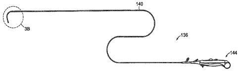
Figures 3A, 3B and 3C show a steerable medical instrument 136 of applicants'
invention
in the form of a multidirectional sphincterotome, in which the end effector is
customized for a
sphincter cutting operation. It will be appreciated that the following
description of the
sphincterotome may be readily adapted to steerable medical instruments having
other types of
customized end effectors, including but not limited to ERCP cannulas, stone
balloon catheters,
balloon dilatation catheters, and endoscopic graspers, baskets, snares,
specimen retrieval devices,
or a wound closure devices.
In Figures 3A-3C, the instrument includes an end effector 100, a shaft 140,
and a control
handle 144. The shaft 140 can be a flexible shaft or a rigid shaft, depending
upon the application
for it is designed. The shaft may be made of any material suitable for medical
use, for example,
polyetheretherketone (PEEK), polytetrafluoroethylene (PTFE), fluorinated
ethylene propylene
copolymer (FEP), urethanes, or polyether block amid (PEBA), stainless steel,
polycarbonates
and acrylonitrile butadiene styrene (ABS). PEBA is preferred because of its
lubricity.
Depending upon the application for which the instrument is designed, the shaft
and end effector
will have one or more lumens, shaped and sized for a given purpose. For
example, in a
sphincterotome, the shaft may have a guide wire lumen, a lumen for contrast
medium, lumens to
house the steering control wires, balance lumens, and a cutting wire lumen.
As shown in Figure 3C, the end effector has a region 121 where the stress and
strain of
bending moments is distributed along the length of the region. Hinge elements
may be
distributed along the length of a flex beam 145, which is incorporated into
the end effector. The
hinge elements are optimally engineered to distribute stress over the length
of the beam.
Generally there are more hinge elements in the plane where there will be the
greatest freedom of
movement (e.g., in the cutting plane of a sphincterotome). The spacing between
the hinge
elements can be varied along any bending plane. In general, a hinge element
may take the form
of a groove, a slot, a spiral slot (screw thread fonn), or any other
structural element that functions
as a hinge.
In general, the end effector can be manufactured by injection molding.
Alternatively,
hinge elements can be laser cut into an end effector (e.g., into a Nitinol
beam incorporated into
an end effector). In yet another embodiment, hinge elements can be machined
into the end
effector.
CA 02652089 2008-11-12
WO 2007/136829 PCT/US2007/012067
Figure 3B shows a portion of the shaft 140 and the end effector 100 of the
steerable
medical instrument 136 of Figure 3A. In this embodiment, the end effector
includes a molded
flex tube (referenced in FIG. 3C as. 145), an insulated cutting wire 109 and a
distal tip 108. The
end effector 100 is manufactured and engineered first as a separate component
from the shaft
5 140. Later in the manufacturing process, the end effector and shaft are
fixedly attached at 143.
In a preferred embodiment, a sleeve is disposed at the lap joint between the
end effector and
shaft to prevent the leakage of contrast fluid and to join the end effector to
the shaft. In contrast
to prior art designs in which the entire instrument is formed from a single
extrusion, applicants'
two-component design allows for precise tip control.
10 Each of the steering control wires in the shaft and/or end effector may be
housed in a
thin-walled PTFE tubing sleeve 146 to reduce friction and to help provide
precise tip control. In
addition, the flex tube may be covered in whole or in part with an elastomeric
sleeve 147 made
of urethane, silicone, styrene-ethylene-butylene-styrene (SEBS), or
thermoplastic elastomer
(TPE). The sleeve functions to keep contrast media from leaking from the end
effector, and has
the additional advantage of generating a composite material, which helps the
flex tube to resist
kinking and bending forces while the elastomeric sleeve allows for
flexibility.
The shaft 140 may include one or more elements (such as a wires, fibers or
slugs of
metal, polymer or glass) having a higher modulus than the modulus of the shaft
to transmit
control forces in the instrument. Figures 3B and 3C illustrate a preferred
embodiment in which
two metal stiffening wires 142A and 142B are co-extruded in the shaft 140. The
co-extruded
stiffening wires 142A and 142B can be made of stainless steel, carbon fiber,
PEEK,
polycarbonate, ABS; or glass fiber. In some embodiments, the co-extruded
stiffening wires
terminate prior to the pre-curve of the shaft 148 (as shown below in Figures
3B and 3C). In
other embodiments, the co-extruded stiffening wires extend through the pre-
curve. It may be
desirable to extend the co-extruded stiffening wires through the pre-curve if
the steering control
wires are made of a monofilament or braided wires.
In some embodiments (not illustrated here), ink may be applied to or
incorporated in the
shaft to indicate to the operator where the cutting wire 109 exits the shaft.
The ink can be a
marker made out of Teflon.
Figure 3C shows the end effector 100 connected to the distal end of the shaft
140,
according to an illustrative embodiment. The shaft 140 can be a flexible shaft
where the distal
end can include a pre-curve 148 mechanically formed in the shaft. The function
of the pre-curve
CA 02652089 2008-11-12
WO 2007/136829 PCT/US2007/012067
11
148 is to optimize the orientation of the end effector as it emerges from the
exit port of the
viewing scope. In a preferred embodiment, the internal wires running through
the desired pre-
curve section of the shaft are rolled over a mandrel to obtain a curved shape.
In the embodiment
of Figure 3C, the intemal wires forming the pre-curve (specifically, the
cutting wire and steering
control wires) are not shown. It is also possible to use the co-extruded
stiffening wires in the
pre-curve section. When the instrument is advanced through the working channel
of an
endoscope, the mechanical pre-curve must flatten out so that the instrument
can be advanced
through the channel. Accordingly, the wires forming the pre-curve 148 must
have sufficient
motion capability to allow the instrument to flex into a straight position
during insertion and
passage through the endoscope. When the instrument emerges from the scope's
exit port, the
internal wires within the instrument spring back to their original pre-curve
formation. The use of
a mechanically formed precurve 148 has advantages over prior art pre-curves
formed by heat
treating the catheter shaft.
In general, the pre-curve 148 forms an approximately 45 to 90 bend in the
instrument.
The bend radius of the pre-curve should be tighter than the bend radius of the
channel from
which the instrument is delivered (e.g., the bend radius of the working
channel in an endoscope).
Preferably, the bend radius of the pre-curve is less than about 1 inch.
In Figure 4A, the flex tube 150 of the end effector has a plurality of hinge
elements in the
form of notches 149 made in the wall of the flex tube material. The flex tube
in this illustrated
embodiment is a laser cut Nitinol flex tube. Alternative flex tubes in this or
any of the
embodiments described herein may be made of polypropylene, polyethylene,
polyetherimide
(PEI), polycarbonate, polyethylene terephthalate (PET), PEEK, or a nylon
material. A steering
control wire 152 extends through the flex tube 150. More than one steering
wire may be present
in the end effector depending upon how many planes of motion are desired in
the instrument.
Bands of heat-shrink material 156 (such as PET) are disposed at predetermined
locations along
the flex tube 150. In addition to the traditional role of providing distance
markers along the
cutting wire 109, the heat-shrink bands may be employed to maintain and hold
the position of the
steering control wires within the end effector. The flex tube 150 can be
encased by a sleeve 160
to seal in contrast fluid. In a preferred embodiment, the flex tube 150 is
made of polypropylene
and the flex sleeve 160 is made of urethane.
Figures 3A-3C and Figure 4A illustrate embodiments of Applicants' steerable
instrument
that comprise a cutting wire 109. In addition to the steering control wires
152, the cutting wire
CA 02652089 2008-11-12
WO 2007/136829 PCT/US2007/012067
12
109 may be used for steering the instrument in the cutting plane. In these
embodiments, the
cutting wire 109 extends from the user handle 144 distally through the shaft
140 to a point near
or within the end effector 100, at which point the cutting wire exits the
inside of the shaft 140
through a sidewall port and runs distally along the outside of end effector to
a point proximal to
the tip 108 of the end effector 100, at which point the bowing wire 109 enters
another sidewall
port (as illustrated in Figure 4B) and is anchored inside the end effector
100. In some
embodiments, the cutting wire exits at the proximal end of the end effector.
Tension applied to
the cutting wire 109 pulls the cutting wire taut and causes the distal end 108
of the end effector
100 to flex in the direction of the applied tension. In Applicants' invention,
the end effector can
flex from 0 to about 180 in the primary plane of bending (e.g., the cutting
plane), and
preferably from about 80 to about 110 . In other embodiments, the instrument
may have a left
steering control wire and a right steering control wire in addition to the
main bowing or cutting
wire. Tension applied to the left steering control wire causes the distal end
108 of the end
effector to bend left. Tension applied to the right steering control wire
causes the distal end 108
of the end effector 100 to bend right. Left and right steering control wires,
in Applicants'
invention, may create up to about 90 of motion from the primary plane of
bending, and
preferably from about t 25 to about +- 45 . In alternative embodiments, the
steerable instrument
may have four steering control wires (up, down, left and right), but no
cutting wire.
In some embodiments, the tip 108 of the end effector is a rigid tip attached
at the distal
end of the flex tube 150. The tip 108 can have a smooth, rounded geometry that
facilitates
atraumatic cannulation. In some embodiments, two lumens can eicit the tip 108,
namely a guide
wire lumen and a second lumen for contrast media injection. Altematively, the
tip 108 can
contain a single common exit port for both the guide wire and the contrast
media. The tip 108
can be manufactured using any recognized technique suitable for medical devise
manufacturing,
including injection molding.
As in Figure 4A, the flex tube 150 of the end effector is located in a region
proximal to
the tip 108 of the end effector. An eccentric load can be applied to the one
or more control wires
152 to articulate the end effector out of the plane of the cutting wire 109.
The material
characteristics of the flex tube 150 can prevent the end effector 100 from
buckling or kinking
under this stress. The flex tube 150 can be coated with an electrical
insulating material, such as
Parylene C, a di-para-xylene-based polymer coating provided by Parylene
Coating Services, Inc.
of Katy, Texas, Teflon, TetraFluorEthylene-Perfluorpropylene (FEP),
Polytetrafluoroethylene
(PTFE), or Polyimide. In some embodiments, the insulated flex tube is further
encased in a
CA 02652089 2008-11-12
WO 2007/136829 PCT/US2007/012067
13
sleeve of flexible material 160 to provide a smooth exterior surface. The
sleeve 160 may be
formed from silicones, urethanes, styrene-based copolymers such as styrene-
ethylene-styrene
block copolymer (SES), and thermoplastic elastomers such as KratonTM, PebaxTM,
and
SanopreneTM.
In some embodiments, a flex tube may be formed by making a spiral cut into the
distal
end of the shaft of the biliary catheter.
Figure 4B shows one embodiment for attaching the flex tube 150 to the tip 108
of the end
effector 100. The flex tube 150 can be recessed concentrically inside the tip
108, with the
flexible sleeve 160 abutting the tip 108. Adhesives or heat shrink can be
applied at the lap joint
164. In some embodiments, the surface of the shaft 140 and the end effector
100 are treated
prior to adhering or attaching the shaft to the end effector 100. The surface
can be treated using
etching, plasma or corrona. The proximal end of the flex section can be joined
to the distal end
of the shaft 140 in a similar fashion.
Figure 4C shows a steering control wire 152 running through the flex tube 150
according
to an illustrative embodiment. In the case of a sphincterome, with the cutting
wire 109 located in
the 12 o'clock position, the steering control wires 152 can be located
anywhere between the 12
o'clock to 6 o'clock range, and the 6 o'clock to 12 o'clock range,
respectively. In some
embodiments, the control wires 152 are placed at about 110-120 radially on
either side of the
bowing wire 109. Adhesive can be used to bond the cutting 109 and steering
control wires 152
into the tip 108 of the end effector 100. In some embodiments without a
cutting wire, there are
four steering control wires at 3 o'clock position, 6 o'clock position, 9
o'clock position, and 12
o'clock position.
Figure 4D shows the different elements of an end effector 100. A plurality of
heat shrink
bands 156 can be employed around the flex tube 150 to create "eyelets," which
can maintain the
control wires 152 in proper alignment in the flex tube 150. Alternatively, a
single piece of heat
shrink can be spiral cut and employed around the flex tube 150 to secure the
control wires 152 in
proper alignment. In some embodiments, the tip 108 is provided with a
hydrophilic coating to
ease cannulation. A sleeve 160 can be used to seal contrast fluid in the end
effector. The sleeve
160 can be made of urethane.
Figure 5A shows the hinge elements in a flex tube 169 of an end effector
according to
another illustrative embodiment. The hinge elements in the flex tube 169 can
be disposed at
CA 02652089 2008-11-12
WO 2007/136829 PCT/US2007/012067
14
different points along the longitudinal axis of the end effector to change a
material property such
as stiffness. In this embodiment, the hinge elements are "T-bar" notches 173.
T-Bar shaped
notches 173 can reduce stress concentrations and improve flexing fatigue. In
some
embodiments, the flex tube 169 is injected molded to generate a varying
pattern of notches to
change the stiffness of the flex tube 169 along its longitudinal axis. In some
embodiments, the
end effector has a region where the stress and strain of bending moments is
distributed along the
length of the region. In this embodiment, the spaces between the T-bar notches
are larger at the
proximal end of the end effector and taper down to become smaller and smaller
as one nears the
distal tip. The orientation, disposal and spacing of the hinge elements can be
varied along any
bending plane.
In some embodiments, the end effector can experience a greater bending moment
at the
proximal end of the end effector and a lesser bending moment at the distal end
during use.
Generally there are more hinge elements in the plane where there will be the
greatest freedom of
movement (e.g., in the cutting plane of a sphincterotome). The distal end of
the flex tube 169
can have a greater density of hinge elements than the proximal end of the flex
tube 169 to
account for the variable bending moments. In some embodiments, changing the
density of hinge
elements in the flex tube 169 allows greater flexibility at the distal end of
the flex tube 169 and
the end effector while accounting for the increased bending moments
experienced at the
proximal end. By increasing the spacing between the hinge elements at the
proximal end of the
flex tube 169, the proximal end of the flex tube 169 can withstand the greater
bending moments.
The design also has the effect of distributing stress over the length of the
beam instead of
concentrating the stress and strain which can lead to kinking and compromise
the structural
integrity of the end effector. In some embodiments, notches can be placed
perpendicular to one
another. For example, in Figure 5A, notches 172 are disposed perpendicular to
T-bar notches
173. This configuration can account for bending moments and distribute strains
and stresses
experienced in the end effector in multiple planes. A plurality of notches can
be disposed at
different angles relative to one another to account for bending moments in
multiple planes. The
notches can generate a more even distribution of stresses and strains in
multiple planes.
Figure SB shows an alternative pattem of hinge elements, wherein T-Bar notches
173 are
used in the distal end of a flex tube but are not used in the proximal end.
Figure 5C shows yet another pattern of hinge elements that can be used in a
flex tube. In
this embodiment, the spacing between the notches 176A to 176E perpendicular to
the
CA 02652089 2008-11-12
WO 2007/136829 PCT/US2007/012067
longitudinal axis of the flex tube are varied to account for the changing
bending moments in the
flex tube 169. In this embodiment, the spacing decreases as one moves in the
distal direction.
Varying the spacing between the T-Bar shaped notches can vary the stiffness of
the molded
flextube along its longitudinal axis. T-Bar shaped notches can be useful if
the flextube is made
5 of Nitinol, to account for the brittle nature.
Figure 6A shows a molded flextube 177 according to another illustrative
embodiment. In
some embodiments, the end effector is not a flex tube attached to a separate
tip 108, but is
instead an integrally molded flextube 177. The molded flextube 177 can be
injection molded to
have notches 178 variably disposed along its length to account for bending
moments. Simple
10 notch geometry, as shown here, may be acceptable for semi-rigid plastic.
In the illustrated some embodiments of Figures 6A and 6B, the distal end of
the molded
flextube forms a fluted tip 181. The fluted tip can reduce the frontal area of
the tip and reduce
trauma. In some embodiments, the fluted tip 181 reduces the force required to
enter the
sphincter. The fluted tip 181 can be molded in one piece with the flex tube,
or may be separately
15 made and attached.
As illustrated in Figure 6B, the molded flextube may include a steering
control wire
channel 182 in the flextube to provide support and maintain control wire
positioning during
flexing. The molded flextube can also have a concentric element 183 that
protrudes out and acts
as an interface with another device. Guides 180 are provided in order to
prevent displacement of
the steering control wires. The hole 184 in the proximal end of the end
effector can mate with a
hole drilled in the distal end of the shaft, for joining the two parts. A
mandrel may then be
inserted through the assembly and glue can be injected to join the end
effector, the mandrel
preventing glue from encasing the lumen.
Figure 11A shows an alternative end effector comprising a flexible spring
region 344 and
a distal end cap 348. A cutting wire and two steering control wires (352 and
353, respectively)
run through the shaft 140, exit the shaft and run outside the end effector
over the spring region,
reenter the instrument at a point near the distal tip, and are anchored inside
at or near the distal
tip. To reinforce the device under cutting wire tensioning loads, the end
effector utilizes a simple
compression spring 356 and an end cap 348. The end cap 348 can be made of
metal or plastic.
The left and right tensioning wires can be covered with a material that can
prevent tearing or
abrasions during insertion of the device and bowing of the bowing wire. A
silicone covering
material may be bonded onto the endcap 348. Judiciously spaced wire guides may
be disposed
CA 02652089 2008-11-12
WO 2007/136829 PCT/US2007/012067
16
along the axis of the spring 356 to prevent the steering control wires from
passing the center of
the compression spring 356 during loading. The lumen 360 is stiffened with a
metallic based
oversheath to reduce lumen compression during loading. The compression spring
356 may
comprise one continuous spring or spring segments. Intermediate wire guide
spacers can be used
along the length of a continuous spring or at the ends of spring segments that
can allow the range
of flexibility for the device to reach beyond the -45 -0 -+45 range.
Figure 11B illustrates yet another embodiment of an end effector, here applied
to a
sphincterotome. The instrument comprises two control steering wires (left and
right,
respectively) 364 and a third wire, which is the bowing or cutting wire 368.
The three wires can
extend from a point of attachment in the control handle of the device to a
point near or at the
distal end of the device. Preferably, the three wires can be spaced around the
longitudinal axis of
the catheter at 1200 intervals. The device can also include a concentric guide
wire lumen 372
located on the longitudinal axis of the catheter. The guide wire lumen can
also be used to deliver
contrast media. Alternatively, the surgical instrument can include a separate
contrast media
lumen. The left and right steering control wires may be anchored in the distal
end of the device
by wrapping the wires around the outer wall of the guide wire lumen as shown
at 376. The distal
end of the cutting wire 368 is formed into an integral compression spring. In
this design, the
distal end of the integral spring component has an end moment load exerted on
it which cases a
curvature. The deflection capabilities of the integral spring component enable
the distal tip of
the end effector to handle very tight curvatures without permanently deforming
the material.
The compression spring structure allows multi-directional displacement and
compressive
rigidity. Because the bending stiffness in the spring configuration is lower
than the bend
stiffness in conventional sphincterotomes, wherein the cutting wire is
anchored at the distal tip
by way of a rigid connection, the integral spring effector reduces the forces
required to actuate
the tip. Furthermore, the integral bowing wire 368 and spring tip construction
eliminates a
number of components and assembly steps such as welding, crimping and bonding
in a small
area. The coil spring 380 can provide the catheter with a high degree of kink
resistance. The
integral spring can keep the catheter body in circular form, even if localized
intercoil wall
kinking might occur, so that the guide wire can pass through the guide wire
lumen 372 in a tight
bend. The tensioning wire wrapped anchor 376 has a lower profile and is less
costly to
manufacture than existing T-tube wire anchor techniques. Conventional devices
utilize a T-
anchor that is crimped, welded and inserted into the distal end of the bowing
wire lumen. This
design is costly, space-consuming, and tedious to assemble.
CA 02652089 2008-11-12
WO 2007/136829 PCT/US2007/012067
17
As shown in Figure 11C, the spring and left-right tension wires 364 can be
covered at the
distal end of the device by an electrical insulating material 384, such as a
silicone elastomer.
The insulating material 384 can protect "the adjacent tissue and to keep the
tension wires 364 near
the spring wires, particularly in severe bend conditions when the wires may
pass the centerline of
the spring. The elastomeric insulating material 384 can function to keep the
wires in the correct
position, and can deflect enough so that sliding motion between the wires and
elastomer surface
is not required.
In some embodiments, tip of the device is a hard PTFE tip, for example by
using a
conventional catheter tipping process. The spring can be covered with an
elastomer or other
insulating material 384 for electrical insulation. In another alternative
embodiment, a convoluted
PTFE shrink tube is placed over the spring coils for friction resistance and
electrical insulation.
In some embodiments, silicon elastomer is placed over the spring coils. The
convolutions allow
the shrink tube to flex with only a moderate effect on the actuation loads and
tip rigidity.
Integral molded silicone insulation 384 can be less traumatic than a hard PTFE
shaft tip cut at a
right angle.
The use of insulation elastomer 384 at the distal tip can provide for a high
voltage yet low
mechanical stiffness insulation method. Using a small diameter PTFE section
along with a linear
spring can prevent the shaft from kinking and provides a catheter with more
repeatable arcing
motion from the tip.
In some embodiments, the left-right tensioning wires 364 are overmolded
adjacent to the
integral flex spring 380. This construction allows the wires to move
moderately relative to the
coil springs. During the tensioning action, the wires tend to move away from
the coil spring,
increasing the moment arm and effectively decreasing the applied load for a
given angular
deflection and preventing "neutral axis wire crossover." In some embodiments,
the wires do not
cross the neutral flex axis of the system, allowing the opposite tensioning
wire to bring a
deflected tip back to a neutral position.
A device having a spring tip 384 end effector may be manufactured by, for
example,
cutting the catheter shaft to length, reducing the tip diameter using
conventional heated, drawn-
down dies and core pins, and trimming back the length of the reduced tip. The
bowing wire 368
and guide wire lumens 372 can be skived. The injection lumen can be skived
over to the guide
wire lumen 372. In some embodiments, the bowing wire 386 is fed into its
respective lumen.
The bowing wire 368 tip can be formed into a compression spring 380 using a
bench top spring
CA 02652089 2008-11-12
WO 2007/136829 PCT/US2007/012067
18
winder. The spring can be assembled over the reduced diameter tip. The left-
right tensioning
wire 364 can be cut to length and the loop ends are fed into the tensioning
wire lumens in the
catheter shaft. The end of the left-right pull wire can be formed into a
retaining loop 376 using a
device similar to a bench top spring winder. The formed left-right wire anchor
can be assembled
onto the distal end. The tip can be overmolded with, for example, an
insulation elastomer 384
such as silicone elastomer, and flexed. The distal tip 388 can also be formed
from, for example,
PTFE from the catheter extrusion itself, to provide a hard, atraumatic surface
for cannulation.
Figure 12A shows a flex beam end effector 392, according to an illustrative
embodiment
wherein the end effector comprises a Nitinol flex beam 396 and an elastomer
overmolded flex
section 400. A Nitinol flex beam 396 can utilize its super-elastic portion of
the stress strain
curve to allow flexure and still return to a nominal center position. In some
embodiments, the
flex beam end effector 392 has control wires 404 and a bowing or cutting wire
408.
A flex beam 396 made of Nitinol can achieve an extremely tight radius of
curvature
without failure. Nitinol material in the appropriate heat treatment and alloy
can exceed the
elastic strain limitations of ordinary steels and metallic materials, allowing
for greater deflection
than would normally be possible. The actuation forces are substantially lower
with a Nitinol flex
beam operating in the super-elastic region. Lower actuation forces tend to
decrease control
system losses and allow for a more sensitive control feel. The flex beam 396
can achieve an
extremely tight radius without failure. In the super-elastic region, the
stress strain curve of
Nitinol is essentially flat from 1% strain to 8% strain, which can translate
into high tip
deflections with no additional motion resistance.
In some embodiments, the flex beam end effector 392 has a continuous guide
wire lumen
398, which provides for a burr-free guide wire path. This can reduce the drag
of the guide wire
from burrs and sharp edges, thereby facilitating the cannulation process.
During the cannulation
process, the user can "feel" when the guide wire touches tissue. Additional
resistance or burrs
can cause a "mis-read" of the guide wire/tissue contact.
The small, frontal cross-section and overall low profile of the flex beam end
effector 392
reduces the required cannulation forces, particularly if a user attempts to
cannulate a "tight"
papilla. In some embodiments, the surgical instrument is a biliary catheter,
including a flex
beam 396 that provides an improved cannulation process that minimizes the
number of
unsuccessful cannulation attempts, which are well-known for causing
pancreatitis.
CA 02652089 2008-11-12
WO 2007/136829 PCT/US2007/012067
19
Manufacture of the flex beam end effector 396 can require little wire forming.
In some
embodiments, a catheter extrusion 397 is cut to length, a counter-bore is made
on the guide wire
axis. A center guide wire lumen can be cut and skived to allow contrast
passage at a cross-over
hole 424.
As shown in Figure 12B, the bowing wire 408 can be attached to the flex beam
396 using
a cylindrical crimp tube 395. The tip of the end effector 412 can be
overmolded with a polymer.
A Nitinol flexbeam wire can be crimped to the bowing wire and steering control
wires 404 at the
distal end of the flex beam end effector 392. The tip 412 can be overmolded
with a hard polymer
to capture the wires and flexible tube 396 in their correct orientation. The
stationary end of the
flex beam 396 and tube 397 can be mounted into a shaft 428 using either a
force fit and/or by
bonding. The tube 397 can be used to unite the overmolded components. The
steering control
wires 404, flex beam 396, and tube 397 can be overmolded with a silicone
elastomer 413 for
insulation. The control wires 404 can be threaded through the shaft extrusion,
and adhesive is
applied to connect the tip assembly. A slit can be cut in the extrusion and
the bowing wire 408 is
fed through the opening of the catheter to complete the tip assembly.
Figures 13A and 13B together illustrate an integral spinal tip end effector
444. The
integral spinal tip 436 can include a plurality of hinge elements in the form
of spinal flextures
440, which allow bending along their "weak" axes, yet are stiff in
compression. This
configuration allows moment loads to be easily generated with small pull wire
motions. The
spinal tip 436 can be a single core component, which can be manufactured, for
example by
injection molding. In some embodiments, the wire anchoring method is
simplified with no
welding, bonding or critical processes. The overmolded, atraumatic tip may be
added, and can
achieve support from the underlying integral spinal structure. In this
embodiment, as well as the
other various embodiments described herein, separate guide wire and contrast
media passages
can merge proximal to the tip of the end effector. This allows the guide wire
to stay substantially
free of contrast media. When certain contrast solutions, for example those
that are barium-based,
flow along the length of the guide wire lumen, the solution can cause the
guide wire to have a
`gritty feel', thereby de-sensitizing the cannulation process for the user. In
some embodiments,
the merger of the guide wire lumen 460 and contrast passages is accomplished
on the proximal
side of the flexible section 456 of the catheter so that the tip size can be
reduced. In some
embodiments, the passages merge into a single lumen at the distal end of the
shaft. Cannulation
can be easier to accomplish with a smaller sized catheter tip.
CA 02652089 2008-11-12
WO 2007/136829 PCT/US2007/012067
The integral spinal tip end effector can be manufactured through a series of
steps. The
catheter shaft 456 can be cut to length. A spinal tip 436 can be inserted into
the guide wire
lumen 460. The material for the molded spinal tip 436 can be, for example, a
high temperature
material such as FEP. The tip assembly can be overmolded. In some embodiments,
PTFE is
5 preferred around the bowing anchor and extrusion exit skive locations. The
bowing wire 464
and left-right pull wire loop 468 can be inserted into their respective
lumens. As shown in
Figure 13B, the distal end of the bowing wire 464 can be wrapped around the
tip and looped
around itself. The left-right pull wire 468 can be wrapped around the end of
the tip.
As shown in Figure 13C, the flexible portion 436 of the tip of the end
effector 444 may
10 be overmolded with an elastomeric materia1472. The tip of the end effector
444 can be
overmolded using silicone, SEBS, urethane, or other materials suitable for the
flex sleeve of the
end effector. The inside of the tip can be relieved to allow passage of a
guide wire. The integral
spinal tip 436 allows for flexibility in two planes and stiffness in
compression, which results in a
more sensitive device because the tip is not deflected axially (higher axial
spring rate). This can
15 be an advantage during cannulation where manual dexterity and "feel" is
important.
The injection lumen overmolding core can be inserted into the injection lumen.
The
guide wire lumen core can be inserted into the end effector. The end effector
can be overmolded
472 and the cores can be removed and tip flexed. In some embodiments, the pull
wires 468 are
some distance from the underlying structure and can remain attached to the
elastomer 472, yet
20 deflect the far field elastomer 472 to achieve their function. This can
simplify the overmolding
process and eliminates a number of complex coring operations.
Figure 14 shows a segmented end effector 480 according to an illustrative
embodiment.
A segmented end effector 480 can include segments 484 A-J in the distal
section. In some
embodiments, the segments are about 0.1 of an inch long. The segments can be
molded from
plastic with discrete lumens for the guide wire, tensioning wires, bowing or
cutting wire and
optionally contrast media. In some embodiments, the guide wire lumen is lined
with a polyimide
material that improves the alignment of the segments 481 and provides a
channel for distal dye
injection. This embodiment provides for a flexible distal section. The
segmented portions of the
end effector 480 can be molded, machined or extruded by known methods.
In yet another alternative embodiment, the end effector comprises a tapered
beam, where
the diameter of the beam is larger at its proximal end and tapers to a smaller
diameter as one
approaches the distal end of the beam. The beam is designed to be thicker at
the proximal end
CA 02652089 2008-11-12
WO 2007/136829 PCT/US2007/012067
21
because this is where the beam experiences a higher bending moment. This
design is feasible for
simple embodiments of applicants' medical instrument that do not require many
lumens and
wires to be located in the end effector.
Figure 7 shows a plurality of lumens in a shaft 140, according to an
illustrative
embodiment. The multi-lumen shaft can be made out of TeflonTM. In this
embodiment, the shaft
has a guide wire lumen 185, a dedicated contrast media lumen 188, first and
second steering wire
lumens 192 and 193, and a cutting wire or third steering control wire lumen
196. In a preferred
embodiment, the bowing wire lumen 196 is in the 12 o'clock position, the
steering wire lumens
192 and 193 are positioned at approximately the 4 and 8 o'clock positions, the
contrast lumen
188 is opposite lumen 196, and the guide wire lumen 185 is in the center. As
illustrated in
Figure 7, the shaft may further include two stiffening wire lumens 200 at the
3 and 9 o'clock
positions. The stiffening wires aid the shaft 140 in transmitting motion from
the control handle
of the device to the tip 108 of the end effector 100 and can allow the user to
maintain precise
control. Orienting the stiffening wires in the 3 and 9 o'clock positions
predisposes the device to
bend in the 6 and 12 o'clock positions, which enables the operator to better
control the tip
orientation as the device exits the scope. The ability to control end effector
orientation out of the
scope can facilitate easier cannulation. Stiffening wires also can prevent
spiraling of the shaft
during extrusion. Finally, as illustrated in Figure 7, the shaft 140 may
include balancing lumens
204. The balancing lumens 204 can be used to achieve pressure stabilization of
the shaft 140
generated by the other lumens.
In some embodiments of applicants' steerable medical instrument, it will be
desireable to
merge the separate guide wire and contrast media lumens into a single lumen at
a point proximal
to the distal end of the instrument. To accomplish this, the internal wall
between the guide wire
lumen 185 and the contrast lumen 188 can be cut away so that the two lumens
merge and
contrast media enters the guide wire lumen 185 and exits at the tip of the end
effector. The
merged guide wire/contrast lumen can run over a distal 20-25 mm of the
instrument, minimizing
the disruptions on the surface of the tip of the end effector. This
configuration allows for a
single edge created on the central axis of the device by the merged guide
wire/contrast lumen
exiting the distal most end of the tip of the end effector. In some
embodiments, the configuration
of merging the guide wire/contrast lumen enhances hydrostatic device
exchanges.
In some embodiments, a stylet is used in the guide wire lumen 185 of the shaft
140 to fill
in the distal exit port, to generate a smooth, continuous, edge-free surface
at the tip to ease
CA 02652089 2008-11-12
WO 2007/136829 PCT/US2007/012067
22
cannulation. In one embodiment, a polymer stylet is employed. In another
embodiment, a pre-
loaded guide wire is indexed like the stylet for initial cannulation. In yet
another embodiment, a
needle knife stylet is employed.
Figure 8A shows a prior art control handle 208 with a rotatable thumb loop 212
to steer
the surgical instrument and a bowing control element 216 to control a bowing
or cutting wire
109. The control handle 208 also includes an electrode connector 220, a
contrast port 224 to
inject contrast media, and a guide wire port 228. There is a shaft 140
connected to the control
handle 208 and the shaft is shown in a bowed configuration.
Figure 8B shows a control handle assembly according to an illustrative
embodiment of
Applicants' invention. The control handle 232 has an anatomically shaped
handle including a
multi-directional control 236 in the form of a rounded wheel. Rotating the
multi-directional
control 236 to the operator's right moves the tip 108 of the end effector 100
of the device to the
right. Rotating the multi-directional control 236 to the operator's left moves
the tip 108 of the
end effector 100 to the left. As illustrated in Figure 8B, the control handle
232 assembly can
also include a bowing/cutting control 240 that can be in the form of a rounded
wheel. Rotating
the bowing/cutting wheel 240 in the proximal direction tensions the
bowing/cutting wire 109 and
causes the device to bow in the cutting plane. In some embodiments, the multi-
directional
control 236 and the bowing/cutting wheel 240 are coated to increase traction
during use.
The control handle assembly can also include a finger ring 244 at the proximal
end of the
handle assembly. The finger ring can provide an anchor or point for grounding
the device in the
operator's hand.
The control handle 232 can also include a braking control device 248. In one
embodiment, the braking control 248 is in the form of a push-down button,
which may be tumed
on or off as the operator desires. If the operator activates the braking
control 248 by pushing
down on the button, the operator can then actuate the bowing control wire 109
and the end
effector 100 will stay in the position where it is placed. Altematively, the
braking control feature
can be a constant control that is always tumed on. In some embodiments, the
handle can have a
friction control pad to activate and deactivate braking control.
Figure 8C shows an alternative embodiment of a control handle 252. As in this
embodiment, the finger ring 244 can be placed under the control handle and the
contrast port 224
can be located under the control handle.
CA 02652089 2008-11-12
WO 2007/136829 PCT/US2007/012067
23
Figure 8D shows an altemative control handle 256 where the multi-directional
control
236 device is located at the proximal end of the control handle. In some
embodiments, the multi-
directional control device is a joystick that can be manipulated by the user
to split the wire
tension of the control wires. The handle assembly can include a sliding part,
which may be
manipulated to apply tension to the bowing wire 109. In some embodiments, an
elevator of the
endoscope is used to give the unit approximately I 10 of elevation.
Figure 9A shows how foam pads 257 can interact with a control surface of the
multi-
directional control device 236 for "braking" of the instrument. The foam pads
257 can exert a
frictional force on the multi-directional control device 236. In some
embodiments, the frictional
force exerted by the foam pads 257 "brakes" or restrains movement of the
device unless a
rotational force is exerted by the user on the multi-directional control
device 236. In some
embodiments, the foam pads 257 are made of a silicon-based or urethane-based
foam. The foam
pad can be an open cell foam or a closed cell foam. In some embodiments, the
foam is made of a
low compression set foam that does not take a set over time.
In some embodiments, a series of gears 258 and 259 can be used to control a
bowing
wire. The gear teeth can be removed 259 to provide a "neutral position" for
bowing wire
control. This can allow the device to be coiled for packaging without
overstressing the tip. The
gear profile "filled" in provides precise bowing limits. This can prevent
users from breaking or
kinking the device by over-actuating the bowing wire 109.
Figure 9B shows how foam pads 257' and 257" can interact with the multi-
directional
control device 236 and a bowing/cutting control device 240, according to
another illustrative
embodiment. The foani pads 257' and 257" can provide braking action on the
handle controls.
This can allow the user to leave the device in a preferred position even when
moving from one
control to another. Unless the user exerts a force on the multi-directional
control device 236 or
the bowing control 240, the device remains in the position. In some
embodiments the control
wire 152 can be a control wire loop instead of separate control wires.
As shown in Figure 9B, the steering control wires 152 can be actuated using a
"drum ring
gear" 260. In some embodiments, when a user exerts a force on the multi-
directional control
236, it actuates a gear 261 that actuates a drum ring gear 260 which
manipulates the steering
control wires 152. The drum ring gear 260 can rotate 180 and works as a
tension control
system. When the drum rotates in a first direction, one steering control wire
tenses and the other
steering control wire relaxes. In some embodiments, roller pins 262 are placed
to guide the
CA 02652089 2008-11-12
WO 2007/136829 PCT/US2007/012067
24
control steering wires from the drum ring gear 260. In some embodiments,
stationary pins are
used.
Figure l0A demonstrates how the steering control wires 152 can be attached to
the
control handle. In this embodiment, the multi-directional control 236 actuates
the control wire
by the use of a bevel gear with a pulley. A user can rotate the multi-
directional control 236 in a
first direction that is connected to a first gear 263 that engages with a
second gear 264. The
second gear can include a pulley 268 that manipulates the control wire 152.
Figure lOB shows the use of a double helix configuration to manipulate a left
control
wire 152' and a right control wire 152". In this illustration, the multi-
directional control 236 is
connected to a helical camshaft 272. The helical camshaft 272 can be connected
to two carriers
276 that actuate control wires 152' and 152". The user can rotate the multi-
directional control
236, which can rotate the helical camshaft 272. The carriers 276 can follow
the tracks 280 in the
helical camshaft 272, manipulating the control wires 152 and 152".
Figure 10C shows a double lead screw used to actuate the control wires 152'
and 152",
according to an illustrative embodiment. The multi-directional control 236 is
connected to a spur
gear 284 that can be connected to two lead screws 288. Carriers 292 that
actuate the control
wires 152 can be attached to the lead screws 288. The user can rotate the
multi-directional
control 236, which can rotate the spur gear 284, causing the lead screws 288
to rotate. The
carriers 292 can move along a longitudinal axis of the lead screws 288
manipulating control
wires 152. In some embodiments, mechanical stops are placed on the shaft and
the mechanism
does not require a break.
Figure 10D shows a beaded chain mechanism, according to an illustrative
embodiment.
The multi-directional control 236 is attached to a sprocket driver that
engages a sprocket 300.
When a user rotates the multi-directional control 236, it can engage the
sprocket 300 that
actuates a beaded chain 304 and control wires 152' and 152" that attach to the
beaded chain 304.
Guide rails 308 can be used to control the beaded chain 304.
Figure 10E shows a bevel gear utilized to manipulate control wires 152' and
152",
according to an illustrative embodiment. Rotating the multi-directional
control 236 can engage a
miter gear 312 and a plurality of spur gears 316 and 317. Movement of a spur
gear 316 can
cause movement to racks 320 that can be attached to control wires 152' and
152". In some
embodiments, mechanical stops can be placed in the rack 320 track.
CA 02652089 2008-11-12
WO 2007/136829 PCT/US2007/012067
Figures 10F-10H show a"half-spur" gear utilized to manipulate control wires
152' and
152", according to an illustrative embodiment wherein some of the teeth of the
gears were
removed. In The control mechanism allows for articulation in a first and
second direction and
also has a neutral/rest position. As shown in Figure 10F, when the half spur
gear 316' is rotated
5 in a first direction, the first control wire 152' can be manipulated in a
first direction while the
second control wire 152" is free to move. As shown in Figure lOG, the
configuration of the half
spur gear 316' allows for a neutral position. Figure 10H shows the half spur
gear 316' rotated in
a second direction, allowing the second control wire 152" to be manipulated in
a second direction
while the first control wire 152' is free to move.
10 Figure 101 shows the use of a face cam mechanism to manipulate control
wires 152' and
152". In this illustration, the multi-directional control 236 is connected to
a face cam 324 with
followers 328 and 328' and follower springs 332 and 332'. In the initial
position (neutral) the
followers 328 and 328' can be aligned above the centerline of the cam 324.
This dimension can
be defined by the required forward linear travel of the control wire 152 to
allow tip motion and
15 cam surface angle. When the cam surface drives one follower 328 back, the
other 328' can
follow forward by a controlled amount and enter the dwell surface 336 on the
face cam. The
system can prevent slack build up resulting from extension of the control
wires 152' and 152".
Figure 15 shows the steps for manufacturing a steerable surgical instrument,
according to
an illustrative embodiment. An internal skive 488 can be performed at a distal
end of a multi-
20 lumen shaft, such as a catheter. The shaft can be marked 492 indicating
where the cutting wire
should exit. The proximal and distal surface of the shaft can be prepped 496
to attach to a
control handle and end effector, respectively. In some embodiments, the
surface is treated using
a plasma, corona, or etching procedure. A counterbore 500 can be used to
create a guide wire
port and contrast port 504. Insulated control steering wires and bowing wires
508 can be
25 integrated with the shaft 512.
The flextube of the end effector can be integrated with the flex section 516
which can be
integrated with the tip sleeve. The tip of the end effector can be coated 520.
The end effector
and flexible tube can then be integrated by the use of adhesives. A pre-curve
then can be
mechanically formed in the shaft 524, by using the internal wires, such as the
bowing wire and
steering control wires. In some embodiments, the pre-curve includes at least
two wires.
The parts of the control handle include the idler gear, a bowing wire knob,
rack and
multi-directional control 528 which can be assembled into a control handle
532. In some
CA 02652089 2008-11-12
WO 2007/136829 PCT/US2007/012067
26
embodiments, the controls of the control handle are coated to increase
traction to help engage the
device with the user's hand. The controls of the control handle can be coated
with a urethane. In
some embodiments, the controls are made of a semi-rigid TPE that is not
coated. The control
handle can be integrated to the shaft which has been integrated with the end
effector. In some
embodiments, the device is sterilized prior to use 536.
A steerable medical instrument, as described above, can be positioned in a
patient's body
with the use of a viewing scope having a distal exit port. The scope can be
navigated through the
patient's anatomy and positioned near or adjacent the desired area in the
patient's body. The
steerable medical instrument can be introduced through the scope and advanced
until the distal
end of the instrument protrudes from the distal exit port of the scope. The
distal end of the
instrument can be steered by tensioning at least one steering control wire.
A steerable medical instrument can also be used to cannulate the Papilla of
Vater in a
patient. A flexible endoscope can be used with a steerable medical instrument
as described
above. The endoscope can be navigated through the patient's anatomy and be
positioned so that
the distal exit port is near or adjacent the Papilla of Vater. The steerable
medical instrument can
be introduced through the endoscope and advanced until the distal end of the
instrument
protrudes from the exit port of the endoscope. The instrument is further
advanced and steered to
enter and cannulate the Papilla, wherein the steering is achieved by
tensioning at least one
steering control wire.
While the invention has been particularly shown and described with reference
to specific
illustrative embodiments, it should be understood that various changes in form
and detail may be
made without departing from the spirit and scope of the invention.