Note: Descriptions are shown in the official language in which they were submitted.
CA 02652199 2009-02-02
HOSE MANAGEMENT SYSTEM FOR SUPPLYING CONDITIONED AIR TO AN
AI RC RAFT
Field of the Invention
[0001] The present invention generally relates to a device and a method for
supplying conditioned air for heating and cooling an aircraft while it is
stationary and
on the ground. More specifically, the present invention extends and retracts a
supply hose from a protective container, while one end of the hose is
stationary and
attached to the source of conditioned air.
Background
[0002] It is generally known to supply commercial aircraft with conditioned
air
for heating and cooling. Typically, conditioned air is supplied to the
aircraft from a
ducting system associated with the telescoping corridor that is a part of the
airport
terminal. The air is delivered from the telescoping corridor to the aircraft
with a
flexible and usually insulated air hose. The hose is typically one hundred
feet in
length or more. When not in use, the hose is stored in a bin under the
terminal.
Occasionally, when time permits, a worker may roll the hose into a roll before
storing
the hose in the bin. Often, an individual leaves the hose bent upon itself in
the bin,
thereby increasing undue wear of the hose and predisposing the hose to kink
when
in use. Kinks are undesirable because they decrease the amount of air
delivered
through the hose. The process of hefting the hose into and out of the bin can
cause
snagging and tearing of the hose, further decreasing delivered air. Lifting
and
moving the hose is ergonomically difficult.
[0003] In addition, while all aircraft have a standard connector, this
connector is not located at the same point on all aircraft. Further, the
telescoping
CA 02652199 2009-02-02
corridor is not always located at the same distance from the aircraft. Some
aircraft
require one hundred feet or more of supply hose for the conditioned air to
reach the
aircraft, while others may only require twenty feet. All one hundred feet of
the supply
hose must be removed from the bin regardless of how much hose is required.
Whenever less than the full length of the hose is required, the hose will
likely be bent
and kinked between the terminal and aircraft. A bent and/or kinked hose
reduces
the airflow to the aircraft when compared to a smoothly routed hose. Reduced
airflow reduces the delivered heating and cooling. In some cases, the aircraft
cannot be adequately heated or cooled using air supplied by the ground
facility
through the bent or kinked hose, and the aircraft may then need to operate its
auxiliary power unit (APU). The APU consumes jet fuel and increases the
airline's
costs.
[0004] In addition, another safety issue is that having more hose than
necessary on the tarmac can cause a tripping hazard and make it more difficult
for
the ground operation crews to safely maneuver their vehicles.
[0005] A need, therefore, was previously recognized for an improved device
and a method for supplying conditioned air for heating and/or cooling a
commercial
aircraft. U.S. Patents 6821201, 6776705, and 6834668 to Bombardi et al. are
directed to this improvement. Bombardi supplies a protective container that
dispenses an appropriate length of hose, and retracts the hose when the hose
is no
longer needed. However, the device disclosed by the Bombardi patents has
several
aspects that can be improved upon to increase reliability, functionality, and
ease-of-
use.
2
, ~ .,~~~,~= ~ CA 02652199 2009-02-02
Summary of the Invention
[0006] In retractable hose device such as described by Bombardi, the power
required by the dispensing and retracting device to reliably do its job varies
with the
length of the hose installed in the device. For example, a long hose, due to
weight
and drag, requires a different fevel of energy to retract it than does a short
hose.
Therefore, according to one aspect of the invention, torque sensing circuitry
that is
adjustable according to the hose installed is provided in the hose retractor.
[0007] The ability to retract a hose also depends upon how pliable it is, and
pliability varies according to temperature. A cold hose is less pliable, and
therefore
harder to compact into its container. Also, a cold hose causes the heated air
being
supplied to the aircraft to arrive in a cold condition, until the mass of the
hose is
warmed by the flowing air. Therefore, according to a further aspect of the
invention,
a heater is included within a hose retractor container, keeping the stored
hose warm,
even during cold weather. Alternatively or additionally, a heat exchanging
element
may be provided to either cool or heat the container.
[0008] The person responsible for deploying and aftaching the hose is often
under time constraints and needs to work efficiently. The person could benefit
from
a remote control, such as one mounted on their belt or work uniform, or one
mounted to the hose connector. Another aspect of the present invention
therefore
features a remote control for controliing the device to extend and retract the
hose,
and to turn the supply of air on and off. The remote further features an auto-
retract
mode, allowing ground crew to walk away to another next task while the
unattended
hose is retuming to the container, increasing efficiency beyond what is
available with
existing systems.
[0009] Additional aspects of the invention that improve upon previous devices
3
CA 02652199 2009-02-02
include a variable speed control, a re-engineered drive mechanism that uses
fewer
motors and allows easier maintenance than that described by Bombardi, an
aviary
(bird) deterrent, increased hose-length capacity, an improved hose, and
improved
removable mounting system for use at the airport facility.
[0010] Although these devices are specifically described in relation to
servicing aircraft, the principles of this invention could also be used in
other
applications where hoses must be stored, extended and retracted. Examples of
such applications include supplying air to utility workers working beneath a
roadway
or in a confined space, and the storing of a sanitary waste dump hose attached
to a
waste tank in a recreational camping vehicle.
[0011] Additional features and advantages of the present invention are
described in, and will be apparent from, the detaiied description of the
presently
preferred embodiments and from the drawings.
Brief Description of the Drawings
[0012] The accompanying drawings, which are incorporated in and constitute
a part of this specification, illustrate embodiments of the invention and,
together with
the general description of the invention given above, and the detailed
description
given below, serve to explain the principles of the invention.
[0013] FIG. 1 is a perspective view illustrating an embodiment of the present
invention. A mounting system is also shown.
[0014] FIG. 1A illustrates the embodiment of Fig. 1 in partial cross-section
with the hose illustrated with phantom lines.
[0015] FIG. 2A illustrates a side elevational cross-section view of a portion
of
the embodiment of FIG. 1 while the hose is beginning to be retracted.
4
CA 02652199 2009-02-02
,=
[0016] FIG. 2B illustrates a side elevational partial cross-section view of a
second portion of the embodiment of FIG. 1.
[0017] FIG. 3 illustrates a cross-sectional view of the portion as in FIG. 2A
after the hose is additionally retracted.
[0018] FIG. 4 illustrates an internal perspective view of the hose outlet
portion
of the embodiment of Fig. 1A.
[0019] FIG. 5 illustrates a cross-sectional view as shown per the numbered
arrows in FIG. 7, with much of the middle cap plate removed for clarity.
[0020] FIG. 6 illustrates a perspective view of one belt drive assembly of
FIG.
4 with a portion of a belt.
[0021] FIG. 7 illustrates a detail cross-sectional view of a portion of FIG.
2B
with details of the belt drive shown.
[0022] FIG. 8 illustrates a detail cross-sectional view of a portion of FIG.
7.
[0023] FIG. 9 illustrates a cross-sectional view of the chain adjuster as
shown
per the numbered arrows in FIG. 5.
[0024] FIG. 10 illustrates a diagrammatic view of a hose of the embodiment in
FIG. 1 A.
[0025] FIG. 11A illustrates a perspective view of an operator using the
embodiment of FIG. 1 to extend a hose.
[0026] FIG. 11 B illustrates a perspective view of an operator using the
embodiment of FIG. 1 to attach a hose to an aircraft.
[0027] FIG. 11 C illustrates a perspective view of an operator using the
embodiment of FIG. 1 to retract a hose.
[0028] FIGS. 12, 13 and 14 are electrical schematics of the control unit
controlling the operation of the embodiment of FIG. 1.
, . . ,w.,,~.- .. : _ . . , . : ~. . ~. . . .. .
CA 02652199 2009-02-02
Detailed Description
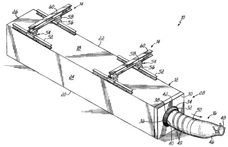
[0029] Figure 1 illustrates a hose management system 10 comprised of a
container 12, a mounting system 14, and an air conduit 16. The container 12
has a
top 18, a bottom 20, a left side 22, a right side 24, an inlet end 26 and an
outlet end
28. For purposes of this description, the direction referred to as forward or
front will
be towards the outlet end 28, and the direction referred to as back or aft
will be
towards the iniet end. A nose cover 30 is on the outlet end. The nose cover
has an
aperture 32 having a perimeter 34. An aviary deterrent 36 is fastened around
the
perimeter of the aperture. The aviary deterrent comprises bristies 38 that
extend
from the perimeter to form an inner aperture 40 through which the air conduit
16
passes. The air conduit comprises a hose 42, a reducer 46, and a coupling 48.
The
hose has an evenly spaced scuff strip 49 and a reflective strip 50. An air
inlet 51
(FIG.2A) is at the inlet end 26 of the container 12. The mounting system 14
comprises a mount beam 52, a mount connector 54 comprised of a lower connector
56 and an upper connector 58, and a top beam 60. The top beam may be provided
as part of the hose management system 10, or it may already be a part of a
facility.
An example of a facility is a telescoping corridor used to load passengers
into an
aircraft. The lower connector 56 connects to the mount beam 52 and the upper
connector 58 connects to the top beam 60.
[0030] With regard to FIG 1A, the hose management system 10 is illustrated
with the container 12 in partial section view and the air conduit 16
represented with
phantom lines. The container 12 comprises a frame 62 covered with a skin 64
(shown partially removed for clarity) of material such as sheet metal. A
middle cap
plate 66 separates a larger rear compartment 70 from a smaller front
compartment
72. The front compartment has a drive assembly 74 having four-belt drives 75
and a
6
CA 02652199 2009-02-02
front cap 76 that is aft of the nose cover 30. A mandrel 78 extends through
the front
cap 76, and the inner aperture 40. An entrapment tube 80 and a support beam 82
are in the rear compartment. In FIG. 1A, the entrapment tube 80 is partially
removed for clarity. The entrapment tube 80 may be one long length, or it may
be
made of shorter sections fastened together. Also illustrated is a control unit
84 that
will be discussed later.
[0031] With regards to FIG. 2A, the inlet end 26 has a rear cap 86 with an
aperture 88 through which conditioned air 90 can fiow as indicated by the
arrow.
Surrounding the aperture is an inner boot 92 and an outer boot 94. The outer
boot
94 connects with a facility air suppiy 96. The inner boot 92 connects with the
hose
42. The hose 42 passes through the entrapment tube 80, which is held to the
rear
cap 86 by entrapment mount brackets 98. A beam adjuster 100 and a beam cap
102 fastens to the support beam 82. The beam cap 102 is on top of the support
beam 82 and has a smooth surface 104 in contact with the hose 42. It is
contemplated that the beam cap 102 could be eliminated, with the use of a
support
beam 82 that provides a smooth surface on which the hose could glide. The
support
beam carries the weight of the hose. The weight varies depending upon the hose
installed, as well as the length of the hose extended or retracted. The beam
adjuster 100 underneath the support beam 82 is used to position the support
beam,
according to the weight of the hose 42 installed. Some hose management systems
may have a hose of maximum length and durability, while others may be ordered
with shorter and lighter hoses.
[0032] FIG. 2A illustrates the hose being retracted by the drive assembly 74
and pushed along the beam cap 102 as indicated by the two solid arrows. As
additional hose is pushed into the entrapment tube 80, the hose compacts while
7
CA 02652199 2009-02-02
maintaining an essentially round cross-section. The entrapment tube has an
outside
surface 108 and an inside surface 110. Perforations 112 in the entrapment tube
allow air within the container to circulate and reach the hose. By heating or
cooling
the air in the container 12, any hose in the container is also heated or
cooled. The
inside surface 110 contacts the hose, creating drag so that the hose will more
closely and uniformly compact along the support beam 82. A further purpose of
the
entrapment tube is to ensure the hose remains straight and unkinked within the
container. The support beam alone, being substantially less in width than the
diameter of the hose 42, may not adequately prevent side to side or upwards
movement of the hose 42 as air flows through it. Such movement may lead to
kinking.
[0033] FIG. 2B is the forward continuation of FIG. 2A. The hose is retracted
into the container across the mandrel 78 and starts to compact in the
entrapment
tube. The hose is retracted into the container until the reflective strip 50
reaches an
optical sensor 116 (FIG. 4) inside the container that signals the control unit
84 to
stop the drive assembly 74. If the hose is of maximum length, it will be fully
compacted (FIG. 3). A hose of a lesser length may be less tightly compacted
than
illustrated.
[0034] The drive assembly 74 will now be further explained with reference to
FIGS. 2B, 4, 5, 6, 7, and 9. A motor 118 mounted on a gearbox 120 fastened to
the
mid cap plate by gearbox mount brackets 122 drives the drive assembly. Power
from the motor is transmitted through a shaft coupler 124 to a main drive
shaft 126.
The main drive shaft is coupled to two secondary drive shafts 128, 130, and
one
manual drive shaft 132 (FIG.5) by a roller chain 134 that passes over a chain
sprocket 136 on each of the four drive shafts (126,128,130,132). The manual
drive
8
CA 02652199 2009-02-02
shaft differs from the secondary drive shafts in that the manual drive shaft
extends
further into the rear compartment and can be accessed through the ieft side of
the
container when a need to manually operate the hose management system arises.
Manually, as used herein, also includes using a powered tool to rotate the
manual
drive shaft. The four shafts 126, 128, 130, 132 are supported on their aft end
by aft
flange bearings 140 on the middle cap plate 66 (FIG. 7). The forward ends of
the
shafts 126, 128, 130, 132 are supported by forward flange bearings 142 on belt
drive bases 144 fastened to the front cap 76. The main drive shaft drives the
secondary and manual drive shafts, so that a driving miter gear 146 on each
shaft
drives a driven miter gear 148. The driven miter gear is on a pulley shaft 150
having
a belt pulley 152 that drives a belt 154 (FIG. 7) on the belt drive 75. The
belt passes
across a small belt support 156, a large belt support 158, and around three
idler
pulleys 160. The belt pulley, idler pulleys, and belt supports are between two
side
plates 162, 164 that are supported by a shaft bearing 168 at a pivot mount 170
that
is mounted to the belt drive. The belt drive base 144 is fastened to the front
cap 76
by fasteners 172. Additionally, the belt drive is held to the front cap by a
shoulder
bolt 174 that passes through a tension spring 176, a slotted hole 178 in the
belt drive
base, and a spring block 180. The spring block is threaded to engage the
threads of
the shoulder bolt. The belt drive, mounted pivotally and pulied by the tension
spring
and the shoulder bolt, applies pressure to the hose. However, the belt drive
is free
to allow irregularities in the hose, or foreign objects the hose may pick up,
to pass
beyond the belt without causing a jam. Additionally, if the shoulder bolt is
removed,
the belt drive may be pivoted away from the hose for additional maintenance
access.
[0035] Inside the hose and not normally visible is the mandrel 78 having four
guide surfaces 184 and three roller tracks 186 and one top roller track 188 in
line
9
. ...... . .. .........,.. ~ , ......... .v, ....,..
,:.e.cu.fYkh?!R2GMMet.ti:;vx.nv.W~+.. _.. . _ .:... . ' . .. . . .. . ~wnY ..
.. _ . ......:.--..r.-.+v.w .... ,:;:
CA 02652199 2009-02-02
with the four belt drives 75. The support beam 82 mounts to the mandrel
underneath the top roller track and extends aft through the entrapment tube.
The
beam cap 102, mounts on top of the support beam aft of the top roller track.
[0036] The drive assembly additionally comprises a chain adjuster 192 best
seen in FIG. 5, and detaiied in FIG. 9. FIG. 5 is a view from the aft of the
middle cap
plate 66, looking forward into the forward compartment. The chain adjuster 192
comprises an adjuster block 194, a tensioner block 196, a rod 198 going
between
the adjuster block and the tensioner block, two nuts 200, an idier sprocket
210, an
idler spacer 212, and a shoulder bolt 214. The tensioner block has two
elongated
holes 216 through which two bolts 218 pass and adjustably fasten the tensioner
block to the mid-cap plate. By adjusting the nuts on the rod, and pushing the
tensioner block away from the adjuster bfock while the two bolts are ioosened,
the
idler sprocket lengthens the path of the roller chain. Then the two bolts are
tightened. This adjustment is performed during chain installation and
maintenance.
[0037] A chain tensioner 220 (FIG. 4) having a stationary block 222, a
pivoting
block 224, an idler sprocket 226, and a spring 228 is fastened to the middle
cap
plate 66. The spring bias pivots the idler sprocket into the chain to
dynamically
maintain tension in the chain.
[0038] FIG. 7 illustrates the positive drive between a tread 229 on the belt
and
the scuff strip 49 on the hose 42. As cogs 230 on the belt pulley contact the
belt
interior 232 and positively move the belt by interfacing with the notches 234,
the
tread 229 interlocks with the scuff strip. The dimensional spacing between the
treads, and the dimensional spacing between the scuff strips are coordinated
so that
a space 238 between the treads will cooperate with the scuff strip. The scuff
strip is
spirally-wound and is therefore not perpendicular to the axis of the hose.
Therefore,
CA 02652199 2009-02-02
a two inch circumferential length of the scuff strip corresponding to the two
inch wide
belt covers slightly more longitudinal length of hose than the width of the
scuff strip.
This longitudinal length is taken into account when calculating the
dimensional
spacing of the tread on the belt. A preferred match is to put the scuff strip,
having a
width of .340 inches at a pitch of 7 inches, while placing the tread at a
pitch of 1.181
inches. The tread is approximately .750 inches wide.
[0039] Stitches 244 securing the flange 246 of the scuff strip to the hose are
shown in FIG. 8. These stitches pass through the entire wall of the hose.
Other
systems for attaching the scuff strip to the hose, or for creating a plurality
of
protrusions either spirally or longitudinally spaced along the hose, are also
within the
scope of this invention. Future protrusions need not be in the form of a scuff
strip.
[0040] Operation of the hose management system is shown in Figures 11A,
11 B, and 11 C. In FIG 11A, an operator using a remote control 248 secured in
the
vicinity of the reducer portion 46 is using the hose management system to feed
out
the hose as he walks toward the aircraft 250. In the event the operator
attempts to
feed out more hose than the hose management system can provide, safeguards are
present and described along with the hose description below. In FIG 11 B, the
operator, having fed out enough hose, attaches the connector to the aircraft.
In FIG
11 C, when the conditioned air is no longer needed at the aircraft the
operator uses
the remote control to send a signal 252 to the hose management system to
retract
the hose into the container. The hose will retract until the reflective strip
50 reaches
the optical sensor 116 inside the container, signaling the hose management
system
to stop retracting. The operator is free to pursue other tasks, and does not
have to
accompany the hose during retraction.
[0041] Alternatively, the remote, rather than being on the hose and uniquely
11
.,~. _
CA 02652199 2009-02-02
programmed to the particular hose management system, may be a multiple purpose
remote 254 (not shown) carried by the operator. Such a remote would use unique
signals to activate the appropriate hose management system among several at
the
airport. Alternatively, the remote may be mated to a single hose management
system, but may include additional controls for other controllable systems in
the gate
area, such as the HVAC system, the HVAC blower, the controls for the motorized
telescoping corridor, lights, and any other controllable or indicator systems
used by
aircraft, flight crews and ground personnel.
[0042] FIG. 10 illustrates a hose configured for use with the hose
management system. The hose comprises a first portion 256 of nominal 14-inch
inside diameter lay-flat hose made of a nyion layer on the inside and a nylon
layer
on the outside with insulation between the two nylon layers. Yellow nylon
iayers are
preferred for visibility. The hose further comprises a second portion 258 of
hose that
need not be insulated. The inside diameter dimension 260 of the hose is
consistent
with the mandrel 78 diameter and the distance across opposing roller tracks
186,
188. An outside diameter dimension 262 of the hose is consistent with the
spacing
between opposing belt drives. The first reflective strip 50 is at a first end
263 of the
hose near a cuff 264 having hook fasteners 266, to which the reducer portion
46
may be attached. Preferably the cuff is eight inches in length and four inches
of it
has hook fasteners.
[0043] A second reflective strip 268 is at a distance 269 from a second end
270 of the hose. In operation, the second reflective strip 268 is sensed by a
second
optical sensor 271 (FIG.4) to stop the drive assembly from feeding out
additional
hose when none remains compacted on the support beam. Distance 269
approximately corresponds to the length of the rear compartment, and is the
12
CA 02652199 2009-02-02
anticipated length necessary to contain hoses to service foreseen aircraft and
airport
combinations. The length and functional diameter of a hose management system
design may be scaled to suit additional lengths and diameters of hose.
[0044] Between the two reflective strips, approximately equivalent to the
first
portion, the scuff strip has a first scuff strip pitch 272 that cooperates
with the pitch
of the belt. In a preferred embodiment, the pitch of the scuff strip is seven
inches.
[0045] The second portion 258 has a second scuff strip pitch 274 that does
not cooperate with the pitch on the belt. This different pitch acts as a
backup so that
in the event the second reflective strip 268 does not stop the extending of
hose from
the container, the difference in pitches will prevent significant pulling on
the hose.
Preferably, the second portion is a non-lay-flat style hose that maintains its
shape
while hanging from the support beam. Further, the second portion of the hose
need
not be insulated since it does not leave the container and is not exposed to
outside
ambient air. Non-insulated hose saves space as compared to insulated hose.
[0046] FIG. 2A shows a heat-control element 276 used to maintain the
temperature of the air in the front compartment and rear compartment.
Controlling
the temperature of the air maintains the hose at a temperature that is most
beneficial for pliable compacting and extension. A heated or cooled hose will
also
have less affect on the conditioned air flowing through it. The temperature is
thermostatically controlled as described with reference to later figures.
[0047] FIG 12 is an electrical schematic of the circuitry internal to the
control
unit 84 of the hose retractor unit. The control unit is powered by three phase
AC
mains power via a fusible disconnect 302. Power from fusible disconnect 302 is
coupled to a variable frequency drive circuit 300, such as a Yasakawa VFD,
which
supplies power to and controls the drive motor 118 which is coupled to the
belt
13
.. ...__a . õõ .~~ ...:
CA 02652199 2009-02-02
drives as shown in Fig. 4. For European installations, a three phase filter
303 may
be installed between the VFD 300 and disconnect 302. Three phase power from
disconnect 302 is also supplied to a+/- 24 volt power supply 304 which
provides
electrical power to the relay logic which controls the VFD 300, which is
described in
detail below in connection with Fig. 13. Three phase power from disconnect 302
is
further supplied to electrical resistance heater 306 via thermostatic switch
308,
which collectively form the heat control element 276, which in the illustrated
embodiment comprises a heater.
[0048] FIGS. 12 and 13 illustrate the connections to the VFD 300 which
control its operation. Various fault or iock conditions are detected by this
circuitry.
Specifically, the doors to the interior of the compartment are equipped with
contact
switches 309, so that if a door is open relay power cannot be delivered to
windings
K9 or K10 thus defeating forward (deploy) or reverse (retract) movement of the
motor 118. In addition, as previously discussed, optical sensor 116 detects
full
retraction of the hose and in that condition, drives relay winding K1 to open
the
contacts of normally closed relay K1, thus preventinq any further retraction.
Similarly, optical sensor 271 detects full deployment of the hose and in that
condition
drives relay winding K2 to open the contacts of normally closed relay K2, thus
preventing any further depioyment.
[0049] In the absence of any of these lockout conditions, deployment of the
hose is accomplished by depressing the deploy switch 310 at the control unit,
or by
depressing a remote wired switch 312, or by activating a deploy button on a
connected wireless remote control, which causes closure of the relay contacts
314.
In the event of any of these closures, relay winding K10 is energized, causing
closure of relay contacts K10 shown in FIG. 12, thus triggering VFD 300 to
generate
14
,. . ~ .... _ .
CA 02652199 2009-02-02
forward motion of motor 118 at a programmed speed.
[0050] In the absence of the above-noted lockout conditions, retraction of the
hose is accomplished by depressing the retract switch 320 at the control unit,
or by
depressing a remote wired switch 322, or by activating a retract button on a
connected wireless remote control, which causes closure of the relay contacts
324.
In the event of any of these closures, relay winding K9 is energized, causing
closure
of relay contacts K9 shown in FIG. 12, thus triggering VFD 300 to generate
reverse
motion of motor 118 at a programmed speed.
[0051] It will be noted that a relay contact K9 is wired across the switches
320
and 322 and contacts 324, to cause a latched retraction of the hose. That is,
once a
retract button has been depressed, the application of power to relay winding
K9 will
close relay contacts K9 and thus continue the application of power to relay
winding
K9 until (absent other conditions noted herein) the hose is fully retracted
and the
operation of light sensor 116 opens relay contacts K1. Thus, the hose is fully
retracted automatically without requiring continuous activation of a retract
button.
[0052] The automatic retraction function noted above is conditioned in two
ways. First, if the operator presses a deploy button (local to the control
unit, at a
wired remote location or on the wireless remote), the resulting energizing of
relay
winding K10 wili cause normally ciosed relay K10 to open and interrupt current
flow
through the latching circuit and winding K9, opening relays K9 and
discontinuing the
latching function. The hose will then begin deploying, for so long as the
operator
continues to press the deploy button. Alternately, if the operator presses a
stop
button 330, a remote wired stop button 332, or a stop button on a wireless
remote
which controls contacts 334, relay winding K11 will be energized, causing
normally
closed relay K11 to open and interrupt current flow through the latching
circuit and
.,~ .,w,.- ...
CA 02652199 2009-02-02
winding K9, opening relays K9 and discontinuing the latching function.
[0053] It will be noted that the VFD 300 may be programmed to deploy hose
at a different speed than is used for retraction, or to deploy hose at a
different speed
for different applications. This may be accomplished by selectively connecting
relay
K10 to the forward speed selection input of the VFD 300, and similarfy
connecting,
or not, relay K9 to a reverse speed selection input of the VFD 300.
[0054] VFD 300 may also include torque fault and self-diagnostic fault
detection functions, which may be programmabie or adjusted for different
conditions,
such as differing hose lengths, different hose diameters, or different
airplane fleet
sizes. Relay logic is included in FIGS. 12 and 13 to reset the VFD 300 in the
event
of a torque or VFD fault. Specifically it can be seen that a torque fault
contact 340
from the VFD 300 is connected as shown in FIG. 13 to a reiay winding K13, and
a
self-diagnostic fault detection contact 342 from the VFD 300 is connected as
shown
in Fig. 13 to a relay winding K 12. Relays K12 and K13 driven by windings K12
and
K13 are connected to the reset input of the VFD 300 as shown in FIG. 12 so as
to
reset the VFD in the event of a detected fault, so that after the operator
corrects the
source of the fault (e.g., a hose tangled so that retraction is prevented),
use of the
system can continue. A light controlled by relay contacts controlled by
windings K12
or K13 may also provided on the control unit to advise the operator of the
cause of
the fault. (A VFD fault light is connected to a contact K12 in FIG. 13.)
[0055] A machine cycle counter 350 is included in the control unit, triggered
by the deployment or retraction as indicated by closures on relay contacts
controlled
by windings K9 and K10.
[0056] Heater operation is also monitored within the control unit. Heater
power is controlled by a switch 360, which applies power to relay winding CR1
and
16
CA 02652199 2009-02-02
causes closure of relays CR1 in FIG. 12 which couple the heater circuit 276 to
three
phase power. An overtemperature thermostatic switch 362 connected in series
with
switch 360 detects overtemperature in the cabinet, indicative of a heater
thermostat
failure. In the event of an overtemperature condition the thermostatic switch
360
opens, de-energizing winding CR1 and preventing heater operation until the
overtemperature dissipates.
[0057] A suitable wireless remote control device providing a remote control
unit and a receiver with relay contacts such as 314, 322 and 322, are sold by
Miratron, 16562 SW 72nd Avenue, Portland, Oregon. As an additional feature of
the
device, a remote control system with multiple additional contacts may be
utilized, in
order to provide multiple additional control signals for other systems such as
the air
handler that is part of the telescoping corridor system. Thus, as seen in Fig.
14,
outputs from a wireless receiver 370 are used to control a connected air
handler by
providing various control signals, such as signals indicating the flow rate as
required
by the airplane size (narrow or wide body, jumbo, 737 or commuter) or to start
or
stop the air handler system. The air handier is connected to a remote box 376
having therein relays K3, K4, K5, K6, K7, and two normally closed contacts K8.
The
relays in the remote box 376 are respectively controlled by windings K3, K4,
K5, K6,
K7 and K8 within the control unit, which are respectively connected to and
energized
by the wireless receiver.
[0058] The invention has been described herein with reference to a specific
embodiment and that embodiment has been explained in substantial detail for
exemplary purposes. However, the principles of the present invention are not
limited
to such details which have been provided for exemplary purposes. tr
17
... _~. _ ._ . _ .._ _. x~.. ..,. _. , , .~ fi.~..,_.