Note: Descriptions are shown in the official language in which they were submitted.
41=1=0111\
CA 02652351 2009-02-04
GARAGE DOOR INSULATION SYSTEM
This application claims the benefit of Provisional Patent Application Serial
No. 61/026,906, filed on 7 February 2008.
BACKGROUND OF THE INVENTION
Field of the Invention
[0001] This invention relates in general to insulation
products, and more
specifically to an insulation product particularly suited for use in
conjunction with a
garage door.
Discussion of the Prior Art
[0002] A garage for a vehicle includes a garage door for
entrance and exit of
the vehicle. The garage door is a large rectangular door which usually
includes an
upper panel, a lower panel, and two center panels. The panels are connected to
one
another by hinges. A typical panel includes a frame along its upper and lower
edges.
The panel further includes a door tray inside the frame which defines a major
surface.
The door tray is recessed from the frame and it is generally flat, with the
exception
that a contour is formed in the door tray. The contour forms raised areas in
the door
tray. The garage door can be opened by sliding it upward on a pair of rails
extending
along the opening and ceiling of the garage.
[0003] A garage door is often provided with insulating
material to provide
thermal insulation and to attempt to dampen the sound. One type of
conventional
insulation for garage doors is plastic foam (polyethyelene or polystyrene)
insulation.
The insulation is secured to the interior of each door panel. The surface of a
door
panel is often contoured to produce an attractive design. Unfortunately, the
plastic
foam insulation is formed in relatively rigid sheets that are not adapted for
the
contours of a door panel.
[0004] One way to address this problem is to mold the
plastic foam insulation
to include recesses adapted to receive the contours of the door panel.
Unfortunately,
CA 02652351 2009-02-04
the molding process adds an extra step to the manufacture of the insulation so
that it is
more expensive to produce.
[0005] Other insulation systems for garage doors include a fibrous or
other
insulation material with a facing on one or both sides of the insulation
layer.
Installing the insulation includes friction fitting the edges of the
insulation into the
contours of the door trays of the garage door frame. If the insulation is not
adhered to
the garage door by means of an adhesive, the insulation is prone to falling
out of the
door or sagging.
[0006] Another insulation system includes an insulation having a facing
including an adhesive on a substantial portion of the side of the insulation
that is
adjacent to the garage door. However, affixing the insulation to the door by
means of
an adhesive has proven to be very difficult and time consuming. It is
difficult to
control where the insulation will affix to the door and may not be removed or
reinstalled easily if there is an error as to the placement of the insulation
on the door.
[0007] Another alternative to adhering the insulation to the door
includes
taping the insulation to the edges of the door. However, over time, the tape
becomes
loose and the insulation is prone to falling off of the door.
[0008] In the past, there have been several garage door insulating "kits"
in the
market place. The majority of these kits-are made up of large pieces of foam
board
panels, which are bulky. Additionally, foam board panels have proven to be
extremely difficult to install because of their rigidity. Further, they are
extremely
difficult to fit in a store display and to transport in an automobile.
[0009] Thus, it would be desirable to provide a garage door insulation
system
which overcomes the shortcomings of the conventional insulated garage door and
provides a simple, convenient solution to consumers in the marketplace.
2
CA 02652351 2014-01-24
SUMMARY
[0010] An insulation system of the present invention is disclosed that
may include a
panel having a major surface, a layer of insulating material and at least one
securing clip
affixed to the panel securing the insulation layer to the major surface.
[0011] Also disclosed is a method of installing an insulation layer on a
panel. The
method may include the steps of (a) affixing at least one clip to a major
surface of the
panel, (b) positioning a portion of insulation material over a first connector
of that clip so
that the first connector extends through the insulation material and (c)
connecting a second
connector of that clip to the first connector so as to secure the insulation
material to the
panel.
[0012] Also disclosed is a method for installing an insulation layer on a
garage door
where that garage door includes a plurality of panels. The method may include
the step of
affixing at least one clip to a major surface of a first panel of the
plurality of panels. The
method may further include the step of positioning a first section of the
insulation material
over a first connector of that clip so that the first connector extends
through the first section
of the insulation material. In addition, the method may include connecting a
second
connector of that clip to the first connector so as to secure the first
section of insulation
material to the first panel. Additional sections of insulation material can be
mounted to
additional panels of the plurality of panels in the same manner the first
section of insulation
material is mounted to the first panel.
[0013] Also disclosed is a garage door insulating kit. The kit may
include at least
eight sections of insulation material and at least sixteen clips.
[0014] Also disclosed is a connector. The connector may include a head.
Two
diametrically-opposed resilient latching elements may project from that head.
In addition, a
first locking shoulder may extend at least partially between the latching
elements. Further,
at least one latching element of the two diametrically-opposed latching
elements may
include a latching shoulder adjacent a distal end opposite the head.
[0014a] In one aspect, there is provided an insulation system comprising:
a panel
having a major exterior surface, a layer of insulating material, and at least
one securing clip
affixed to the panel for securing the layer of insulating material to the
major exterior
surface of the panel, wherein the clip comprises a first connector and a
second connector,
3
CA 02652351 2014-01-24
each of the first and second connectors comprising first and second resilient
latching
elements; wherein each of the latching elements comprises a latching shoulder;
and a
locking shoulder extending completely between and connecting the first and
second
resilient latching elements, and wherein the first and second resilient
latching elements of
the first connector are configured to engage the locking shoulder of the
second connector to
connect the first connector to the second connector.
[0014b] In another aspect, there is provided a clip comprising: a first
connector that
comprises: a first head; first and second resilient spaced apart latching
elements projecting
from the first head; a first latching shoulder that extends from the first
resilient latching
element toward the second resilient latching element, wherein the first
latching shoulder is
spaced apart from the first head; a second latching shoulder that extends from
the second
resilient latching element toward the first resilient latching element,
wherein the second
latching shoulder is spaced apart from the first head; and a locking shoulder
extending
between and connecting the first and second resilient latching elements; and a
second
connector that comprises: a second head; first and second resilient spaced
apart latching
elements projecting from the second head; a first latching shoulder that
extends from the
first resilient latching element toward the second resilient latching element,
wherein the
first latching shoulder is spaced apart from the second head; a second
latching shoulder that
extends from the second resilient latching element toward the first resilient
latching
element, wherein the second latching shoulder is spaced apart from the second
head; and a
locking shoulder extending between and connecting the first and second
resilient latching
elements; wherein the locking shoulder of the first connector is configured to
engage the
first and second latching shoulders of the second connector and the locking
shoulder of the
second connector is configured to engage the first and second latching
shoulders of the first
connector to connect the first connector to the second connector.
[0014c] In another aspect, there is provided a method of installing an
insulation layer
on a garage door wherein the garage door includes a plurality of panels, the
method
comprising; affixing a flat surface of an enlarged head of a first connector
of at least one
clip to a flat exterior surface of a first panel of the plurality of panels;
positioning a first
section of insulation material over the first connector of the at least one
clip, such that a first
side of the insulation material engages the enlarged head of the first
connector; and
3a
CA 02652351 2014-01-24
connecting a second connector of the at least one clip to the first connector
such that an
enlarged head of the second connector engages a second side of the insulation
material and
the clip extends through a hole in the first section of insulation material so
as to secure the
first section of insulation material between the enlarged heads of the first
and second
connectors and to the flat exterior surface of the first panel, wherein at
least one of the first
connector and the second connector comprises a resilient latching element
configured to
engage the other connector to connect the first connector to the second
connector.
[0014d] In another aspect, there is provided a garage door insulating kit
comprising:
insulation material for covering at least eight garage door panels; and at
least sixteen clips
configured to secure the insulation materials to a flat exterior surface of
the garage door,
wherein each clip comprises a first connector and a second connector, and
wherein at least
one of the first connector and the second connector comprises a resilient
latching element
configured to engage a locking shoulder of the other connector to connect the
first
connector to the second connector, wherein each clip is configured such that a
section of
insulation material is secured between the first and second connectors.
[0014e] In another aspect, there is provided an insulated garage door
comprising: a
plurality of garage door panels; a plurality of clips, wherein each clip
includes a first
connector with a first enlarged head and a second connector with a second
enlarged head;
wherein the enlarged head of each of the first connectors is secured a flat
exterior surface of
one of the plurality of panels; insulation material positioned over each of
the first
connectors, such that a first side of the insulation material engages the
enlarged head of the
first connector; wherein each of the second connectors is connected to a first
connector such
that the enlarged head of each second connector engages a second side of the
insulation
material and each clip extends through a hole in the insulation material so as
to secure the
insulation material between the enlarged heads of the clips and to the flat
exterior surface of
the panels wherein each of the second connectors comprises a resilient
latching element
configured to engage a first connector to connect the first connector to the
second
connector.
[0015] Additional features and advantages of the present invention will
become
more readily apparent from the following detailed description of
3b
CA 02652351 2009-02-04
preferred embodiments when taken in conjunction with the drawings wherein like
reference numerals refer to corresponding parts in the several views.
BRIEF DESCRIPTION OF THE DRAWINGS
[0015] The accompanying drawings incorporated herein and forming a part
of
the specification, illustrate several aspects of the present invention and
together with
the description serve to explain certain principles of the invention. In the
drawings:
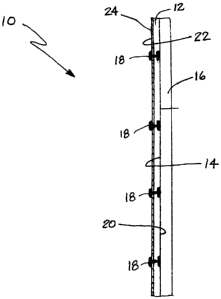
[0016] Figure 1 is a cross-sectional view of a garage door including the
insulation system of the present invention.
[0017] Figure 2 is rear (a.k.a interior) view of a garage door including
the
insulation system of the present invention.
[0018] Figure 2A is a detailed view of one possible embodiment of the
garage
door panel incorporating a raised contour in the doorway.
[0019] Figure 3 is a side elevational view of a securing clip of the
present
invention.
[0020] Figure 4 is a side elevational view showing two cooperating clips
used
to secure a blanket of insulation material to a panel of a garage door.
[0021] Figure 5 is a cross section of the clip with the two connectors
fully
seated, taken along line 55 of Figure 4.
[0022] Figure 6 is a top plan view of an installation kit of the present
invention.
DETAILED DESCRIPTION
[0023] Reference is now made to Figure 1 generally illustrating the
insulation
system 10 of the present invention. The insulation system comprises a layer of
insulation material 12 that is affixed to a major surface 14 of a panel 16 by
at least one
securing clip 18. Four securing clips 18 are illustrated in Figure 1. It
should be
appreciated, however, that substantially any number of securing clips 18 may
be
utilized as suited for any particular application.
4
CA 02652351 2009-02-04
[0024] As illustrated in Figure 1, the insulation material 12 includes a
first
side 20 and a second side 22. The first side 20 of the insulation material 12
is
provided adjacent to the major surface 14 of the panel 16. An optional facing
24 may
be provided on the second side 22 of the insulation material 12. When properly
mounted, each securing clip extends through the insulation material 12 and the
optional facing 24, if it is present. The facing 24 may be made from any
suitable
facing material including, but not limited to, polymers, such as vinyl, nylon
or
polyester, polymer films, paper, foil, cloth, woven or non-woven fabric or
combinations thereof.
[0025] The insulation material 12 may be any insulation material known,
including but not limited to, fiberglass insulation batting, mineral wool,
polymer
fibers, foams, blown-in foams, flexible foams, natural fibers and combinations
thereof. In one embodiment, the insulation material 12 may have an R-value of
between about 2 to about 100, or about 2 to about 50, or about 2 to about 40,
or about
2 to about 30, or about 2 to about 20, or about 2 to about 10. The panel 16
may be
any panel including, but not limited to, walls, doors and garage doors. The
insulation
system may also be used on industrial doors, delivery trucks, trailers, sheds,
pet
enclosures, metal buildings, ice shanties, hunting blinds, campers, boats or
any other
structure having panels where insulation may be necessary. Such panels 16 may
be
constructed from substantially any appropriate material including, but not
limited to,
polymer materials, wood, metal, steel, fiberglass composite materials and the
like.
[0026] As illustrated in Figure 2, the insulation system 10 of the present
invention is particularly useful on a garage door 26. The illustrated garage
door 26
includes two rows of panels 16. Four panels 16 are provided in each row. The
height
of the garage door 26 is determined by the number of panels 16 used and is
equivalent
to the height of the garage entry opening. The width of the two rows of panels
16 is
equivalent to the width of the garage entry opening so that the height and
width of the
garage door is equivalent to the height and width of the garage entry opening.
A
frame member 30 is provided at the top of each panel 16. Similarly, a frame
member
32 is provided at the bottom of each panel 16. The two rows of panels 16 are
joined
together at the mid section by the frame members 34. Similar frame members 36
are
provided at the ends of the panel rows and define the left and right margins
of the
garage door 26. A series of hinges 38 connect the adjacent frame members 34,
36.
CA 02652351 2009-02-04
These hinges 38 allow the garage door 26 to fold during opening and closing.
Typically a sealing member 40 is provided at the bottom of the garage door 26
to seal
between the door and an underlying concrete pad.
[0027] As illustrated in Figure 2A one or more of the panels 16 may have
a
major surface 14 that is contoured. Thus, the panel 16 carries a top frame
member 30
and a bottom frame member 32. The major face 14 includes a door tray 28
comprising a raised contour. Typically the layer of insulation material 12 is
sufficiently resilient and compressible to accommodate the raised contour of
the door
tray 28. However, it should be appreciated that the layer of insulation
material 12
may alternatively, be manufactured to include a cavity to accommodate the door
tray
28 if desired.
[0028] As best illustrated in Figures 2 and 4, at least one clip,
generally
designated by reference numeral 18 is utilized to secure the layer of
insulation
material 12 to the major surface 14 of each panel 16. In the illustrated
embodiment,
each clip 18 is affixed to the panel 16 with an adhesive such as a pressure
sensitive
adhesive as manufactured by MACtac of Stow, Ohio. In the embodiment
illustrated
in Figure 2, two clips 18 are provided to secure each layer of insulation 12
to each
panel 16.
[0029] As best illustrated in Figures 3-5, each clip 18 comprises first
and
second connectors 44, 44'. In the illustrated embodiment the first and second
connectors 44, 44' are identical. As best illustrated in Figure 3, each
connector 44
includes a head 46. In the illustrated embodiment the head 46 is enlarged and
disc
shaped. Two diametrically-opposed resilient latching elements 48 project from
the
head 46. A first locking shoulder 50 extends at least partially between the
latching
elements 48. A second locking shoulder, not illustrated in Figure 3 but shown
in
Figure 5 at 51', is provided opposite the first locking shoulder 50'. At least
one
latching element 48 of the two diametrically-opposed resilient latching
elements 48
includes a latching shoulder 52 adjacent a distal end opposite the head 46
(two
latching shoulders 52 are illustrated in Figure 3).
[0030] As further illustrated in Figure 3, at least one latching element
48
includes beveled side walls 56 and a pair of opposed, projecting detents 54
adjacent
the distal end. In addition a series of aligned notches 58 are provided in the
beveled
side walls 56. The last of the notches 58 is elongated to allow for full
seating of the
6
mimmomm.
CA 02652351 2009-02-04
connectors 44. Further, a first cam surface 60 is provided adjacent the
latching
shoulder 52 and the distal end of the connector 44 and a second cam surface 62
is
provided adjacent the locking shoulder 50. Another second cam surface is
provided
on the opposite side of the connector 44 but it is not visible in Figure 3.
[0031] First and second connectors 44 and 44' are
interconnected as illustrated
in Figures 4 and 5 by rotating one of the connectors 44 through 900 so that
the
latching elements 48, 48' of the two connectors are 90 out of phase. The two
connectors 44, 44' are then pushed together (note action arrows A in Figure
4). When
fully seated, the first and second latching shoulders 52 of the first
connector 44
engage the opposed locking shoulders 50', 51' of the second connector 44'. The
cooperating first and second cam surfaces 60, 62' allow for smooth
interconnection.
As the connectors 44, 44' are pushed together, the projecting detents 54 of
the first
connector 44 engage in the notches 58' of the second connector 44' to provide
a
sensory signal to the user that the connectors 44, 44' are properly aligned
and moving
toward complete connection. The final click that signals full seating occurs
when the
latching shoulders 52 snap into the cavities 66' of the second connector 44'
and
engage with the cooperating locking shoulders 50', 51'. It should be
appreciated that
the detents (not shown) of the connector 44' engage in the notches (not shown)
of the
connector 44 and the latching shoulders (not shown) of the connector 44'
engage the
locking shoulders (not shown) of the connector 44 at the opposite end of the
clip 18
when the connectors 44, 44' are fully seated. The resilient nature of the
latching
elements 48, 48' ensures the positive connection. The enlarged head 46'
engages a
significant surface area of the insulation material 12 or optional facing 24
so as to
prevent the insulation material from pulling off the connector 18 under the
pull of
gravity and during operation of the garage door 26.
[0032] The method of installing a layer of insulation
material 12 on a panel 16
will now be described in detail with reference to Figure 4. The method
includes
affixing at least one clip 18 to a major surface 14 of a panel 16. More
specifically, the
first connector 44 of the clip 18 may be affixed to the major surface 14 by
means of
an adhesive such as a pressure sensitive adhesive. This is followed by the
positioning
of a portion or section of insulation material 12 over the first connector 44
so that the
first connector extends through the insulation material. It should be noted
that the
insulation material 12 may be cut or slit at the point of insertion so as to
more easily
7
CA 02652351 2009-02-04
permit the connector 44 to extend through the layer 12. When the layer of
insulation
material 12 is properly seated on the connector 44, the first side 20 of the
insulation
material abuts the major surface 14 of the panel 16. Further, the distal end
of the
connector 44 extends through the optional facing 24 on the second side 22 if
that
facing is present.
[0033] As shown in Figure 2, two clips 18 may be installed to secure each
insulation layer 12 to each panel 16 of a garage door 26. Of course, it should
be noted
that fewer or more clips may be used depending on the size of the panel 16 and
the
size and/or weight of the insulation layer 12. Further, depending on the
application,
the insulation layer 12 may be one large piece or several smaller pieces. As
illustrated
in Figure 2, a garage door 26 includes eight panels 16 with each panel 16
being
covered by a single layer and section of insulation material 12 and each layer
of
insulation material being held in place by two clips 18. Of course, it should
also be
appreciated that more than one layer of insulation may be attached to the
panels 16 if
desired.
[0034] Reference is now made to Figure 6 illustrating a garage door
insulating
kit 70 of the present invention. The kit 70 comprises at least eight sections
of
insulation material 12 and at least sixteen securing clips 18. As further
illustrated, the
insulating kit 70 may also include a pair of vinyl gloves 72 and installation
instructions 74. In one possible embodiment the securing clips 18 have pre-
applied
adhesive 78 on at least one end. Further, it should be appreciated that the
insulation
material 12 may include the optional vinyl facing 24 and/or at least two pre-
cut slits
76 through which the clips 18 are secured.
[0035] The foregoing description of the preferred embodiments of the
present
invention have been presented for purposes of illustration and description. It
is not
intended to be exhaustive or to limit the invention to the precise form
disclosed.
Obvious modifications or variations are possible in light of the above
teachings.
[0036] For example, while the first and second connectors 44, 44 of the
illustrated clip 18 are identical, it should be appreciated that the
connectors are not
required to be identical. For example, the first and second connectors 44, 44'
may
comprise cooperating male and female components if desired. Further, the
connectors
44,44' may be secured together by snap action, friction fit, cooperating
threads or any
other appropriate interconnecting structure. Thus, a clip, such as that taught
in U.S.
8
CA 02652351 2009-02-04
Patent 5,176,465 may be used. Such a clip includes cooperating male and female
connectors. When the male connector is fully seated in the female connector,
holes in
the two connectors are aligned. A locking means, such as a pin, tab, screw or
nail is
then inserted in these holes to secure the two connectors of the clip
together. Further,
another type of clip may be used, such as snap rivets manufactured by ITW
Fastex
(Des Plaines, Illinois).
[0037] In the illustrated embodiment, an adhesive is utilized to affix
the clip
18 and, more specifically, the first connector 44, to the major surface 14 of
the panel
16. It should be appreciated that alternative securing means may be used
including,
for example, magnets, wire, screws, VELCRO, hook and loop fasteners, tape,
nails or
combinations thereof. Further, while the insulation layer 12 is illustrated
with only a
single optional facing layer 24, it should be appreciated that the insulation
layer may
be fully encapsulated with a facing on all sides or encapsulated on all sides
except the
side adjacent to the garage door 26.
[0038] The embodiments were chosen and described to provide the best
illustration of the principles of the invention and its practical application
to thereby
enable one of ordinary skill in the art to utilize the invention in various
embodiments
and with various modifications as are suited to the particular use
contemplated. All
such modifications and variations are within the scope of the invention as
determined
by the appended claims when interpreted in accordance with the breadth to
which
they are fairly, legally and equitably entitled. The drawings and preferred
embodiments do not and are not intended to limit the ordinary meaning of the
claims
in their fair and broad interpretation in any way.
9