Note: Descriptions are shown in the official language in which they were submitted.
CA 02652406 2008-11-14
WO 2007/145733 PCT/US2007/010905
COMPRESSIBLE OBJECTS HAVING A PREDETERMINED INTERNAL
PRESSURE COMBINED WITH A DRILLING FLUID TO FORM A
VARIABLE DENSITY DRILLING MUD
CROSS REFERENCE TO RELATED APPLICATIONS
[0001] This application claims the benefit of U. S. Provisional Application
No.
60/811,620, filed 7 June 2006.
FIELD OF THE INVENTION
[0002] This invention relates generally to a method to enhance drilling and
production operations from subsurface formations. More particularly, this
invention
relates to a method for selecting, fabricating and using compressible objects
with a
drilling fluid to form a variable density drilling mud that minimizes or
eliminates the
number of different sized casing strings utilized within a welibore.
BACKGROUND
[0003] This section is intended to introduce the reader to various aspects of
art, which may be associated with exemplary embodiments of the present
invention,
which are described and/or claimed below. This discussion is believed to be
helpful
in providing the reader with information to facilitate a better understanding
of
particular techniques of the present invention. Accordingly, it should be
understood
that these statements are to be read in this light, and not necessarily as
admissions
of prior art.
[0004] The production of hydrocarbons, such as oil and gas, has been
performed for numerous years. To produce these hydrocarbons, a wellbore is
typically drilled in intervals with different casing strings installed to
reach a
subsurface formation. The casing strings are installed in the wellbore to
prevent
collapse of the wellbore walls, to prevent undesired outflow of drilling fluid
into the
formation, and/or to prevent the inflow of fluid from the formation into the
wellbore.
Typically, the process of installing casing strings involves tripping, running
casing,
and cementing the casing strings. Because the casing strings in the different
intervals pass through already installed casing strings, the lower intervals
of the
casing strings typically have smaller diameters. In this manner, the casing
strings
CA 02652406 2008-11-14
WO 2007/145733 PCT/US2007/010905
-2-
are formed in a nested configuration that continue to decrease in diameter in
each of
the subsequent intervals.
[0005] In addition to the casing strings, a drilling mud is circulated within
the
welibore to remove cuttings from the well. The weight or density of the
drilling mud
is typically maintained between the pore pressure gradient (PPG) and the
fracture
pressure gradient (FG) for drilling operations. However, the PPG and FG
increase
along with the true vertical depth (TVD) of the well, which present problems
for
maintaining the drilling mud weight. If the weight of the drilling mud is
below the
PPG, the well may take a kick. A kick is an influx of formation fluid into the
wellbore,
which has to be controlled for drilling operations to resume. Also, if the
weight of the
drilling mud is above the FG, the drilling mud may leak off into the
formation. These
lost returns result in large volumes of drilling mud loss, which has to be
replaced for
the drilling operations to resume. Accordingly, the casing strings are
utilized to
assist in maintaining the weight of the drilling mud within the PPG and FG to
continue drilling operations to greater depths.
[0006] With subsurface formations being located at greater depths, the cost
and time associated with the forming the wellbore increases. For instance,
with the
nested configuration, the initial casing strings have to be sufficiently large
to provide
a welibore diameter of a specific size for the tools and other devices near
the
subsurface formations. As a result the diameter of the initial casing strings
is
relatively large to provide a final useable wellbore diameter. The large
diameter
increases the costs of the drilling operations because of the cost associated
with the
increased size of the casing string, increased volume of cuttings that have to
be
managed, and increased volume of cement and drilling mud utilized to form the
welibore. As such, the cost of typically drilling operations results in some
subsurface formations being economically unfeasible.
[0007] To reduce the diameter of casing strings, various processes are
utilized. For example, drilling operations may utilize variable density
drilling mud to
maintain the drilling mud within the PPG and FG. As noted in Intl. Patent
Application Publication No. WO 2006/007347 to Polizzotti et al., compressible
objects may include compressible or collapsible hollow objects of various
shapes or
structures. These compressible objects, which are selected to achieve a
favorable
CA 02652406 2008-11-14
WO 2007/145733 PCT/US2007/010905
-3-
compression in response to pressure and/or temperature changes. These
compressible objects may be recirculated as part of the variable density
drilling mud
to provide volume changes that reduce the number of intermediate casing string
intervals in the wellbore.
[0008] However, the use of compressible objects in the variable density
drilling mud can be challenging. For instance, the compressible objects have
to be
fabricated to provide a certain amount of compression and to be resilient.
Further,
the compressible objects have to be designed to compress at certain pressures
to
provide the volume changes in specific intervals within the wellbore. In
addition, the
drilling fluid, which is combined with the compressible objects, may be
selected and
include certain additives to interact with the compressible objects to enhance
the
variable density drilling mud. As such, there is a need for a method for
selecting and
fabricating compressible objects for use with drilling fluids to form the
variable
density drilling mud.
[0009] Other related material may be found in at least U.S. Patent No.
3,174,561; U.S. Patent No. 3,231,030; U.S. Patent No. 4,099,583; U.S. Patent
No.
5,881,826; U.S. Patent No. 5,910,467; U.S. Patent No. 6,156,708; U.S. Patent
No.
6,422,326; U.S. Patent No. 6,497,289; U.S. Patent No. 6,530,437; U.S. Patent
No.
6,588,501; U.S. Patent No. 7,108,066; U.S. Patent Application Publication No.
2005/0113262; U.S. Patent Application Publication No. 2005/0284661; and Intl.
Patent Application Publication No. WO 2006/007347.
SUMMARY
[0010] In one embodiment, a compressible object is described. The
compressible object including a shell that encloses an interior region,
wherein the
compressible object has an internal pressure (i) greater than 200 pounds per
square
inch (psi) at atmospheric pressure and (ii) selected for a predetermined
external
pressure, wherein external pressures that exceed the internal pressure reduce
the
volume of the compressible object and wherein the shell is designed to
compensate
for localized strains of the compressible object during expansion and
compression of
the compressible object. The internal pressure may also be greater than 500
pounds
per square inch at atmospheric pressure, greater than 1500 pounds per square
inch
at atmospheric pressure, or greater than about 2000 pounds per square inch at
CA 02652406 2008-11-14
WO 2007/145733 PCT/US2007/010905
-4-
atmospheric pressure. Further, the internal pressure may be in a range from
200 psi
up to the tensile strength of the shell material at atmospheric pressure, in a
range
from 2000 psi to the tensile strength of the shell material at atmospheric
pressure,
and/or in a range from 1500 psi to 3500 psi at atmospheric pressure.
10011] In a first alternative embodiment, a drilling mud is described. The
drilling mud including compressible objects, wherein each of at least a
portion of the
compressible objects has an internal pressure (i) greater than 200 pounds per
square inch at atmospheric pressure and (ii) selected for a predetermined
pressure,
wherein external pressures that exceed the internal pressure reduce the volume
of
the compressible object wherein the shell is designed to compensate for
localized
strains of the compressible object during expansion and compression of the
compressible object. Further, the drilling mud includes a drilling fluid,
wherein the
density of the drilling mud changes due to the volume change of the
compressible
objects in response to pressure changes as the drilling fluid and compressible
objects circulate toward the surface of a wellbore.
[0012] In a second alternative embodiment, a method associated with drilling
a well is described. The method includes selecting compressible objects,
wherein
each of at least a portion of the compressible objects has an internal
pressure (i)
greater than 200 pounds per square inch at atmospheric pressure and (ii)
selected
for a predetermined external pressure, wherein external pressures that exceed
the
internal pressure reduce the volume of the compressible object; selecting a
drilling
fluid; introducing the compressible objects to the drilling fluid to form a
variable
density drilling mud, wherein the variable density drilling mud provides a
density
between a pore pressure gradient and a fracture pressure gradient for at least
one
interval of a well as the variable density drilling mud circulates toward the
surface of
the well; and drilling a wellbore with the variable density drilling mud at
the location of
the well. Further, once the wellbore is formed, hydrocarbons may be produced
from
the wellbore.
[0013] In a third alternative embodiment, a method for forming a variable
density drilling mud is described. The method includes selecting compressible
objects, wherein each of at least a portion of the compressible objects has an
internal pressure (i) greater than 200 pounds per square inch at atmospheric
CA 02652406 2008-11-14
WO 2007/145733 PCT/US2007/010905
-5-
pressure and (ii) selected for a predetermined well pressure, wherein external
pressures that exceed the internal pressure reduce the volume of the
compressible
object; selecting a drilling fluid to be combined with the compressible
objects;
blending the compressible objects with the drilling fluid to form a variable
density
drilling mud, wherein the variable density drilling mud maintains a density
between a
pore pressure gradient and a fracture pressure gradient for at least one
interval of a
well as the variable density drilling mud circulates toward the surface of a
well.
[0014] In a fourth alternative embodiment, a system associated with drilling a
wellbore is described. The system includes a wellbore; a variable density
drilling
mud disposed in the wellbore, wherein the variable density drilling mud has
compressible objects and a drilling fluid, wherein each of at least a portion
of the
compressible objects 'has an internal pressure (i) greater than 200 pounds per
square inch at atmospheric pressure and (ii) selected for a predetermined well
pressure, wherein external pressures that exceed the internal pressure reduce
the
volume of the compressible object. The system further including a drilling
string
disposed within the wellbore and a bottom hole assembly coupled to the
drilling
string and disposed within the wellbore.
BRIEF DESCRIPTION OF THE DRAWINGS
[0015] The foregoing and other advantages of the present technique may
become apparent upon reading the following detailed description and upon
reference
to the drawings in which:
[0016] FIG. I is an illustration of an exemplary drilling system in accordance
with certain aspects of the present techniques;
[0017] FIGs. 2A-2D are an exemplary chart and embodiments of a
compressible object in accordance with aspects of the present techniques;
[0018] FIGs. 3A-3C are exemplary embodiments of a compressible object in
different states in accordance with aspects of the present techniques;
[0019] FIG. 4 is an exemplary chart of different shaped compressible objects
in accordance with aspects of the present techniques;
CA 02652406 2008-11-14
WO 2007/145733 PCT/US2007/010905
-6-
[00201 FIG. 5 is an exemplary flow chart of the selection and use of a
variable density drilling mud for the drilling system of FIG. 1 in accordance
with
certain aspects of the present techniques;
[0021] FIG. 6 is an exemplary flow chart of the selection and fabrication of
compressible objects for the flow chart in FIG. 5 in accordance with certain
aspects
of the present techniques;
[0022] FIG. 7 is an exemplary chart relating to the shape of compressible
objects in accordance with certain aspects of the present techniques;
[0023] FIGs. 8A-8B are exemplary embodiments of fabrication processes
utilized in the flow chart of FIG. 6 in accordance with certain aspects of the
present
techniques;
[0024] FIG. 9 is an exemplary flow chart for a fabrication process utilized in
the flow chart of FIG. 6 with compressible objects having a foam template in
accordance with certain aspects of the present techniques;
[0025] FIG. 10 are exemplary embodiments of compressible objects
fabricated from the flow chart in FIG. 9 in accordance with certain aspects of
the
present techniques;
10026] FIGs. 11A-11 B are exemplary embodiments of fabrication processes
utilized in the flow chart of FIG. 6 in accordance with certain aspects of the
present
techniques;
[0027] FIGs. 12A-12C are embodiments of a compressible object having a
flange in accordance with aspects of the present techniques; and
[0028] FIG. 13 is an exemplary chart relating to the addition of a flange to
the
compressible object in accordance with certain aspects of the present
techniques.
DETAILED DESCRIPTION
[0029] In the following detailed description and example, the invention will
be
described in connection with its preferred embodiments. However, to the extent
that
the following description is specific to a particular embodiment or a
particular use of
CA 02652406 2008-11-14
WO 2007/145733 PCT/US2007/010905
-7-
the invention, this is intended -to be illustrative only. Accordingly, the
invention is not
limited to the specific embodiments described below, but rather, the invention
includes all alternatives, modifications, and equivalents falling within the
true scope
of the appended claims.
[0030] The present technique is directed to a method, composition and
system for selecting, fabricating, and utilizing compressible objects in a
variable
density drilling mud. In particular, the compressible objects may be utilized
with a
drilling fluid to form the variable density drilling mud for drilling
operations in a well.
The compressible objects and the drilling fluid are selected to maintain the
drilling mud
weight between the pore pressure gradient (PPG) and the fracture pressure
gradient
(FG) within a welibore. Specifically, under the present techniques, the
compressible
objects have an internal pressure greater than about 200 pounds per square
inch at
atmospheric pressure, greater than about 500 pounds per square inch at
atmospheric pressure, or more preferably greater than about 1500 pounds per
square inch at atmospheric pressure. The compressible objects may include
compressible or collapsible hollow objects of various shapes, such as spheres,
cubes, pyramids, oblate or prolate spheroids, cylinders, pillows and/or other
shapes
or structures, which are selected to achieve a favorable compression in
response to
pressure and/or temperature changes. Also, as discussed below, the
compressible
objects may include polymers, polymer composites, metals, metal 'alloys,
and/or
polymer or polymer composite laminates with metals or metal alloys, which are
fabricated in a variety of methods. Accordingly, various methods and systems
are
described to select and fabricate the compressible objects. Further, it should
be
noted that the following methods and procedures are not limited to drilling
operations, but may also be utilized in completion operations, or any
operations
benefiting from variable density fluids.
[0031] Turning now to the drawings, and referring initially to FIG. 1, an
exemplary drilling system 100 in accordance with certain aspects of the
present
techniques is illustrated. In the exemplary drilling system 100, a drilling
rig 102 is
utilized to drill a well 104. The well 104 may penetrate the surface 106 of
the Earth
to reach the subsurface formation 108. As may be appreciated, the subsurface
formation 108 may include various layers of rock that may or may not include
hydrocarbons, such as oil and gas, and may be referred to as zones or
intervals. As
CA 02652406 2008-11-14
WO 2007/145733 PCT/US2007/010905
-8-
such, the well 104 may provide fluid flow paths between the subsurface
formation
108 and production facilities (not shown) located at the surface 106_ The
production
facilities may process the hydrocarbons and transport the hydrocarbons to
consumers. However, it should be noted that the drilling system 100 is
illustrated for
exemplary purposes and the present techniques may be useful in circulating
fluids in
a wellbore for any purpose, such as performing drilling operations or
producing fluids
from a subsurface location.
[0032] To access the subsurface formation 108, the drilling rig 102 may
include drilling components, such as a bottom hole assembly (BHA) 110,
drilling
strings 112, casing strings 114 and 115, drilling fluid processing unit 116
for
processing the variable density drilling mud 118 and other systems to manage
wellbore drilling and production operations. Each of these drilling components
is
utilized to form the wellbore of the well 104. The BHA 110 may include a drill
bit and
be used to excavate formation, cement or other materials from the wellbore.
The
casing strings 114 and 115 may provide support and stability for the access to
the
subsurface formation 108, which may include a surface casing string 115 and an
intermediate or production casing string 114. The production casing string 114
may
extend down to a depth near or through the subsurface formation 108. The
drilling
fluid processing unit 116 may include equipment that may be utilized to manage
the
variable density drilling fluid. For example, the drilling fluid processing
unit 116 may
include shakers, separators, hydrocyclones and other suitable devices (e.g.,
as
described in International Patent Application No. PCT/US2007/003691, filed
13 February 2007.
[0033] During drilling operations, the use of a variable density drilling mud
118 as a drilling mud allows the operator to drill deeper below the surface
106,
maintain sufficient hydrostatic pressure, prevent an influx of formation fluid
(gas or
liquid), and remain below an FG that the subsurface formation 108 can support.
As
noted in Patent Application Publication No. WO 2006/007347 to Polizzotti et
al.,
which is incorporated by reference, compressible objects may preferably have a
compression ratio that is tailored to create a mud weight that lies between
the pore
pressure gradient (PPG) and the fracture gradient (FG) over the depth interval
specific to the drilling application. That is, the compressible objects should
have
substantially recoverable load bearing walls and low permeability for the gas
within
CA 02652406 2008-11-14
WO 2007/145733 PCT/US2007/010905
-9-
the compressible objects. Substantially recoverable is defined to mean that
the
accumulation of plastic strain in the shell wall as a consequence of repeated
cycling
of the compressible objects between the surface and the bottom of the wellbore
does
not cause substantial failure of the load bearing wall or significant loss of
the internal
gas pressure during repeated cycles (i.e. two or more cycles) as the well is
drilled to
the target depth. Also, low permeability is defined to mean that the internal
pressure
of the compressible objects, while in use, remains within acceptable limits
for a
predetermined time period required to drill the wellbore to the target depth.
[0034] While adding compressible objects to drilling mud to control the
density of the drilling mud based on depth has been described in Patent
Application
Publication No. WO 2006/007347 to Polizzotti et al., the design of
compressible
objects and selection of a drilling fluid- to provide this functionality is
difficult. In
particular, the repeated compression cycles typically experienced by a
recirculating
variable density drilling mud within the constraints imposed by the mechanical
properties of existing materials may be a limitation for the compressible
objects. As
such, the process of fabricating the compressible objects may have to include
various factors that influence the durability and performance of the
compressible
objects, as discussed further below.
[0035] To begin, it should be noted that large compression ratios are
required to achieve the desired change in the drilling fluid density with
depth within
the limits set by the maximum volume fraction of the compressible objects
allowed by
the effect of the compressible objects on the fluid rheology, as described in
Patent
Application No. WO 2006/007347. Accordingly, the compressible objects should
have certain properties configured to provide large compression ratios and to
begin
compression within certain pressure ranges or levels. The compression ratio of
a
hollow object, which is one embodiment of the compressible objects, may be
limited
by the ratio of the initial uncompressed volume (i.e. uncompressed or expanded
state) divided by the volume occupied by the material comprising the shell
wall plus
the volume of the compressed gas inside the shell for the delta pressure OP of
the
wellbore interval of interest. Large compression ratios are provided by the
wall of the
compressible objects being thin and flexible. Accordingly, the compressible
objects
may preferably be designed such that the compression and re-expansion of the
compressible objects may be accomplished without significant permanent
CA 02652406 2008-11-14
WO 2007/145733 PCT/US2007/010905
-10-
deforrnation of the walls (i.e., permanent deformation leading to early
fatigue failure
of the walls of the compressible object).
[0036] In addition, the predetermined external pressure or depth of
compression and the predetermined compression interval of the compressible
objects may be tailored to provide a change in the density of the drilling mud
at or
near specific depths within the wellbore. Typically, object compression that
begins at
the surface has limited value. In these applications, the compressible objects
compress from the surface for a predetermined compression interval or range,
which
extends down to a specific depth. As a result, these compressible objects may
be
utilized for some specific land drilling applications, but may not be useful
in
deepwater environments or deeper drilling intervals. To provide a change in
the
density over a specific predetermined pressure interval for specific depths or
external
pressure, the starting depth and depth interval for the predetermined pressure
interval over which the compression occurs may preferably be adjusted by the
compressible objects. For example, the initial internal pressure of the
compressible
object may be selected based on the depth at which a transition in the
compressibility is desired. At depths in the mud column (i.e. drilling fluid
within the
wellbore) for which the pressure is below the initial internal pressure of the
compressible objects, the Young's Modulus of the wall material and the
differential
pressure across the wall material control the volume change of the
compressible
objects. At depths for which the pressure in the mud column is above the
initial
internal pressure, the volume change of the compressible objects gradually
becomes
dominated by the compressibility of the gas. That is, the predetermined
compression interval is a pressure range from an external pressure that is
about
equal to the internal pressure of the compressible object to an external
pressure that
substantially compresses the compressible object (i.e. compresses the
compressible
object into a compressed state, which is discussed further below). As such,
compressible objects may be fabricated to begin compression at or near a
specific
pressure or depth and/or for a specific predetermined pressure interval to
provide a
density change in specific portions or intervals of the wellbore.
[0037] To compress at a specific depth, the walls of the compressible objects
may be designed to maintain a predetermined internal pressure. The initial
internal
pressure of the compressible objects for a given drilling mud density is
determined
CA 02652406 2008-11-14
WO 2007/145733 PCT/US2007/010905
-11-
by the depth at which a transition to gas compression is dominated by volume
change of the compressible objects. Typically, an internal pressure greater
than
about 200 psi (pounds per square inch) at atmospheric pressure, greater than
500
psi at atmospheric pressure, greater than 1500 psi at atmospheric pressure or
more
preferably greater than 2000 psi at atmospheric pressure, may be utilized. For
a
given initial internal pressure, the achievable object compression ratio is
dependent
on the ratio of the wall thickness to the effective diameter of the
compressible object.
While the wall thickness is preferably as thin as possible, the lower limit of
the wall
thickness is defined by the minimum thickness capable of containing the
desired
internal gas pressure at an external pressure of about I atmosphere, which is
typically encountered at the surface 106. Accordingly, a material with a
tensile
strength greater than 10,000 psi may typically be utilized, as discussed
below, to
maintain the internal pressure for the compressible object. As such, the
internal
pressure may be in a range from 200 psi up to the tensile strength of the
shell
material at atmospheric pressure, in a range from 2000 psi to the tensile
strength of
the shell material at atmospheric pressure, and/or in a range from 1500 psi to
3500
psi at atmospheric pressure.
[0038] Further, for a given internal pressure and diameter of a compressible
object, the minimum wall thickness that may be used is therefore defined by
the
elastic limit of the tensile strength of the wall material. Within these
strength
limitations, it is desirable to minimize the wall thickness because the ratio
of the
volume of the wall material to the total volume of the compressible object
sets an
upper limit on the magnitude of the achievable compression ratio, as noted
above.
Accordingly, while the compressible object may include a variety of shapes,
such as
cubes, pyramids, oblate or prolate spheroids, cylinders, pillows, for example,
spherical and elliptical objects with spherical or near spherical inflated
geometries
are useful for reasons related to the optimization of the compressible mud
rheology.
Accordingiy, the compressible objects may include elliptical and/or spherical
objects,
such as pressurized hollow metallic spherical and elliptical objects, with an
aspect
ratio (i.e., the ratio,of the major diameter to the minor diameter) of between
about 1
and 5 to provide compression ratios of up to 5:1 or greater.
[0039] The design of the compressible object may be further complicated by
structural instabilities. For instance, a spherical object for a given
internal pressure
CA 02652406 2008-11-14
WO 2007/145733 PCT/US2007/010905
-12-
and diameter may be restricted by structural instabilities characteristic of
the
spherical object's architecture. The structural instabilities may include
local strains,
such as equatorial buckling instability during the inflation phase and the cap
buckling
instability during the compression phase. As such, the design of the
compressible
object may also be adjusted to compensate for, or reduce the localized strains
and
instabilities during expansion and compression of the compressible objects.
Accordingly, the Finite Element Analysis (FEA) modeling of a spherical object,
which
may be one embodiment of a compressible object, is discussed further below, as
shown in FIGs. 2A-2D.
10040] FIG. 2A is an exemplary chart and embodiments of a compressible
object. In the chart 200, a compressible object is a nearly spherical object,
which
has an aspect ratio of about 1.0 and wall thickness of 10 microns. The aspect
ratio
of an object is defined as the ratio of the major axis over the minor axis,
which is
discussed further below.
[0041] In FIG. 2A, the chart 200 of maximum strain 202 versus compression
ratio 204 of the elastic spherical object is shown. The maximum strain 202 is
the
largest strain at any point on the compressible object in that state. The
chart 200,
which is generated from a FEA modeling tool, such as.ABAQUST"' FEA, includes a
response curve 206 of the spherical object in different states. As indicated
by the
response curve 206, a linear elastic deformation in excess of about 12% is
required
to provide a compression ratio of at least 5:1. Along the response curve 206,
the
maximum elastic deformation does not occur uniformly over the object surface
during compression, but is localized due to buckling instabilities during
compression.
[0042] Specific examples of the localized strain on the object are shown in
FIG. 2B. In FIG. 2B, a partial view of an object 210, such as a spherical or
elliptical
object, subjected to compression pressure that is external to the object is
shown.
The elastic deformation of the object 210 as it is compressing is dominated by
strain
localization associated with a cap buckling instability, which is indicated by
the
depressed region 214. The cap buckling instability is a collapse of the
depressed
region 214 due to the inability of the structure to resist the external
pressure loaded
on that region. In particular, the regions 216 are the locations or areas of
the largest
CA 02652406 2008-11-14
WO 2007/145733 PCT/US2007/010905
-13-
localized strain, which are plotted in the response curve 206 of FIG. 2A. The
severity
of this instability has been shown to increase with increasing wall thickness
[0043] Based on the discussion above, the compressible object should have
a tensile strength sufficient to handle the internal pressure and a
recoverable linear
elongation or elastic strain large enough to handle the required deformation.
If the
spherical or near spherical compressible object shell is assumed to be
metallic, then
the metal or metal alloy should have sufficient tensile strength within its
elastic limit
to contain the internal pressure and at least 12% recoverable linear
elongation.
While the tensile strength may be easily achieved, few metals or metal alloys
have
an elastic strain limit in excess of 1%. If the recoverable linear elongation
of greater
than 1% is desired, typical materials may not be sufficient. The exceptions to
this
limitation are some amorphous metal alloys with a limit of elastic strain
approaching
about 2% and the shape memory alloys (e.g., the Nitol family of NiTi alloys),
which
exhibit pseudo-elastic strains of up to 8% with less than about 0.1 %
permanent
deformation. Accordingly, typical metal or metal alloys cannot provide the at
least
12% recoverable linear elongation if -a spherical structure is utilized as the
initial
shape.
[0044] To provide the required recoverable linear elongation, the
compressible object may be designed to divide the deformation of the
compressible
object into different states. For instance, the compressible objects may have
three
different states, such as an initial state, an expanded state, and a
compressed state.
In one embodiment the initial state may be, for example, an oblate spheroid
with an
aspect ratio less than 1Ø FIG. 2C shows an oblate spherical object 220
having a
major axis 222 and a minor axis 224. As noted above, the aspect ratio of the
object
220 in the initial state is defined as the ratio of the major axis 222 over
the minor axis
224. With these states, the required deformation of the compressible object is
divided into two phases. The overall required deformation may be divided
between
an expanded state and a compressed state. The inflation or first phase
involves the
expansion of the compressible object from the initial state to the expanded
state,
which may be limited by the tensile strength of the wall material and/or
structural
instabilities of the fully expanded compressible object characteristic of the
initial state
of the compressible object architecture and the initial internal pressure.
CA 02652406 2008-11-14
WO 2007/145733 PCT/US2007/010905
-14-
[0045] In particular, in FIG. 2D, an oblate spherical object 230 with an
initial
4:1 aspect ratio, a 10 micron wall thickness and an inflated internal pressure
of 10.9
MPa (mega-pascals) is subjected to internal pressure that expands the oblate
spherical object 230. The maximum in the elastic deformation of the object 230
as it
is expanding is dominated by strain localization associated with equatorial
wall
buckling, which is indicated by the depressed regions 232 and 234. The
equatorial
wall buckling instability is a collapse of the regions 232 and 234 due to the
contraction of the equatorial belt associated with the inflation of the oblate
spherical
object 230. In general it has been shown that the susceptibility of the
compressible
object to equatorial buckling increases as the initial aspect ratio of the
compressible
object increases, the internal pressure increases and the wall thickness
decreases.
In this example, the expanded state may be an equilibrium state with the
outside
pressure of one atmosphere and where the compressible object has a spherical
or
near spherical shape (i.e. aspect ratio of about 1.0).
[0046] The second phase may involve the compression of the object from the
expanded state back to about the initial state during which the deformation
due to
the initial expansion is nearly fully recovered and a subsequent further
compression
to the fully compressed state, which may again be limited by the elastic
strain of the
wall material of the fully compressed object. The compressed state may be, for
example, an equilibrium compressed shape based on the hydrostatic compression
exerted on the compressible object at a certain downhole depth. Accordingly,
the
compressible objects may be designed using these states to provide a suitable
compression ratio that is beneficial for use within a wellbore.
[0047] FIGs. 3A-3C are exemplary embodiments of a compressible object in
different states in accordance with aspects of the present techniques. In the
embodiments of FIGs. 3A-3C, FEA modeling is utilized to demonstrate the
different
states of a compressible object, which is an ellipsoid in this example. Each
of these
FIGs. 3A-3C is a partial view of the compressible object in different states.
As
shown in FIG. 3A, a elliptical object may be in the initial state 300 and have
a major
axis 302 and a minor axis 304 with the aspect ratio being 4:1. In FIG. 3B, the
elliptical object may be in the expanded state 306 and have a major axis 308
and
minor axis 310 and an aspect ratio less than (i.e. <) 4:1. In FIG. 3C, the
elliptical
object may be in compressed state 312 and have a major axis 314 and minor axis
of
CA 02652406 2008-11-14
WO 2007/145733 PCT/US2007/010905
-15-
316 and an aspect ratio greater than (i.e. >>) 4:1. Accordingly, the aspect
ratio for
each of the different states 300, 306 and 312 may differ based on the
expansion
and/or compression of the elliptical object. Compressible objects having
different
initial aspect ratios is discussed further in FIG. 4.
[0048] FIG. 4 is an exemplary chart of different initial shaped compressible
objects in accordance with aspects of the present techniques. FEA modeling is
utilized to generate the chart 400 of the maximum strain 402 versus
compression
ratio 404 for different compressible objects having a wall thickness of 15
microns.
The chart 400 includes a first response. curve 406 for a spherical object, a
second
response curve 407 of an elliptical object having a 2:1 aspect ratio, a third
response
curve 408 of an elliptical object having a 3:1 aspect ratio, a fourth response
curve
409 of an elliptical object having a 4:1 aspect ratio, which may be the
elliptical object
in FIGs. 3A-3C, and a fifth response curve 410 of an elliptical object having
a 5:1
aspect ratio.
[0049] As indicated by the response curves 406-410, the maximum strain
increases and decreases between the various states. For objects with an
initial
aspect ratio less than 3:1, the maximum linear elastic strain behavior for
compression ratios less than 3:1 is dominated by cap buckling instabilities
described
above. For compressible objects with an initial aspect ratio greater than 3:1,
the
maximum strain decreases from the expanded state to a minimum value at or
close
to the initial state, which is a global minimum for the strain on the
compressible
object. Then, the maximum strain increases from the initial state until the
fully
compressed state is reached. As such, the maximum strain at the initial state
of the
compressible objects is near zero as indicated by the response curves 406-410.
This aspect is clearly demonstrated by the fourth response curve 409. Along
the
response curve 409, the expanded state is located at the point 416, the
initial state is
located at the point 414 and the compressed state is located at the point 412.
Clearly, the initial state of the compressible object has the lowest strain in
comparison to the expanded and compressed states. In addition, this
compressible
object has a maximum strain of about 0.085, which is about the value of the
maximum recoverable strain for the austenite to martensite phase
transformation of
the Nitol family of alloys in their pseudo-elastic state. That is, the
response curve
409 indicates that the elliptical object having a 4:1 initial aspect ratio is
a suitable
CA 02652406 2008-11-14
WO 2007/145733 PCT/US2007/010905
-16-
structure and wall thickness to provide the specified compression ratio of
greater
than 5:1 with an internal pressure useful for the practice of the invention
disclosed in
International Patent Application Publication No. WO 2006/007347. Each of the
other
response curves 406-408 and 410 exceed the maximum recoverable strain of
0.085.
Strains above the austenite to martensite phase transformation completion
strain of
approximately 8% may experience permanent deformation resulting in limited
fatigue
life in cyclic deformation.
[0050] From this chart 400, the inflation and subsequent compression of the
compressible object is bounded by an equatorial buckling instability during
the
inflation phase and the cap buckling instability described earlier during the
compression phase. By modeling the inflation and subsequent compression, the
initial architecture of the compressible object may be designed to minimize
the
recoverable elongation for the specific compression ratio. In particular, for
a
compressible object of constant wall thickness fabricated from a NiTi shape
memory
alloy with an austenite to martensite phase transformation temperature below
about
0 C (Celsius) and a target expanded internal pressure of 1500 psig (pounds per
square inch gauge), the initial aspect ratio of the compressible object before
inflation
may preferably be between about 3 and 4 with a wall thickness between about 15
and 20 microns to avoid exceeding about 8% linear elongation anywhere in the
wall
of the compressible object for a compression ratio of up to 8:1. As noted
above, to
be useful for the practice of Patent Application No. WO 2006/007347, the alloy
should be in a pseudo-elastic condition. Ordinary shape memory alloys with
transformation temperatures above about 0 C are not useful for this
application.
The requirement of an austenite to martensite phase transformation temperature
below about 0 C recognizes that the alloy should remain pseudo-elastic over
the
entire temperature range encountered during operation of the compressible
objects
in the drilling mud.
[0051] Based on the modeling methods discussed above, compressible
objects may be designed of a certain material and having a specific
architecture to
provide specific compression ratios that are within the deformation
limitations of
existing materials. With these compression ratios, the compressible objects
may be
useful for certain applications, such as drilling and production operations,
which are
described above. As an example, the compressible objects may be useful if they
CA 02652406 2008-11-14
WO 2007/145733 PCT/US2007/010905
-17-
provide a recoverable compression ratio greater than or equal to five times
the
expanded state at a specific depth interval of interest. The compressible
objects
may be included in the variable density drilling mud in a volume fraction of
up to 40%
or 50% to provide a change in drilling mud density representative of typical
PPGs
and/or FGs. By changing the density of the drilling mud by adding up to 50% by
volume of small low-density, compressible objects, which may have a diameter
of
about 1 millimeter (mm), the pressure gradient within the wellbore may be
substantially controlled to reduce the number of casing strings utilized
within the
wellbore. In particular for a deep-water application, the number of casing
intervals
may be reduced substantially below that achievable with dual gradient or multi-
gradient systems without major modification of existing hardware or equipment.
As
such, the well cost may be reduced by up to 30 to 50% for certain
applications.
Accordingly, the selection of the compressible objects and fabrication of the
compressible objects is discussed further below in FIG. 5.
[0052] FIG. 5 is an exemplary flow chart of the selection and use of the
variable density drilling mud for the drilling system 100 of FIG. 1 in
accordance with
certain aspects of the present techniques. This flow chart, which is referred
to by
reference numeral 500, may be best understood by concurrently viewing FIGs. 1,
3A-3C and 4. In this flow chart 500, compressible objects and drilling fluid
may be
selected to formulate a variable density drilling mud for a well. These
compressible
objects may include objects that each have a shell enclosing an interior
region, and
wherein the compressible object has (a) an internal pressure (i) greater than
about
200 psi at atmospheric pressure, 500 psi at atmospheric pressure, 1500 psi at
atmospheric pressure and/or 2000 psi at atmospheric pressure, and (ii)
selected for
a predetermined external pressure, wherein extemal pressures that exceed the
internal pressure reduce the volume of the compressible object; (b) wherein
the shell
experiences less strain when the external pressure is about equal to the
internal
pressure than when the external pressure is above or below a predetermined
compression interval of the compressible object or wherein the shell is
configured to
experience less strain when the external pressure is about equal to the
internal
pressure than when the external pressure is greater than the internal pressure
or
less than the internal pressure; and/or (c) compressible objects having a
shell that
encloses an interior region at least partially filled with a foam. Then, the
variable
density drilling mud may be utilized to enhance the drilling operations of the
well.
CA 02652406 2008-11-14
WO 2007/145733 PCT/US2007/010905
-18-
This process may enhance the drilling operations by providing a variable
density
drilling mud that extends the drilling operations to further limit or reduce
the
installation of additional casing strings. Accordingly, drilling operations
performed in
the described manner may reduce inefficiencies from utilizing additional
casing
strings from drilling operations.
[0053] The flow chart begins at block 502. At block 504, the FG and PPG for
a well may be determined. For example, the FG and PPG may be obtained by
receiving information from the drilling location and/or performing calculation
to
estimate the FG and PPG. Then, compressible objects may be selected to provide
specific volumetric changes, as shown in block 506. The selection of
compressible
objects may include operational considerations, such as removal of the
compressible
objects from the drilling mud for re-circulation at the surface, limiting
potentially
detrimental effects of the high volume fraction of compressible objects on the
rheology of the drilling mud and facilitating the flow of the compressible
objects
through the pumps and orifices in the flow path. As such, the compressible
objects
may be sized to have an equivalent diameter between 0.1 millimeter (mm) and 50
mm, and/or preferably between 0.1 mm and 5.0 mm. The equivalent diameter is
defined as the diameter of a sphere of equal volume as the fully expanded
compressible object at atmospheric pressure. Further, the selection of
compressible
objects may include utilizing compressible objects of different sizes or
volumes at the
surface of the wellbore and/or different shapes to manage the viscosity
increases of
the drilling mud. The selection of the compressible objects is further
described in
FIG. 6.
[0054] At block 508, the drilling fluid may be selected. The drilling fluid,
which may include various weighting agents, may be selected to provide a
specific
density that may interact with the compressible objects to maintain the
drilling mud
density between the FG and PPG, which is discussed further below. The
compressible objects and the drilling fluid may be combined in block 510. The
combination of the compressible objects and the drilling fluid may involve
mixing or
blending the compressible objects with the drilling fluid, as described in
International
Patent Application No. PCT/US2007/003691, filed 13 February 2007. Further, the
compressible objects and the drilling fluid may be combined prior to shipping
to the
drilling location or shipped individually with the compressible objects and
the drilling
CA 02652406 2008-11-14
WO 2007/145733 PCT/US2007/010905
-19-
fluid being combined at the 'drilling location. It should be noted that the
compressible objects may be shipped in refrigerated vehicles, such as trucks
and
ships, to reduce risks associated with the release of internal pressure within
the
compressible objects.
[0055] At the drilling location, the compressible objects and the drilling
fluid,
which may be the variable density drilling mud 118 (FIG. 1), may be utilized
in the
drilling operations, as shown in block 512. The drilling operations may
include any
process where surface fluids are used to achieve and maintain a desired
hydrostatic
pressure in a wellbore and/or the processes of circulating this fluid to,
among other
uses, remove formation cuttings from the wellbore. Once the well is drilled,
the
hydrocarbons may be produced in block 514. The production of hydrocarbons may
include completing the wellbore, installing devices within the wellbore along
with a
production tubing string, obtaining the hydrocarbons from the subsurface
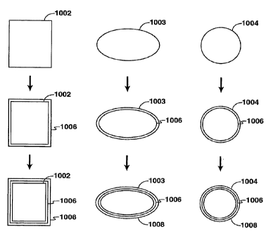
reservoir,
processing the hydrocarbons at a surface facility and/or other similar
operations.
Then, the process ends at block 516.
[0056] FIG. 6 is an exemplary flow chart of the selection and fabrication of
the compressible objects discussed in the flow chart of FIG. 5 in accordance
with
certain aspects of the present techniques. This flow char~ which is referred
to by
reference numeral 600, may be best understood by concurrently viewing FIGs. 1,
3A-3C, 4 and 5. In this flow chart 600, a process for selecting compressible
objects
to maintain the density of a drilling mud within the well between the PPG and
FG is
described. Beneficially, the use of compressible objects in the variable
density
drilling mud may enhance drilling operations by reducing the size of the
wellbore and
casing strings, and may provide access to greater depths.
[0057] The flow chart begins at block 602. At block 604, the FG and PPG for
a well are obtained. The FG and PPG may be obtained by receiving information
from the drilling location and/or performing calculation to estimate the FG
and PPG.
Then, a structure for each of the compressible objects is selected, as shown
in block
606. The selection of the structure for the compressible objects may include
using
finite element analysis (FEA) methods to match structures and geometries of
compressible objects to properties of the available materials, as described
above. At
block 608; wall materials for the compressible objects are selected. The
selection of
CA 02652406 2008-11-14
WO 2007/145733 PCT/US2007/010905
-20-
wall materials may include metals and/or metal alloy thin films formed
mechanically
or by depositional methods, polymers with or without micro and/or nanofiber re-
enforcement in a polymer matrix to achieve the specific properties of the wall
material (e.g., as defined by FEA analysis of the object compression). In
addition,
wall materials may include ex-foliated inorganic mineral as re-enforcement or
as a
barrier to gas permeability in a polymer matrix; metal and/or metal alloy thin
films
formed by depositional methods on polymer surfaces with or without chemical
modification of the polymer surface to form a structural wall or a barrier to
gas
permeation. The metal and/or metal alloy thin films may be deposited on
polymer
sheet prior to forming of the compressible object or on a pre-formed
compressible
polymer object. The metal layer may be formed on the inside or outside surface
of
the compressible objects or incorporated within a polymer wall or polymer
laminate
of the same or different polymers.
[0058] Surface treatments may be selected for the fabrication of the
compressible objects in block 610. The surface treatments may include physical
and/or chemical surface treatments to improve the continuity and adhesion of
metal
and/or metal alloy films on the surface of the polymer objects or to enhance
the
chemical and/or physical compatibility of the polymer or metallic exterior
wall of
compressible objects with the drilling fluid.
[0059] Once selected, the compressible objects are fabricated in block 612.
The fabrication of the compressible objects may include various
polymerizations,
depositions, surface treatments and other fabrication processes used to form
the
wall structures of the compressible object. For instance, the fabrication of
the wall
structures may include co-axial bubble blowing methods where the polymer is
the
structural wall; co-axial bubble blowing methods where the polymer is a
template for
the deposition of a metal or metal alloy structural wall; dispersion
polymerization
methods where the polymer is a template for the deposition of a metal or metal
alloy
structural wall; and/or interfacial polymerization methods where the polymer
is a
template for the deposition of a metal or metal alloy structural wall. The
fabrication
may include the deposition of a continuous metal or metal alloy layer on the
surface
of a compressible polymer object in either low or high pressure liquid
environments
using electro or electro-less plating methods; the deposition of a continuous
metal or
metal alloy layer on the surface of a compressible polymer object in high
pressure
CA 02652406 2008-11-14
WO 2007/145733 PCT/US2007/010905
-21 -
gas environments using ultraviolet chemical vapor deposition (UV-CVD) methods;
and/or the deposition of a continuous metal or metal alloy layer on the
surface of a
compressible hollow object under vacuum using physical and/or chemical
deposition
methods. The vacuum deposition methods may or may not include reducing the
internal pressure inside the compressible object prior to deposition. This may
be
accomplished for example, by first reducing the internal pressure of the
compressible
hollow object by cooling the pressurized compressible hollow object preferably
to a
temperature below which the gas inside the compressible hollow object may
condense. Further, fabrications may include molding or forming a flat
metalized
polymer sheet or film into portions of compressible objects and joining the
components using mechanical, chemical and/or thermal methods; forming a flat
polymer sheet or film into portions of the compressible object before
metallization
and joining the components using mechanical, chemical and/or thermal methods;
deposition of a metal or metal alloy on a polymer sheet with or without
chemical
and/or physical pre-treatment to improve adhesion and continuity and
subsequent
removal of the polymer template from the flat free standing metal or metal
alloy
sheet by physical, chemical and/or thermal methods resulting in the formation
of a
thin metallic sheet suitable for mechanical forming into components of
compressible
objects and subsequently joining the components by mechanical, thermal and/or
chemical methods; deposition of a metal or metal alloy on a polymer sheet pre-
formed into a template for free standing metal or metal alloy components of
the
compressible object and subsequent removal of the polymer template from the
metallic component by chemical, rriechanical and/or thermal methods and
subsequently joining the components by mechanical, thermal and/or chemical
methods.
[0060] At block 614, the compressible objects may be verified or tested. The
verification and testing may include cyclic compression tests to verify the
internal
pressure and to quantify the fatigue life of the compressible objects with or
without
micro-structural analysis of the structural wall and the joints if any. Then,
the
compressible objects may be stored, as shown in block 616. The storage of the
compressible objects may include placing the compressible objects in a storage
vessel. The compressible objects may be stored at ambient pressure or at a
pressure equal to or higher than the internal pressure of the compressible
objects to
facilitate packing of the compressible objects in the storage vessel.
Alternatively, the
CA 02652406 2008-11-14
WO 2007/145733 PCT/US2007/010905
-22-
compressible objects may be stored in a cold environment to reduce the
internal
pressure inside the compressible objects. The cold compressible objects may
then
be stored in a vessel at ambient pressure or at elevated pressure to
facilitate packing
of the compressible objects in the storage vessel and shipping the
compressible
objects to another location, such as the drilling location, for storage or
other similar
activities. The process ends at block 618.
[0061] Accordingly, based on the discussion above, the selection and use of
these compressible objects may involve different aspects that affect the
design of
the compressible objects. For instance, the nature of the transition to gas
compression controlled deformation is dependent on the mechanical properties
of
the shell or wall material and the evolution of those properties in repeated
compression cycles. As such, the compression of hollow objects results in a
different gradient of mud density above and below the depth defined by the
initial
internal pressure of the hollow objects. Because the use of compressible
objects
having different initial internal pressures may be beneficial to enhance or
extend
drilling operations, changing the volume fraction and distribution of initial
pressures
of compressible objects may achieve the desired result of maintaining the
effective
mud weight between the PPG and FG.
[0062] Further, the use of different gases may also influence the design of
the compressible objects. For instance, the hollow object may be filled with a
mixture of condensable and non-condensable gases. The addition of a
condensable
gas allows additional flexibility in tailoring the variation of drilling mud
density with
depth. At the temperature and pressure of the gas/liquid phase boundary, the
condensable gas liquefies with an increase in density and a corresponding
decrease
in volume. The decrease in internal volume of the hollow object results in a
step
increase in effective mud density at the depth and temperature corresponding
to the
phase transition. An additional benefit of using a gas mixture containing a
condensable gas is the finite internal volume occupied by the condensed gas at
depths once it has condensed because the compressibility of the condensed
liquid is
generally lower than that of the non-condensable gas. As a result, the
condensed
liquid volume may be used to set an upper limit on the deformation experienced
by
the wall of the hollow object. This may be utilized to control the fatigue
life of the
flexible objects as they cycle between the bottom of the welibore and the
surface.
CA 02652406 2008-11-14
WO 2007/145733 PCT/US2007/010905
-23-
[0063] Moreover, the operational use may influence the design of the
compressible objects. In particular, confining the volume change to a large
number
of small diameter compressible objects mixed into the drilling mud allows
tailoring of
the initial size and/or shape of the compressible objects to achieve a stable
composite mud fluid rheology within the vertical mud column of the wellbore.
To
create a usable variable density drilling mud, the initial properties of the
fluid phase
for a given compressible solid volume fraction is selected to suspend both the
rock
cuttings and the compressible objects in the wellbore annulus during non-
circulating
operations. In addition, the viscosity of the composite mud has to be
configured to
be pumped within the wellbore by mud and rig pumps within acceptable limits.
Also,
the use of different sized compressible objects may further enhance the
operational
use. These aspects and others are discussed further below.
Architecture of Compressible Objects
[0064] To determine the architecture of the compressible objects, as noted in
block 606 of FIG. 6, a finite element numerical modeling method may be
utilized.
The finite element numerical modeling method may include implicit methods
and/or
explicit methods. In these methods, the shell walls or elements may be
represented
by mesh size and shape tailored with higher resolution in regions of interest,
such as
regions of high stress and/or strain for compressible object construction. The
finite
element numerical model may be used to simulate the entire three dimensional
object or a segment of the object related to the three dimensional object by
symmetry. Further, the architecture of the compressible objects may be
influenced
by various criteria, such as the materials and use of the compressible
objects, which
are discussed in this and other portions of the application.
[0065] With regard to the use of the compressible objects, it should be noted
that the architecture of the compressible objects may facilitate periodic
removal of
the compressible objects from the re-circulating drilling mud. This may
facilitate
limiting potentially detrimental effects of the high volume fraction of
compressible
objects on the rheology of the drilling mud and/or facilitate the flow of the
compressible objects through the equipment, such as pumps, and orifices in the
flow
path. As such, the compressible objects may include structures having an
equivalent diameter in the range of about 0.1 mm (millimeter) to 5.0 mm. The
CA 02652406 2008-11-14
WO 2007/145733 PCT/US2007/010905
-24-
equivalent diameter is again defined as the diameter of a sphere of equal
volume as
the fully expanded compressible object at an external pressure of one
atmosphere.
In addition, the shape of the compressible objects may be adjusted to increase
the
packing density and reduce effects on fluid flow. For instance, a spherical or
elliptical object may provide the highest packing density and lowest effects
on the
fluid flow within the wellbore in comparison to pillow or rod shaped objects.
[0066] Another criterion for the architecture is the wall thickness. As noted
above, the wall thickness should be as thin as possible within the constraints
imposed by structural instabilities and the properties of existing materials
to
maximize the compression limit of the compressible object. However, the lower
limit
of the wall thickness is defined by the minimum thickness able to contain the
desired
internal gas pressure at an external pressure of about 1 atmosphere typically
encountered at the surface of the Earth.
[0067] To determine the optimal geometry of the compressible objects,
methods of finite element numerical modeling may be utilized. Finite element
numerical modeling is well known by those skilled in the art. These methods
may
include modeling the walls as shell elements of the compressible objects or as
a
mesh object with variable mesh size and shape. Certain regions of interest,
such as
regions of high stress and/or strain for the compressible object construction,
may be
tailored with higher resolution (i.e., smaller mesh size) to provide more
information in
these regions. Further, the model may be used to simulate the entire three
dimensional (3D) compressible object, a segment of the compressible object, or
a
portion of the compressible object that may be related to the 3D compressible
object
structure by symmetry.
[0068] As an example, one preferred method of analyzing and optimizing the
combinations of compressible object geometry, compressible object material
properties, internal gas properties, internal pressure and response of the
compressible object to changes in external temperature and/or pressure is to
construct a finite element model of either the entire compressible object or a
portion
of the compressible object (i.e., a hemisphere, due to symmetry). By using
software,
such as ABAQUST"" or any other suitable FEA analysis package, a finite element
numerical model may be constructed for the compressible objects. In this
model, an
CA 02652406 2008-11-14
WO 2007/145733 PCT/US2007/010905
-25-
expiicit method may be used to monitor for contact between the internal
surfaces of
the compressible objects during compression. To minimize oscillations during
external pressure modifications, the external pressure may initially be set
equal to
the internal pressure. Then, the external pressure may be slowly decreased
down to
ambient, which may be done over a period (e.g., 0.5 sec.) sufficient to
substantially
eliminate dynamic artifacts in the simulation. Depending on the flow behavior
of the
wall material and any occurrence of buckling, the amplitude and rate of
external
pressurization and depressurization may be adjusted to minimize oscillations.
Once
the finite element numerical model has been constructed, other analysis may be
performed. For instance, the compressible object may undergo a pressurization
cycle test. Then, an analysis of the data from the pressurization cycle test
may be
utilized to gain insight on the effect of compressible object geometry,
compressible
object dimensions and/or material properties. In addition, if the numerical
model is
constructed using shell elements, sudden changes in mesh geometry should be
avoided to reduce the potential for anomalies in local stress calculations.
[0069] As a specific example, the finite element numerical model of the
compressible object of FIGs. 3A-3C is discussed. In these embodiments, the
compressible object has the shape of an oblate ellipsoid. The initial aspect
ratio may
be in the range of 1 to 10, with a more preferred aspect ratio being in the
range of 2
to 5. The use of an internally pressurized oblate ellipsoid hollow
compressible object
with an initial aspect ratio greater than 1 has the advantage that at ambient
external
surface pressure, the ellipsoid object inflates and approaches an aspect ratio
of
about 1 depending on the internal pressure and material properties, as shown
in
FIG. 3B. If the ellipsoid object has an initial aspect ratio of 4:1, a uniform
NiTi alloy
wall thickness of 10 microns and an internal pressure of 1500 psig, the aspect
ratio
in the expanded state is about 1.22:1. As the external pressure increases, the
ellipsoid object tends to return to an initial state 300. In the initial state
300, the
aspect ratio of the ellipsoid object is that of the original design with
little elastic strain,
as shown in FIGs. 3A and 4. Then, as the pressure continues to increase, the
ellipsoid object is compressed further into a compressed state 312, as shown
in FIG.
3C.
CA 02652406 2008-11-14
WO 2007/145733 PCT/US2007/010905
-26-
Wal,l Material for Compressible Objects
[0070] In addition to the architecture, various materials may be utilized for
the
wall of the compressible objects based on the criteria discussed above, as
noted in
block 608 of FIG. 6. In particular, the shell or wall materials may be divided
into two
classes of commercially available materials, which are metal materials and
polymer
materials. The metal materials may include metals, metal alloys, and alloys
with
pseudo-elastic behavior (e.g., deformations associated with a reversible
stress
induced structural phase transformation). Further, the super-plastic behavior
of ultra
thin (i.e., < 500 Angstroms (A)) metal or metal alloy films may also be used
to make
a wider variety of metals and metal alloys (e.g., Aluminum (AI), Copper (Cu),
Nickel
Titanium (NiTi), etc.) suitable for application as a thin permeation barrier
in
conjunction with a non-metallic load bearing wall that satisfies the
mechanical
properties of the load bearing wall. Specifically, the metal materials may
include, but
are not limited to, binary or near binary NiTi, ternary alloys of NiTi with
iron and
chromium alloying additions, Magnesium-40Copper (Mg-40Cu) alloys, Beta-
Titanium-9.8Molybdenum-4Niobium-2Vanadium-3Aluminum ((3-Ti-9.8Mo-4Nb-2V-
3AI) alloys, metallic glasses and amorphous metals (e.g. Zirconium (Zr), Iron
(Fe)
and/or Magnesium (Mg) based alloys) and the like. The polymeric materials may
include polymers and polymer blends with or without reinforcement (e.g., micro
to
nano-fiber, nanotubes, exfoliated inorganic fillers with appropriate
orientation within
the polymer wall etc.). Examples of polymers with suitable properties include
but are
not limited to commercially available polyimide, such as Ubilex-R and Ubilex-
S.
[0071] Because each of these materials has specific properties, such as
tensile strength and recoverable elongation, the material utilized in the
walls of the
compressible objects is a factor in determining the thickness of the wall. The
determination may be based upon finite element numerical modeling, as noted
above, to evaluate different thicknesses of the shell or wall with different
materials.
For instance, if the load bearing wall material is a metal or metal alloy,
only metals
and metal alloys with sufficiently high elastic or pseudo-elastic behavior
should be
selected because deformations associated with a reversible stress induced
structural
phase transformation have to be recoverable for reuse of the compressible
objects.
As noted above, even these selected materials have to be combined with careful
design of the geometry of the exterior shell of the compressible object to
avoid strain
CA 02652406 2008-11-14
WO 2007/145733 PCT/US2007/010905
-27-
localization during compression and re-expansion. In particular, the geometry
and
material may be utilized for optimization of the wall thickness relative to
particle size;
variation of the bearing wall thickness and/or mechanical properties with
location on
the compressible objects' surface; and/or variation of the aspect ratio and
major
diameter of an oblate spheroid hollow compressible objects, etc. Accordingly,
these
various factors are considered in selecting a materiai for the compressible
objects.
[0072] As an example of the variation of wall thickness, the wall material may
be utilized to influence the compression ratios of the compressible object,
such as
the elliptical object discussed above in FIGs. 3A-3C. In FIG. 7, the FEA
calculations
provide various shapes that have different compression ratios within the
limits
defined by existing materials properties. The FEA calculations may provide
compressible objects having an aspect ratio between 2 to 5, with an equivalent-
diameter-to-wall-thickness ratio between 20 and 200, or more preferably
between 50
and 100. As shown in FIG. 7, a chart 700 of the effect of wall thickness is
shown for
maximum strain 702 of compressible objects against the equivalent diameter to
wall
thickness ratio 704 for various shapes, which are shown by curves 706-711,
generated from finite element numerical modeling. For sphere-shaped
compressible
objects, curve 706 has a compression ratio of 3.5, curve 707 has a compression
ratio of 3, and curve 708 has a compression ratio of 2. For the ellipse shaped
compressible objects, curve 709 has a compression ratio between 3.5 and 2,
curve
710 has a compression ratio between 3 and 2, and curve 711 has a compression
ratio of about 2. It is clear from the chart 700 that compressible objects
having an
aspect ratio greater than unity with a thinner wall (i.e., higher equivalent-
diameter-to-
wall-thickness ratio) are preferable because they provide higher compression
ratios
with correspondingly lower maximum strain. Also, it may be preferable to
maintain
the maximum strain below a specific value, of about 0.06 as defined by the
maximum allowable strain to achieve adequate fatigue life of the structural
wall.
Typically, a minimum fatigue life of at least 2000 to 3000 cycles is
desirable. Based
on this limitation, an ellipsoid object with an aspect ratio at 2 or more and
equivalent-
diameter-to-wall-thickness ratio greater than 65 provides a compressible
object that
is below the specific value, as shown on curve 711.
[0073] In addition to being a single material, the walls of the compressible
objects may include two or more layers. For instance, the layered composite
shell
CA 02652406 2008-11-14
WO 2007/145733 PCT/US2007/010905
-28-
may include a load bearing structural layer or wall and a gas permeation
barrier wall.
The load bearing wall may be a relatively thick wall having a thickness in the
range of
1 micron to 50 microns and a gas barrier wall may be a thin wall having a
thickness
in the range of less than or equal to 5 microns. For example, the load bearing
polymer wall, which may have a hollow interior or be deposited on a polymer
foam
template, may be utilized to provide the structure of the compressible object.
The
gas barrier wall, which may be internal or external to the load bearing wall
may be a
metal or metal alloy permeation barrier layer that contains the internal
pressure and
has a thickness below 500 Angstrom. Alternatively, the compressible objects
may
have a thin (i.e., < 5 micron) shell wall, which is either hollow or deposited
on a
polymer foam, with a relatively thick (i.e., 1 micron < wall thickness < 50
microns)
load bearing and barrier wall of metal or metal alloy layer that provides
structural
support and a barrier to gas permeation.
Selection of Surface Treatments for Compressible Objects
[0074] As discussed in block 610 of FIG. 6, various surface treatments may
be utilized for the compressible objects. The surface treatments may be
utilized to
improve the continuity and adhesion of polymer layers or metal and/or metal
alloy
films on the surface of the compressible objects, such as polymer objects..
Accordingly, the surface treatments may be utilized to enhance specific
properties,
such as compatibility with the base fluid and the permeability of the shell
layers to
maintain the internal pressure, which is discussed further below.
[0075] For internally pressurized compressible objects having a load bearing
wall of a polymer and/or an elastomer with or without reinforcement, a surface
treatment may be utilized to enhance the continuity of a metal and/or non-
metal film
deposited on the surface of the polymer to reduce the gas permeability of the
load
bearing wall. In general, elastomers, crystalline polymers and/or polymer
blends
have gas permeabilities too large to be useful for the fabrication of the
compressible
objects. Accordingly, in addition to the incorporation of exfoliated inorganic
fillers in
the polymer wall, the deposition of a continuous, thin (i.e., < 500 Angstrom)
low gas
permeability coating either on the surface of the wall or incorporated into a
layered
wall structure may be used. For example, the coating may be a thin metal,
metal
alloy or inorganic gas permeation barrier, which is applied through a variety
of
CA 02652406 2008-11-14
WO 2007/145733 PCT/US2007/010905
- 29 -
physical and/or chemical treatments to the exterior of the surface wall of the
compressible object. In particular, the deposition coating may be less than
500 A in
thickness and include Al, NiTi, or any other suitable material. Surface
treatments to
enhance the uniformity and/or continuity of these permeation reducing layers
may
include: (1) Anionic functionalization of the surface e.g., sulfonation,
carboxylation,
i.e., acid formation, as well as other anionic functionalizaton methodologies
and
chemistries used by those well-versed in the state of the art. (2) Cationic
quaternization functionalization chemistries e.g., sulfonium salts,
phosphonium salts,
ammonium salts, used by those well-versed in the state of the art. (3)
Zwitterionic
ionic functionality and amphoteric functionality practiced by those well-
versed in the
state of the art. (4) Maleation functionalization and the associated reactions
known
by those well-versed in the state of the art. (5) Controlled oxidation e.g.,
peroxides,
high temperature oxygen plasma etching, ozone, and the like. (6) Chemical
vapor
deposition methodologies and associated chemistries. (7) Corona discharge
approaches to surface functionalization used by those well-versed in the state
of the
art.
[0076] A wide variety of methods are available for deposition of metal and/or
inorganic barrier coatings. One of the factors that may influence the
selection of
deposition method is the internal pressure of the compressible object. For
instance,
if little or no initial internal gas pressure is contained within the
compressible objects,
then a low permeability metal, metal alloy or inorganic coating may be
utilized
through various low pressure physical and chemical deposition methods to
uniformly
coat the non-planar geometry of the compressible objects. If the compressible
object's internal pressure and the wall permeability is such that the low
pressure
environment (i.e., typically < 1 x10"3 mm of Hg) required for iow pressure
physical and
chemical deposition methods is not maintainable, deposition methods compatible
with the internal gas pressure and relatively high wall gas permeability may
be used.
In this example, the compressible objects may be maintained in a high pressure
gas
or liquid environment to prevent loss of internal pressure through the wall of
the
compressible object during storage and coating. For a high pressure liquid
environment, the coating of the wall surface may be accomplished, for example,
by
electro or electro-less plating using methods familiar to those skilled in the
art. For
the high pressure gas environment, the coating of the wall surface may be
CA 02652406 2008-11-14
WO 2007/145733 PCT/US2007/010905
-30-
accomplished by, for example, chemical vapor deposition (CVD) or ultraviolet
chemical vapor deposition (UV-CVD) deposition.
[0077] Alternatively, the internal gas pressure inside the compressible
objects may be reduced to a level that allows application of a range of
commercial
low pressure physical and chemical deposition methods available for an un-
pressurized object or polymer sheet. In this example, a gas, which may be
condensed by lowering the temperature of the compressible object, may be
utilized
for the internal pressurization of the compressible object. For instance, if
the gas
internal to the compressible object is oxygen (0) at a pressure of 10 mPa,
subsequent cooling the compressible objects to the temperature of liquid
nitrogen
(LN2) at atmospheric pressure may reduce the internal pressure to less than or
equal
to 1 x 10"3mrn of Hg.
[0078] Similar considerations for a hollow polymer load bearing wall may be
applied for internally pressurized compressible objects having a load bearing
wall of
polymer and/or elastomer foam and gas barrier wall of a metal and/or non-metal
permeation barrier, or for a polymer and/or elastomer ultra thin hollow shell
or a
polymer and/or elastomer foam used as a template for deposition of a load
bearing
metal and/or metal alloy wall, as noted above. In the latter example, an ultra
thin
polymer shell or polymer foam may, be utilized as a template for the
deposition of a
relatively thick metal and/or metal alloy load bearing wall. The metal or
metal alloy
load bearing wall in this example may have a thickness from about 5 microns to
50
microns. The ultra thin polymer shell or polymer foam may include any polymer
and/or elastomer with or without reinforcement and surface treatments to
enhance
the uniformity and continuity of the metal and/or metal alloy load bearing
wall. In this
example, the thickness of the ultra thin polymer shell and/or the mechanical
strength
of the foam need only be sufficient to maintain the desired shape of the
particle
during the deposition process.
Fabrication of Compressible Objects
[0079] As discussed in block 612 of FIG. 6, once the structure and wall
materials are selected for compressible objects, various fabrication
techniques may
be utilized to create the compressible objects. These fabrication techniques
may
include various processes, such as patterning, deposition, thermo-mechanical
CA 02652406 2008-11-14
WO 2007/145733 PCT/US2007/010905
-31-
processing and other similar fabrication processes. The patterning processes,
which
are processes that shape material into another form, such as compressible
objects,
may include chemical etching, mechanical etching and the like. The etching
processes are processes that remove material from a base material. The
deposition
processes, which are processes that coat or transfer a material -onto another
material, may include physical vapor deposition, chemical vapor deposition,
electrochemical and/or electro-less deposition, metallization, sputtering,
evaporation,
molecular beam epitaxy and the like. The thermo-mechanical processes, which
are
processes that form or change a materials shape and microstructure, may
include
cold rolling, hot rolling, swaging, drawing, cutting, tempering, solution
annealing and
the like.
[0080] The fabrication of compressible objects may use various techniques
that are combined to provide desirable properties of the compressible objects,
as
described above. The fabrication route of the compressible objects may be
determined based on certain desirable properties of the compressible objects.
For
example, low gas permeability, object flexibility, mechanical integrity, low
cost,
relative ease of object fabrication, commercial availability of materials,
and/or
environmentally acceptable materials properties are some of the properties
that may
be considered. Other properties may include, desirable range of compressible
object sizes, size distributions, and aspect ratios, potential surface
functionalization
approaches to enhance polymer/metal adhesion, ability to incorporate "excess"
blowing agent(s) to produce a hollow object containing a high pressure gas
interior
(e.g., the use blowing agent to internally pressurize hollow objects, fill
with high
pressure gas and the like) among other features.
[0081] Accordingly, the fabrication processes may be configured to create
compressible objects that are gas filled polymer objects including internal
structures
being either hollow or at least partially filled with foam. For instance,
F1Gs. 8A-8B
are exemplary embodiments of fabrication processes that create compressible
objects having hollow interiors. Similarly, FIGs. 9, 10 and 11A-11B are
embodiments
of fabrication processes that create compressible objects having foam
interiors or
based upon foam templates.
CA 02652406 2008-11-14
WO 2007/145733 PCT/US2007/010905
-32-
A. Fabrication of Compressible Objects as Hollow Objects
[0082] The fabrication processes described below relate to the fabrication of
compressible objects that are formed as hollow objects, which may or may not
be
gas filled. These fabrication processes may be utilized to form compressible
objects
that each has a shell enclosing an interior region, each of the compressible
object
has (a) an internal pressure (i) greater than about 200 psi at atmospheric
pressure,
500 psi at atmospheric pressure 1500 psi at atmospheric pressure or 2000 psi
at
atmospheric pressure and/or having a shell that encloses an interior region
and (ii)
selected for a predetermined external pressure, wherein external pressures
that
exceed the internal pressure reduce the volume of the compressible object; (b)
the
shell configured to experience less strain when the external pressure is about
equal
to the internal pressure than when the external pressure is greater than the
internal
pressure or less than the internal pressure or the shell that experiences less
strain
when the external pressure is about equal to the internal pressure than when
the
external pressure is above or below a predetermined compression interval of
the
compressible object; and/or (c) the shell is at least partially filled with a
foam. While
a variety of fabrication processes are described, FIGs. 8A-8B are exemplary
embodiments of fabrication processes that create compressible objects having
hollow interiors.
[0083] FIGs. 8A-8B are exemplary embodiments of fabrication processes
utilized in the flow chart of FIG. 6 in accordance with certain aspects of the
present
techniques. In FIG. 8A, an exemplary embodiment of an apparatus for creating
compressible objects in accordance with the present techniques is-shown. In
this
embodiment 800, compressible objects, such as hollow polymer shells or polymer
foam structures, may be fabricated in a pressurized environment formed by a
pressurized chamber 802. For exemplary purposes, the compressible objects are
shown as hollow polymer shells 804 with a gas interior 806, but may include
polymer
foam structures and other compressible objects discussed above.
[0084] In this fabrication process example, a coaxial bubble blowing orifice
808 at the end of the center tube 810 is enclosed in a coaxial tube 812 in a
pressurized chamber 802. Sufficient differential pressure is independently
applied
within the annulus formed between the center tube 810 and the coaxial tube 812
and
CA 02652406 2008-11-14
WO 2007/145733 PCT/US2007/010905
33-
within the center tube 810 of the orifice to shape the polymer material 814
into hollow
polymer shells 816 that are filled with gas 818 from the center tube 810. In
this
manner, a gas 818 filled polymer bubble 820 is formed and subsequently
detaches
from the coaxial bubble blowing orifice 808. The pressurized chamber 802 may
be
filled with gas or liquid or a combination thereof and the separation in the
case of
bubble formation may be caused by surface tension, gravity, buoyancy, fluid
flow or
any combination thereof. Once the polymer bubble 820 detaches, the polymer
bubble 820 may be dropped into a crosslinking bath 822 within a bath vessel
824
that promotes crosslinking of the polymer wall. The chemical nature of the
crosslinking bath may be determined by the specific polymer chosen for the
wall
material and well known to those skilled in the art of polymer synthesis.
Following
the hardening bath, the hollow polymer shells 804 with a gas interior 806 is
formed
and may then be removed by transfer to a pressure interlock chamber (not
shown)
where the crosslinking fluid is separated from the pressurized compressible
objects
and the compressible objects are transferred to a container for storage.
[0085] Further, during or after polymerization and/or separation of the hollow
polymer shells 804, the pressure surrounding the hollow polymer shells 804 may
be
lowered to expand the hollow polymer shells 804 into its final size and shape
in the
expanded state. This expanded state may be predetermined by wall thickness,
material mechanical properties, object architecture and internal pressure
before,
during or after cooling of the walls. If the polymer wall.is the load bearing
member,
expansion of the diameter following synthesis may be used to alter the
mechanical
properties of the polymer wall. For example, by strain re-orientation of the
polymer
chains and/or re-orientation of the reinforcement in the polymer wall of the
hollow
polymer shells 804.
[0086] Specific adjustments may be incorporated for the fabrication process
based on the materials utilized. For instance, if the polymer material 814 is
a
polymer melt with or without reinforcement, the orifice 808 may be heated to
reduce
the melt viscosity to achieve the desired flow properties of the polymer melt.
Also, if
the polymer material 814 is a polymer monomer or a mixture of monomers with or
without reinforcement and with or without an initiator, the polymerization of
the walls
of the polymer bubble 820 after separation from the orifice 808 may be
accomplished
by a variety of processes, such as ultra violet polymerization, free radical
CA 02652406 2008-11-14
WO 2007/145733 PCT/US2007/010905
-34-
polymerization, thermo-chemical polymerization, etc., which are familiar to
those
skilled in the area of polymer synthesis.
[0087] In FIG. 8B, another exemplary embodiment 830 of an apparatus for
creating compressible objects in accordance with the present techniques is
shown.
In this embodiment 830, compressible objects, such as hollow polymer shells or
polymer foam structures, may be fabricated in a pressurized environment formed
in
a pressurized chamber 832. The pressurized chamber 832 is divided into a lower
chamber 838 having a gas inlet 840 and an upper chamber 842 having a fluid
inlet
844 and a fluid outlet 846. For exemplary purposes, the compressible objects
are
shown as hollow polymer shells 834 with a gas interior 836, but may include
polymer
foam structures and other compressible objects discussed above.
[0088] In this fabrication process example, a thin film 848 of a suitable
polymer melt or polymer precursor may be formed on a plate 850 perforated by a
large number of orifices or holes 852. The size and spacing of the holes 852
may be
arranged to cause the continuous formation of gas filled bubbles 854, which
have a
hollow polymer shell 834 with a gas interior 836, that separate and float off
the plate
850 and into a pressurized fluid filling the upper chamber 842 when the plate
850 is
pressurized from below at a desired differential pressure between the upper
and
lower chambers 838 and 842. It should be noted that a variety of alternative
geometries of holes may be utilized to form internally pressurized hollow
compressible objects from a thin film of polymer precursor and/or polymer
melt. The
gas filled bubbles may exit the upper chamber 842 through the fluid outlet 846
and
may be separated from the fluid by density difference and subsequently
transferred
to a container for storage.
[0089] As an alternative exemplary method for creating compressible
objects, metal, metal alloy and/or polymer tubes may be utilized to form the
compressible objects. In this fabrication process, compressible objects are
formed
from a tube material by cutting the tube material into desired lengths and
closing the
ends of the tube material using mechanical, chemical or thermal methods. The
internal pressure of the resulting compressible objects, which may be formed
in the
shape of a pillow, sphere, oblate spheroid, ellipsoid of revolution or any
other
desirable shape may be controlled by closing the cut ends of the tube and
forming
CA 02652406 2008-11-14
WO 2007/145733 PCT/US2007/010905
-35-
the desired shape in a controlled pressure environment. The pressurized
environment may be a pressurized chamber, which is similar to the pressurized
chambers discussed above. In addition, the compressible objects may be formed
either before or after metallization of the polymer wall of the tube material
from a
polymer and/or elastomer tube with or without reinforcement.
[0090] As another alternative example method for creating compressible
objects, preformed sheets may be utilized to form the compressible objects. In
this
method, mechanical, thermal or chemical joining of preformed sheets may be
utilized
to fabricate compressible objects. The preformed sheets may include a layered
composite structure, which may include two embodiments. One embodiment may be
a relatively thick structural load bearing polymer wall combined with a
relatively thin
continuous metal, metal alloy and/or non-metal permeation barrier layer. In
particular, the structural load bearing polymer wall may have a wall thickness
between about 5 micron and 50 microns, while the continuous metal or metal
alloy
permeation barrier layer may have a wall thickness that is less than about 500
Angstrom. The second embodiment being a thin polymer sheet as a template for
the
deposition of a relatively thick metal or metal alloy layer that serves as
both a
structural wall and a barrier to gas permeation. For instance, the thin
polymer sheet
may be less than about 5 micron, while the metal or metal alloy layer may have
a
wall thickness between about 5 micron and 50 microns. Any combination of
layered
or multiply layered embodiments with polymer thickness and metal or metal
alloy
thickness within these limits may be utilized for other embodiments.
[0091] To fabricate these compressible objects, the one or more layered pre-
formed sheets may be fabricated flat and subsequently molded into a pre-formed
object component using any of a variety of polymer sheet and/or film forming
methods familiar to those practiced in the art. Examples include metalized
polymer
sheet for food packaging, metalized Mylar sheet for party balloons, decorative
metal
coatings on polymers films and metalized polyimide film for aerospace thermal
barriers. If the pre-formed object components are to be joined to form the
compressible objects, the joining of the preformed object components may be
accomplished by a variety of methods familiar to those practiced in the art of
polymer
film joining. Examples include but are not limited to, thermal bonding,
adhesive
bonding, mechanical joining and the like.
CA 02652406 2008-11-14
WO 2007/145733 PCT/US2007/010905
-36-
[0092] In this exemplary fabrication method, the metal or metal alloy layer
may be formed on the interior or exterior of the compressible object using the
same
range of physical and/or chemical methods described above and known in the
field
for deposition of the metal, metal alloy and/or non-metal coatings. For
instance, the
metal or metal alloy layer may be applied to the exterior and/or the interior
surface in
a manner similar to the methods described for deposition on co-axially blown
bubbles or bubbles formed by dispersion polymerization above. The coated
polymer
wall may then be thermo-mechanically molded into the pre-form to have the
metal or
metal alloy layer on the interior surface, the exterior surface or both. In
this
embodiment, the reinforcement, surface treatment for improved continuity and
adhesion and the reorientation of the reinforcement and/or the polymer chains
by
mechanical stress may also apply to the fabrication of the flat preformed
sheets and
may be performed in a manner similar to the co-axial blowing or dispersion
polymerization.
[0093] As an additional fabrication technique, the method of composite sheet
fabrication outlined above may also be used to fabricate free standing
relatively thick
metal and metal alloy sheet suitable for mechanical forming into the
components of
compressible or collapsible objects or particles. This approach to the
fabrication of
free standing metal or metal alloy sheet is particularly useful when thin
metallic sheet
is difficult to fabricate by conventional thermo-mechanical methods used in
the
fabrication of metal sheet. In particular, the metal and metal alloy sheet may
have a
thickness between about 5 micron and 50 micron. To form a free standing
metallic
sheet, the polymer template may be removed from the thin metallic sheet
following
deposition of the metal or metal alloy before or after any additional thermo-
mechanical treatment required to consolidate the deposited thin sheet. Removal
of
the polymer template may be accomplished by a variety of mechanical, chemical
and/or thermal methods known to those of ordinary skill in the art.
Alternatively, the
polymer template sheet may be pre-formed in the components of the compressible
objects prior to deposition of the metal or metal alloy thin film to form a
free standing
metal or metal alloy pre-form.
[0094] As another fabrication technique, hollow compressible objects may be
formed by physical and/or chemical vapor deposition (as described above) of
the
chemical constituents of a thermoset polymer onto thermally depolymerizable
hollow
CA 02652406 2008-11-14
WO 2007/145733 PCT/US2007/010905
-37-
polymer template or polymer foam. Subsequent to deposition, the themoset
polymer
constituents may be partially reacted together by raising the temperature to
form a
self supporting themoset polymer preform layer on the surface of the
depolymerizable hollow polymer shell or polymer foam template. Subsequent to
the
formation of the self supporting thermoset polymer preform layer, the
temperature
may be further increased to depolymerize the hollow and/or foam template and
the
depolymerization products removed from the resulting hollow self supporting
object
by diffusion through the thermoset preform wall. Finally, the partially cured
self
supporting hollow preform thermost objects may be placed into a high pressure
vessel and the pressure inside the hollow objects equilibrated by diffusion
through
the thermoset preform wall with a high gas pressure established inside the
vessel.
Subsequently, the temperature may be raised further in the high pressure gas
environment to fully cure the thermoset polymer in order to lower the gas
permeability of the wall and to achieve the optimum mechanical properties of
the wall
material. As before, metallization of the exterior surface of the fully cured
and
pressurized hollow thermoset polymer shell may be accomplished by the methods
described above for the coaxially blown pressurized hollow polymer shells.
[0095] Further, as another embodiment, the compressible objects may be
mechanically conditioned during fabrication to strengthen the structural wall
of the
compressible objects by reorientation of the micro and/or nano-fiber
reinforcement
and/or the polymer chains including the wall material by mechanical stresses.
This
mechanical conditioning may include, but is not limited to, expansion of the
compressible object to its final size and shape.
B. Fabrication of Compressible Objects Using a Foam Template
[0096] In addition to the fabrication of hollow objects, fabrication processes
may utilize a foam template to create a specific shape in the fabrication of
the
compressible objects. These fabrication processes may form compressible
objects
having a shell that encloses an internal region and (a) an internal pressure
(i) greater
than about 200 psi at atmospheric pressure, 500 psi at atmospheric pressure,
1500
psi at atmospheric pressure or 2000 psi at atmospheric pressure and (ii)
selected for
a predetermined external pressure, wherein external pressures that exceed the
internal pressure reduce the volume of the compressible object; (b) the shell
at least
CA 02652406 2008-11-14
WO 2007/145733 PCT/US2007/010905
-38-
partially filled with a foam; and/or (c) wherein the shell is configured to
experience or
experiences less strain when the external pressure is about equal to the
internal
pressure than when the external pressure is greater than the internal pressure
or
less than the internal pressure or wherein the shell experiences less strain
when the
external pressure is about equal to the internal pressure than when the
external
pressure is above or below a predetermined compression interval of the
compressible object. The foam template may include homopolymers, polymer
blends, copolymers, interpenetrating networks, block copolymers, thermosets,
thermoplastics, amorphous polymers, crystalline polymers, chemically
crosslinked
copolymers, thermoplastic elastomers, rubbers, liquid crystal polymers, and
the like.
The foam template may be formed into different predetermined shapes, such as,
but
not limited to, a sphere, rod, lamelia, oblate or prolate spheroids,
ellipsoids of
revolution and/or any combination of these geometries. Further, the foam
templates
used in the fabrication of the compressible objects, such as rods, lamellae
and the
like may be structured to internally contain a wide range of pore structure
(i.e.,
closed and/or open pores), pore wall thickness, and pore density. These
various
constructions may be useful for producing hollow objects spanning a wide range
of
mechanical performance.
[0097] Foam pre-forms may be produced via molding procedures, cutting
procedures, and coating procedures, which may be similar to techniques related
to
using foams for forming insulation and/or packaging. The cutting procedures
may
involve cutting slabstock foam into various shapes and sizes. The molding
techniques, which may include extrusion, blow molding, compression molding and
the like, may involve molding the foam into a desired intricate shape, which
may
reduce or eliminate labor-intensive cutting and waste produced from that
technique.
In addition, molding techniques may produce foams having multiple zones of
hardness and with filler reinforcements. The coating methods described
previously
may also be applied to coating of the foam pre-form, which methods may include
electroplating, electroless plating, physical vapor deposition, chemical vapor
deposition, ultra-violet chemical vapor deposition, and the like, and may be
used to
form a relatively thin metal or metal alloy layer over the foam template. The
coating
of metal or metal alloy layer in this embodiment is utilized to enhance the
impermeability of the compressible objects, which may include a gas (or
mixture of
gases) under pressure. Alternatively, the polymer template may be used for the
CA 02652406 2008-11-14
WO 2007/145733 PCT/US2007/010905
- 39 -
deposition of a relatively thick metal and/or metal alloy load bearing wall
using a
molded or mechanically shaped internally pressurized or un-pressurized polymer
foam. The metal load bearing wall may have a wall thickness of about 5 micron
to
50 micron and an internal pressure above about 200 psi at atmospheric pressure
or
greater depending on the desired application.
[0098] As a first embodiment, blowing agents may be utilized to form the
foam template for the compressible objects. Typically, the use of physical
blowing
agents results in closed-cell foam template, which may be formed from various
materials. For instance, polyurethane (PU), polystyrene (PS) and polyvinyl
chloride
(PVC) are materials utilized in manufacturing polymer foams. Typically, PU
foams
are prepared by in situ generation of carbon dioxide (CO2), while PS and PVC
foams
are prepared using physical blowing agents like nitrogen (N2) and COz. The use
of
physical blowing agents reduces any contaminating solvents from hindering the
process. The use of COZ and N2 has a number of benefits, such as chemical
inertness, non-combustibility, natural occurrence, low cost, ready
availability,
environmental acceptability (no ozone depletion) and low human toxicity.
[0099] Each of the polymer foaming techniques that use physical blowing
agents rely on the similar principles. These principles are (1) saturation of
the
polymer with a gaseous penetrant (blowing agent) at high pressure; (2)
quenching of
the polymer/gas mixture into a super-saturated stage either by reduced
pressure or
increased temperature; and (3) nucleation and growth of gas cells dispersed
throughout the polymer matrix. Upon quenching of the polymer/gas mixture, the
solubility of the gas in the polymer template decreases, which results in
clustering of
gas molecules in the form of nuclei. As gas diffuses into the forming cells,
the free
energy of polymer template is lowered. The cell nucleation process governs the
cell
morphology of the polymer material and properties of the polymer material.
Also,
this process may occur homogeneously throughout the material or
heterogeneously
at high-energy regions, such as phase boundaries. In the high energy regions,
the
free energy to nucleate a stable void is less compared to homogeneous
nucleation.
As a result, preferential nucleation of voids occurs at the interface.
[00100] In semicrystalline polymers, the crystalline domains may serve as
heterogeneous nucleation points to generate gas bubbles. In general, cell
growth is
CA 02652406 2008-11-14
WO 2007/145733 PCT/US2007/010905
-40-
controlled by the time that the gas has to diffuse into the cells before the
quenching,
the temperature of the fabrication process, the degree of supersaturation, the
rate of
gas diffusion into the cells, the hydrostatic pressure or stress applied to
the polymer
matrix, the interfacial energy and the visco-elastic properties of the
polymer/gas
mixture. The stiffness of the polymer template is typically controlled by the
foaming=
temperature. It should be noted that a reduction in average cell size
generally
increases stiffness. The work necessary to expand the gas cell has to overcome
the
additional stress resulting from the increased stiffness. By increasing the
saturation
pressure, the free energy barrier for the formation of stable nuclei is
decreased and
additional nucleation sites are formed due to matrix swelling, free volume
changes,
and/or the formation of crystalline interfaces. This results in an increased
cell density
and consequently a decreased average cell diameter. Semicrystalline. polymers
exhibit considerably higher cell densities than amorphous polymers, which are
attributed to the contribution of heterogeneous nucleation at the
amorp hous/crystal line interfacial regions. Because the gas does not dissolve
in
crystallites, the nucleation is nonhomogeneous, which makes it difficult to
control the
cellular structure of semi-crystalline foams. As a result, polymers with a low
crystallinity afford foams with an almost uniform structure. As the
crystallinity of the
polymer is increased, less desirable non-uniform foams with irregular cell
sizes are
obtained.
[00101] Because the foaming methods using physical blowing agents is
versatile, this technique may be used to fabricate closed-cell polymer foam
templates for the compressible objects. For instance, amorphous as well as
semi-
crystalline polymers may be processed within a range of temperatures close to
the
glass transition temperature (Tg) up to temperatures just below the melting
point of
the material. For exemplary purposes, a fabrication process for forming foam
templates and coating of the foam templates is discussed below in FIG. 9.
[00102] FIG. 9. is an exemplary flow chart for fabricating the compressible
objects in FIG. 6 that use a foam template in accordance with certain aspects
of the
present techniques. This flow chart, which is referred to by reference numeral
900,
may be best understood by concurrently viewing FIGs. 1 and 6. In this flow
chart
900, a process for fabricating compressible objects having a foam interior is
described.
CA 02652406 2008-11-14
WO 2007/145733 PCT/US2007/010905
-41 -
[00103] The flow chart begins at block 902. At block 904, the foam may be
fabricated. The foam may be formed from the various processes, which are
discussed above. The foam may include polymeric materials, such as moderate to
highly crosslinked elastomers with and without reinforcement; such as macro,
meso
to nano-fibers, nanotubes, exfoliated inorganic fillers (e.g. clays); and
polymeric
blends with and without reinforcement, such as macro, meso to nano-fibers,
nanotubes, exfoliated inorganic fillers (e.g. clays) and the like. At block
906, the
foam may be formed into foam templates. The foam templates may include the
various shapes, such as cubes, rectangles, rods, squares and other regular or
irregular shapes, which are discussed above. To form the foam templates, the
foam
or polymeric material may be shaped into different geometries and sizes by
cutting
or other suitable processes. Then, at block 908, the shaped foam templates may
be
coated with a material. The material may include a thin metal or non-metal
coating
to reduce gas permeability that is applied through any suitable deposition
technique
as discussed above. The coatings may include a wide range of compositions
including pure metals, metal alloys and/or layers of different metals or metal
alloys
either alone or in combination with non-metallic layers among others. At block
910,
the coated foam templates may be further treated by surface treatments to
enhance
the adhesion with and promote the continuity of these coatings with the
surface of
the polymer foam template. These surface treatments may be similar to the
surface
treatments discussed above. The process ends at block 912.
[00104] The coating of these different shaped foam templates is shown in
FIG. 10. In FIG. 10, various foam templates, such as a pillow object 1002, an
elliptical object 1003 and a spherical object 1004 are shown. These foam
template
objects 1002-1004 are formed into various shapes as discussed in block 906.
Then,
the foam template objects 1002-1004 may be coated by a metal layer 1006, as
discussed in block 908. In particular, the foam template objects 1002-1004 may
be
coated with a thin metal coating (e.g., copper) through an electroless plating
technique. Once coated, the foam template objects 1002-1004 may be further
coated by a surface treatment layer 1008, as discussed in block 910.
[00105] As a specific example of this fabrication process, a first foam
template
and a second foam template are described. The first foam template may be an
air
filled foam microcapsule having cells of about 1000 pm (micro-meter) to 1500
pm in
CA 02652406 2008-11-14
WO 2007/145733 PCT/US2007/010905
-42-
diameter, while the second foam template may be an air filled foam
microcapsule
having cells of about 250 pm to 500 pm in diameter. These foam templates may
be
cut into different geometries and sizes, as noted above. Then, the shaped foam
templates may be subsequently coated with a thin metal coating (e.g., copper)
through an electroless plating technique. The metal coatings may include a
wide
range of compositions including pure metals, blends of metals, alloys, shaped
memory alloys among others.
[00106] Further, it should be noted that the surface treatments may be
adjusted for different foam templates. For instance, if polystyrene is the
foam
template, it is highly non-polar and chemically reactive polymer. The degree
of
functionalization, i.e., sulfonation, may be controlled via a number of
parameters
such as: solvent, sulfuric acid concentration, reaction temperature, reaction
time,
catalyst, and catalyst concentration. As such, it should be noted that the
surface
functionalization chemistry and subsequent procedures may be modified to
accommodate the surface chemistry and structure of the material, such as
nylon,
polyesters, polyurethanes among many other polymeric materials. The surface
functionalization and etching may include acid treatment, base treatment,
oxidation,
nitration, sulfonation, phosphonation among many other chemistries. See J.
March,
"Advanced Organic Chemistry: Reactions, Mechanisms, and Structure", Third Ed.,
John Wiley & Sons, New York (1985), sections relating to sulfonation, mild
oxidation,
esterification, carboxylation, free radical addition reactions, free radical
graphing
reactions, and quaternization, and the like.
[00107] As a first specific example, foam templates may be coated uniformly
by a process, such as electroless copper plating, to form the rod-like foamed
object.
The foam template may be an air-filled foam microcapsule having cells of about
1000 Nm (micro-meter) to 1500 pm in diameter. If this foam template is
polystyrene,
the fabrication process may include fuctionalization of the polystyrene rod by
exposure to a 30% solution of H2SO4 for a period of 21 hours. The surface of
the
functionalized polymer can be activated using a tin-palladium (Sn-Pd)
activation
process, otherwise known as seeding. This seeding process is familiar to those
skilled in the art. The process involves successive immersions of the
polystyrene rod
in acidic tin-chloride (SnCI2) (0.01M) followed by acidic palladium-chloride
(PdCIZ)
(0.01 M) solution with rinsing in distilled water between the baths. A 0.01 M
Hydrogen-
CA 02652406 2008-11-14
WO 2007/145733 PCT/US2007/010905
-43-
Chloride (HCI) is used after the PdClz to remove the remaining Sn compounds
from
the surface. Each of the baths are performed at room temperature. See B.
Ceylan
Akis, "Preparation of Pd-Ag/PSS Composite Membranes for Hydrogen Separations",
A Thesis, Worcester Polytechnic Institute, (May 2004). The functionalized, Pd
seeded polystyrene rod can be placed in a bath flowing at the rate of 73
cc/min
(cubic centimeters/minute) containing a copper (Cu) plating solution of CuSO4-
5H20,
ethylenediaminetetraacetic acid disodium salt dihydrate, NaOH,
ethylenediamine,
and triethanolamine activated with formic acid. See Y. Lin and S. Yen, Applied
Surface Science, 178, 116 (2001); W. Lin, H. Chang, Surface and Coatings
Technology, 107, 48 (1998); Shu et. al., lnd. Eng. Chem. Res. 36, 1632 (1997);
Hanna et al. Materials Letters, 58, 104 (2003). Cu can be plated onto the
functionalized, Pd seeded polystyrene rod at 40 C over a period of 90 minutes
followed by a distilled water wash. The majority of the surface can be coated
with Cu
having a thickness that ranges from 0.3 - 0.6 m.
[00108] Alternatively, if the foam template is an air-filled foam microcapsule
having cells of about 250 Nm to 500 pm in diameter and a spherical shape, the
fabrication process may include fuctionalization and Pd seeding of the
polystyrene
sphere, as described above. Using the same Cu plating solution and flow rate,
the
functionalized Pd seeded polystyrene sphere can be plated at 40 C for a period
of
minutes followed by a distilled water wash. As a result, the surface can be
coated
with a 0.1-0.2 m thick Cu film that follows the contours of the foam surface.
[00109] As another example, the fabrication process for a solid Nylon 6/6 ball
having the diameter of 1/8 inch may include functionalizing and Pd seeding the
solid
ball as described above using 0.01 M HCI for 10 minutes for the
fuctionalization
process. Also, the Nylon ball can be reacted in the flowing solution at 40 C
for 4
hours 5 minutes followed by a distilled water wash, which may be the same Cu
plating solution with activator discussed above. The resulting Cu plated film
can be
10-25 m thick over the Nylon ball.
[00110] As another exemplary fabrication technique, a hollow gas-filled
metallic shell may be fabricated by utilizing the Fraunhofer method for
producing
hollow metallic objects, as shown in FIG. 11A. See, for example, O. Andersen,
U. Waag, L. Schneider, G. Stephani, B. Kieback, "Novel Metallic Hollow Sphere
CA 02652406 2008-11-14
WO 2007/145733 PCT/US2007/010905
- 44 -
Structures", Advanced Engineering Materials 2000, vol 2, (Apr 2000), pp. 192-
195.
In this embodiment 1100, foam templates 1102, which may be Styrofoam templates
or any of the polymer foam templates described above, may be coated with a
metallic material 1104, which may comprise a metal or metal alloy powder and
binder. The coating of the foam templates 1102 by metallic material and binder
1104
may be accomplished by fluidized bed coating methods in a vessel 1106. The
resulting polymer foam templates coated with a metal or metal alloy powder and
binder layer 1108 may then be subjected to a furnace 1110 for annealing. In
the
furnace, the polymer foam template may be thermally decomposed or reacted to
volatile reaction products which are removed by diffusion through the
partially
sintered metal or metal alloy wall. Subsequently, the temperature may be
raised to
drive off the remaining binder and the metal material is sintered to obtain a
dense
metal or metal alloy shell. The resulting compressible objects 1112 may be
utilized
as part of the variable density drilling mud once it has cooled.
[00111] An alternative fabrication method is described in FIG. 11B. In FIG.
11 B, either regular or irregularly-shaped metal or metal alloy hollow objects
may be
fabricated by forming a metal or metal alloy layer such as a nickel layer on a
foam
template by deposition from the gas phase onto a disposable foam template. In
this
embodiment 1120, a foam template 1122, which may be closed-cell polymer foam
template, is provided. The foam template 1122 is coated with pigment 1124,
such as
carbon black or other pigments that absorb infrared radiation, to form a
coated foam
template 1126. The coated foam template 1126 is then placed into a vessel that
is
filled with a gas 1128, such as nickel carbonyl gas. The coated foam template
1126
is then subjected to infrared radiation 1130, which heats the coated surface
of the
coated foam template 1126. As a result of the infrared radiation 1130, a
coating of
carbonyl decomposes at the surface of the coated foam template 1126 to form a
metallic coating 1132, such as nickel over the foam template 1134. The
metallic
coated foam template 1134 is then sintered in a furnace 1136 at a temperature
high
enough to make the foam template decompose and the decomposition products are
removed by diffusion through the metal layer during the sintering process. As
a
result, a compressible object 1138 is formed with a hollow interior.
CA 02652406 2008-11-14
WO 2007/145733 PCT/US2007/010905
- 45 -
Modification to the Compressible Objects to Address Localized Strain
[00112] As an additional embodiment, the architecture of the compressible
objects may be modified to distribute the localized strain experienced in the
expanded and compressed states. For instance, FEA modeling demonstrates in the
case of ellipsoids of revolution discussed above, that the severity of the cap
buckling
instability increases as the wall thickness increases and the initial aspect
ratio
decreases, while the severity of the equatorial buckling instability increases
as the
wall thickness decreases and the aspect ratio increases. To expand the design
window of the compressible object architecture, the wall thickness of the
compressible object may be varied with the wall thinner at the poles and
thicker at
the equator. This adjustment of the wall thickness may provide support in each
of
the embodiments to address the localization of strain in the different regions
of the
compressible objects. The variation of the wall thickness from the pole to the
equator may be performed in a manner that is consistent with certain
fabrication
techniques, which are discussed above.
[00113] Alternatively, one or more structural members, such as a flange, may
be added to the compressible objects. These structural members, such as a
flange,
may reduce localized strain for the shell of the compressible object. For
instance, if
the structural member is a flange, it may be added to the equator of the
compressible object to support the equatorial belt against buckling. This
flange may
distribute the deformation force along the equator of the compressible object
to
spread the strain from a localized area. For instance, as shown in FIGs. 12A-
12C,
the effect of adding a flange 1202 to a 10 micron wall thickness elliptical
object is
shown in various states. In this example, the elliptical object may have an
inflated
internal pressure of 1500 psig in this example and formed from a pseudo-
elastic
material of shape memory alloy, such as NiTi alloy with an austenite to
martensite
transformation temperature about 0 C. In FIG. 12A, the compressible object,
which
is an elliptical compressible object having a flange 1202 in the initial state
1200. The
elliptical object is shown in the expanded state 1204 in FIG. 12B and the
compressed state 1206 in FIG. 12C. As shown in the FIGs. 12A-12C, the flange
1202 distributes the localized strain to lower the maximum strain experienced
by the
elliptical object. The benefits from the addition of the flange are discussed
further in
FIG. 13.
CA 02652406 2008-11-14
WO 2007/145733 PCT/US2007/010905
- 46 -
[00114] FIG. 13 is an exemplary chart relating to the addition of a flange to
the
compressible object in accordance with certain aspects of the present
techniques. In
FIG. 13, FEA modeling is utilized to generate a chart 1300 of the maximum
strain
1302 versus compression ratio 1304 for a first compressible object having a
flange
and a second compressible object with no flange. The chart 1300 includes a
first
response curve 1306 for the first compressible object having a wall thickness
of 10
microns and a flange width of 125 microns, which may be the elliptical object
of
FIGs. 12A-12C, and a second response curve 1308 for the second compressible
object having a wall thickness of 10 microns with no flange. In the chart
1300, the
line 1310 indicates the approximate maximum recoverable strain for the NiTi
alloy
and the line 1312 the approximate maximum allowable strain required to achieve
the
desired fatigue life of the object which is discussed above.
[00115] As shown in the chart 1300, the addition of the flange reduces the
maximum strain experienced by elliptical objects having the same structure and
wall
thickness. As such, the equatorial flange may be utilized to expand the design
window for compressible objects, which is below the permanent deformation
limits.
[00116] The addition of the equatorial flange may be performed in a manner
that is consistent with certain fabrication techniques, which are discussed
above. As
an example, the fabrication of the compressible objects from a metal alloy
sheet and
subsequent joining at the equatorial flange may be adjusted to provide a
flange of a
specific width by modifying existing fabrication processes.
Use of Weighting Agents and Other Fluids to Achieve the Determined Variable
Density Drilling Mud
[00117] As noted above, the variable density drilling mud 118 (FIG. 1) may
include compressible objects along with the drilling fluid. The selection of
drilling
fluid may involve choosing the primary liquid phase component from a number of
available fluids. These fluids include water, oil or combinations of water and
oil. The
liquid phase is chosen after considering several factors including cost,
compatibility
with subterranean formations, environmental impact and the like. Weighting
agents
are added to adjust the drilling fluid density. Viscosifiers are added to
provide
suspension of the weighting agents and drilled formation cuttings. Other
additives
CA 02652406 2008-11-14
WO 2007/145733 PCT/US2007/010905
-47-
provide filtration control to prevent liquid phase migration into the
formation or help
emulsify free water into an oil phase.
[00118] To compensate for the compressible objects, drilling fluids may
include weighting agents and other fluid to manage the density of the variable
density drilling mud within the wellbore. The weighting agents may include
barite
(barium sulfate), hematite (ferric oxide), galena (lead sulfide) and other
suitable
materials, while the other blending agents may include formates, such as
sodium,
potassium and cesium, and other suitable materials.
[00119] The weighting agents are added to the drilling fluids to increase the
drilling fluid density to be greater than that of the aqueous (water) or non-
aqueous
(oil or synthetic) base fluids. For instance, the weighting agents may include
barite
(barium sulfate), hematite (ferric oxide), galena (lead sulfide) and other
suitable
materials. These weighting agents are utilized to achieve the desired
composite mud
density profile from surface to target depth (TD). Because the pressure within
the
wellbore generally increases with depth, the low density compressible objects,
such
as compressible objects, are in an uncompressed state near the surface and in
the
compressed state toward the bottom of the wellbore. When the compressible
objects are in the compressed state from the downhole pressures, the composite
density of the variable density drilling mud may be maintained to prevent
fluid
influxes from the formation and limited to not exceed the formation fracture
gradient.
When the compressible objects are in the uncompressed state at shallower
depths,
the formation may be exposed to the variable density drilling mud with the
rock
layers not being as strong and the formation fluid pressure being typically
lower. As
such, uncompressed state of the compressible objects may be utilized to lower
mud
density of the variable density drilling mud. Accordingly, the various
weighting
agents may be utilized in the drilling fluid to increase the density in the
shallower
sections of the wellbore to compensate for the expansion of the compressible
objects.
[00120] For example, barite (barium sulfate) may be used to increase the
density of the variable density drilling mud 118. The advantage to using
barite as a
weighting agent in drilling fluid is the low cost and high availability of
this material.
Barite has a density in the purest form of 4.5 g/cc (gram/cubic centimeter)
with
CA 02652406 2008-11-14
WO 2007/145733 PCT/US2007/010905
-48-
drilling grade barite being at least 4.2 g/cc to carry the American Petroleum
Institute
brand. To provide high drilling mud densities, a large concentration of barite
mud
may be suspended in the drilling fluid. For instance, drilling fluid with a
density of up
to 19 ppg (pounds per gallon) (2.3 g/cc) may contain approximately 40% by
volume
barite. As the volume percentage of solids increases, the viscosity of the
drilling
fluid, particularly at high shear rates, becomes very high and frictional
pressure drop
through the circulating or wellbore system becomes very high. Accordingly, the
drilling fluid with barite may be combined with the compressible objects with
up to
40% by volume at surface conditions. The result of this combination provides
higher
viscosities where the compressible objects are uncompressed (at the surface
and at
shallow depths).
[00121] Similar densities of variable density drilling mud may be achieved
with
lower volume % weighting material by using material with higher density, such
as
hematite (ferric oxide) or galena (lead sulfide). Hematite has a minimum API
density
of 5.05 g/cc and may increase drilling fluid density with a lower total solids
concentration than barite. However, drilling fluids with hematite may be more
abrasive than drilling fluids with barite, which may lead to premature damage
or wear
to equipment, such as mud pumps, surface equipment, drill string piping and
downhole tools (i.e. motors), logging and measurement equipment, for example.
Galena (lead sulfide) has a density of 7.5 g/cc and may be used to achieve
high
density with about 40% less solids volume than barite. Galena is a relatively
soft
mineral and does not prematurely wear equipment.
[00122] In an alternative embodiment, blending agents may be utilized with
the compressible objects instead of or in addition to the weighting agents.
These
blending agents may include formates, such as sodium, potassium and cesium.
For
example, a solution of cesium formate in water may yield a solids-free
(weighting
agent-free) density of about 2.4 g/cc. The density of the cesium formate
solution is
nearly equal to that of typical rock or rock cuttings. As a result, the rock
cuttings do
not tend to settle in drilling fluid with this blending agent. When the cesium
formate
solution is blended with compressible objects, the variable density drilling
mud may
provide high density at high pressures where the compressible objects are in
the
compressed state (i.e. deep in the wellbore). However, at shallower depths
where
the compressible objects are in the expanded state, the density of the
variable
CA 02652406 2008-11-14
WO 2007/145733 PCT/US2007/010905
- 49 -
density drilling fluid is reduced. With this fluid, the increased volume % of
expanded
compressible objects naturally increases the bulk viscosity and assists in the
transport of rock cuttings.
[00123] Additional viscosity may be provided through the addition of
viscosifying agents, such as naturally occurring bentonite clay or synthetic
polymers,
to reduce the rate at which the cuttings and compressible objects tend to
settle due
to density differences between the cuttings/compressible objects and the
drilling
fluid. These types of viscosifiers aid cuttings transport, while the drilling
fluid is
circulating and promote gelation of the drilling fluid when flow is ceased
thus
reducing the cuttings settling velocity and the compressible objects settling
velocity.
The compressible objects may tend to rise or fall within the drilling fluid
depending on
their state of compression, and compressible object density within the
wellbore. At
external pressures less than that required to compress the objects or
particles, the
compressible objects generally have a lower density than the drilling fluid.
Here the
compressible objects tend to rise within the fluid unless the viscosity is
sufficient to
prevent movement. When external pressures are high enough to provide
sufficient
object compression, the compressible object density may approach or exceed
that of
the drilling fluid. In this environment, the compressible objects may not move
relative
to the fluid or may even tend to fall within the fluid unless the viscosity is
sufficient to
prevent movement.
[00124] While the present techniques of the invention may be susceptible to
various modifications and alternative forms, the exemplary embodiments
discussed
above have been shown by way of example. However, it should again be
understood that the invention is not intended to be limited to the particular
embodiments disclosed herein. Indeed, the present techniques of the invention
are
to cover all modifications, equivalents, and alternatives falling within the
spirit and
scope of the invention as defined by the following appended claims.