Note: Descriptions are shown in the official language in which they were submitted.
CA 02652544 2008-11-17
WO 2007/142812 PCT/US2007/012108
Tracheostoma Spacer, Tracheotomy Method, and Device for Inserting a
Tracheostoma Spacer
Field of Invention
The invention relates to a tracheostoma spacer with a tubular support
framework, to a
tracheotomy method, and to a device for inserting a tracheostoma spacer.
Description of Related Art
Tracheotomies are medical procedures carried out in situations where a person
has
to be intubated for a length of time, where malformations, diseases or
injuries of the
upper airways lead to acute closure, or where there is a threat of
suffocation. A
surgically established opening in the trachea is known as a tracheostoma.
Several
methods for creating such a tracheostoma are known: percutaneous dilation
tracheotomy, percutaneous puncture tracheotomy, surgical tracheotomy, ENT
tracheotomy, and tracheotomy in laryngectomy.
Summary of the Invention
One aspect of the present invention relates to percutaneous tracheotomy
methods. In
these, the trachea can be punctured using a hollow needle or can be pierced
using a
trocar. The opening thus formed can be widened, and a tube can be finally
placed in
the opening. In the context of percutaneous dilation tracheotomy, a guide wire
is
generally first inserted into the opening, and the latter can be then widened
using an
inflatable balloon. Bleeding at the wound site is then staunched by pressing
extremely firmly on the surrounding.
A problem of percutaneous tracheotomy methods is that the tracheostoma closes
again within a very short time after removal of a cannula or tube placed in
the
tracheostoma, and renewed insertion is very soon found to be difficult or even
impossible. For this reason, various cannulae or tubes have been developed
intending to keep the tracheostoma open. A disadvantage of the known cannulae
or
tubes is that they are large and bulky; they protrude from the patient's neck,
they
extend deep into the tracheal lumen, and they have relatively thick walls and
large
fixed diameters. Therefore, they are obtrusive to the patient and require a
relatively
CA 02652544 2008-11-17
WO 2007/142812 PCT/US2007/012108
-2-
large tracheostoma to be made to accommodate the cannula or tube. Also they do
not assist in the dilatation of the trachesotoma, and they do not conform to
patient
anatomy, rather the anatomy conforms to the rigidity of the cannula or tube.
One aspect of the invention is directed to a tracheostoma spacer, a
tracheotomy
method and a device for inserting such a tracheostoma spacer, in which the
tracheostoma can be made smaller and/or does not have to be expanded as much
and in which the spacer can perform some dilatation of the tracheostoma and
conform to the person's anatomy.
Another aspect of the invention is achieved by a tracheostoma spacer having
the
features of Patent Claim 1.
This tracheostoma spacer can include a support framework that can be expanded
from an initial state to a supporting state of increased diameter and has a
fixing
element at an end.
Accordingly, the tracheostoma spacer can be inserted in an unexpanded,
compressed or crimped initial state into the tracheostoma and has a very small
diameter and, after it has been fitted in place, it can be expanded or widened
to a
diameter corresponding to the physiological and clinical requirements, for
example by
an inflatable balloon or a rigid dilator or another instrument, whereupon the
tracheostoma is also expanded. In this way, a spacer is provided which can be
individually adapted with very little effort and has very good tolerability.
The fixing
element at the end, which is either arranged on the outside on the skin or on
the
inside in the trachea, effectively prevents the spacer from being pushed out
of the
trachea or from being aspirated.
Advantageous embodiments and further developments of the tracheostoma spacer
are the subject of dependent Claims 2 to 32.
The support framework can also self-expand from an initial state to a
supporting state
of increased diameter. In this way, no active widening of the opening is
needed. In
one embodiment, the spring forces that the support framework possesses,
because
of its material and its design, are sufficient to widen the tracheostoma.
CA 02652544 2008-11-17
WO 2007/142812 PCT/US2007/012108
-3-
The length of the support framework can be adjustable. This permits adaptation
of
the tracheostoma spacer to an individual stoma depth so that the spacer is not
unnecessarily long and obtrusive, but long enough to perform its function and
to
match the individual's anatomy. In one embodiment, the adjustability can be
afforded
by a two-part support framework whose component parts can be pushed one inside
the other in the manner of a telescope. Self-adjusting support framework
geometries
are also conceivable which, through twisting, winding or tilting, permit
adjustment of
the length of the support framework. The length adjustment can also be
effected by
the spring force of the support framework. By way of a suitable structure and
choice
of material, the support framework can be configured such that the diameter
decreases as the length increases, and vice versa-and hence the length can be
self
shortened after placement of the spacer in the tracheostoma in its lengthened
condition. Or, the spacer length can be self shortening by shape memory
elements
within the support framework. For example, when brought to body temperature,
the
shape memory elements can contract the length of the tracheostoma spacer, for
example, by the elements shortening, twisting, bending, winding, coiling or
sliding.
The spring shortening forces or the shape memory shortening forces are
selected to
not over compress the tissue surrounding the tracheostoma, but to gently
compress
the tissue so the spacer is secure. For example the shortening forces that
allow this
can be between 0.05 lbs (0.023 kg) and 0.5 lbs (0.23 kg). In this way, an
anatomically
correct length of the support framework is obtained to match the stoma depth.
The fixing element preferably has atraumatic edges. This ensures that the
fixing
element does not cut into the tissue of the trachea or otherwise irritate the
tissue. The
edges of the fixing element can be rounded.
In the supporting state, the fixing element protrudes beyond the outer
circumference
of the support framework, transversely with respect to the central
longitudinal axis. In
this way, an abutment is formed which effectively prevents the tracheostoma
spacer
from being pushed out of the tracheostoma or from being aspirated.
Fixing elements can be provided at the ends of the support framework. For
example,
in one embodiment, two fixing elements can be provided at one end of the
support
framework. The division into several fixing elements means that these can each
be
CA 02652544 2008-11-17
WO 2007/142812 PCT/US2007/012108
-4-
made smaller, and the insertion and removal of the tracheostoma spacer is
facilitated. The fixing elements can advantageously be folded in for insertion
and
removal. In this way, the tracheostoma does not have to be made much larger
than
the external diameter of the support framework in the initial state.
The fixing elements at one end of the support framework can be arranged lying
opposite one another. This configuration facilitates the self-alignment of the
tracheostoma spacer in the trachea in order to adapt to the anatomical
circumstances.
Fixing elements can be provided at one or both ends of the support framework.
When
at both ends, in one direction, they prevent the tracheostoma spacer from
being
forced out of the tracheostoma, and, in the other direction, they prevent it
from being
pushed or aspirated into the trachea. The tracheostoma spacer is thus secured
all
around.
In one embodiment, the fixing elements of one end can be offset relative to
the fixing
elements of the other end by a right angle about the central longitudinal axis
of the
support framework. The self-alignment of the tracheostoma spacer in the
tracheostoma is advantageously supported by this arrangement. The fixing
elements
located in the trachea will orient themselves in the vertical direction, since
the trachea
is concave on the inside. Correspondingly, the fixing elements on the outer
surface of
the skin will align themselves in the horizontal direction, so that forward
and
backward movements of the head are not impeded by the tracheostoma spacer. In
addition, it is conceivable for the tracheostoma spacer to provide a
supporting
function in the trachea.
In one embodiment, the fixing element can have an aperture. The aperture
advantageously makes it easier to grip the tracheostoma spacer, for example in
order
to remove it from the tracheostoma. The aperture can be, for example,
circular, oval
or elliptic.
The support framework can have tubular guide elements. Such tubular guide
elements facilitate the insertion of tubes which are needed for delivery of
gas,
including, for example, oxygen, to the lungs or for aspiration of mucus from
the lungs
CA 02652544 2008-11-17
WO 2007/142812 PCT/US2007/012108
-5-
and from the trachea. The tubular guide elements preferably extend out beyond
one
end of the support framework. This end is intended to lie in the trachea and
is further
intended to be preferably curved or can have a shoulder in order to deflect
the tubes
in the direction of the lungs. The tube can thus be inserted into the trachea
such that
it is at a desired spacing from the posterior wall of the trachea and does not
abut the
posterior wall or otherwise irritate the tracheal mucosa. The tubular guiding
element
can also be used to allow the tracheostoma spacer to slide with the proper
alignment
on the tracheotomy device.
Moreover, the support framework is assigned a valve unit. With the valve unit,
it is
advantageously possible to inhale through the tracheostoma and exhale through
the
trachea. The patient is still able to speak in some cases. In addition,
instruments can
be pushed from outside through the tracheostoma. The valve unit for this
purpose
can either be pushed in from the outside or can be a structural part of a
jacket of the
support framework. In the second solution, part of the jacket would be
designed as a
duckbill-shaped membrane.
In a further embodiment, the support framework can be assigned a humidifier.
In this
way, the respiratory air drawn into the lungs is humidified. The humidifier
consists of
a shaped article which is able to store moisture during exhalation and is able
to
release this during inhalation.
A coupling element can be provided for fixing articles that are passed through
or
inserted into the support framework. Such articles are, for example, the valve
unit, the
humidifier or a tube.
The support framework can be enclosed by a jacket. By way of the jacket, the
tissue
adjoining the tracheostoma spacer can be protected and the insertion and
removal of
the tracheostoma spacer can be made easier, because the jacket provides, among
other things, an advantageous increase in the sliding ability of the
tracheostoma
spacer. For this purpose, the jacket can also comprise a hydrophobic or
hydrophilic
slide-promoting coating. The jacket also prevents adherence of the adjoining
tissue to
the tracheostoma spacer. The jacket can have a nano-molecular coating. The
jacket
can also be made from a polymer. In this way, the expandable support framework
is
CA 02652544 2008-11-17
WO 2007/142812 PCT/US2007/012108
-6-
not impeded in its expansion. The jacket can additionally contain
pharmaceutical
active substances which have an anti-inflammatory action or serve to protect
against
bacteria or microbes, or can contain tissue growth modulators or regulators in
order
to prevent growth of granulomas or to promote endothelialization. Further
suitable
active substances are, for example, saline solutions, wound ointments and
lidocaine
(a local anaesthetic). The active substances can be provided in the form of
fluids.
The support framework can also be provided with a reservoir which has an
opening
on the outer circumferential face of the support framework, and/or a channel
which
has one end on the circumferential face of the support framework. The fluids
can be
introduced into the reservoir. Through the opening, the fluids are able to
reach the
outer circumferential face, so that they can act directly on the adjoining
tracheostoma
tissue, thus facilitating the insertion and removal of the tracheostoma spacer
and
generally improving its tolerability. By way of the channel, the fluids can be
injected
as and when required and in the necessary amount.
The support framework can have a circular cross section. This configuration
can be
advantageous from the point of view of production engineering. However, the
support
framework can also have an oval cross section. Other cross-sectional shapes
are of
course also conceivable in the context of the invention. These cross-sectional
shapes
permit an adaptation to the anatomy of the trachea, in particular to the
surrounding
rings of cartilage. Moreover, the support framework can have an indentation
and/or a
bulge in its cross section. A kidney-shaped cross section is also conceivable.
The support framework can be constructed and/or manufactured in a variety of
ways
in accordance with conventional principles and techniques. For example, the
support
framework can be woven, braided, laser cut from a tube or a combination of
these
and other ways of rnakirig the support framework. For example, in one
embodiment,
the support framework can have struts made of filaments. Thus, a support
framework
can be obtained whose diameter can be varied. The filaments can be made of
metal,
for example. A shape-memory alloy, for example nitinol, is particularly
suitable. The
construction from metal facilitates the spring-elastic self-expansion of the
support
framework and increases the service life of the tracheostoma spacer. By using
a
CA 02652544 2008-11-17
WO 2007/142812 PCT/US2007/012108
-7-
shape-memory alloy, the change in diameter can additionally be effected in a
temperature-controlled manner.
The support framework can also comprise woven synthetic filaments. Such a
support
framework can advantageously be produced by a die-casting or extrusion
process.
The filaments can also be coated with an elastomer.
The wall thickness of the support framework, preferably, can be smaller than
one
fifth, preferably smaller than one tenth, of the external diameter of the
support
framework in the supporting state. A thin wall thickness has the advantage
that the
tracheostoma can be kept small. The smaller the tracheostoma, the quicker and
better the opening heals after removal of the tracheostoma spacer. In one
embodiment, the tracheostoma spacer can have two concentric support
frameworks,
an outer support framework being placed permanently or semi-permanently in the
opening in the trachea, and an inner support framework being intended to be
withdrawn from the outer support framework at defined intervals and cleaned.
In another aspect of the invention, the method can be achieved by a
tracheotomy
method comprising the steps in Patent Claim 33. For this purpose, a
tracheostoma
(an opening in the trachea) is first established, and a tracheostoma spacer of
expandable diameter is then placed in the opening in the trachea.
Advantageous embodiments of the tracheotomy method are the subject of
dependent
Claims 34 to 37.
The opening through the skin and tracheal wall can be formed using a needle
knife,
scalpel or trocar. Cutting avoids tearing of the tracheostoma tissue, which
tearing
results in poorer healing of the tissue and the formation of larger or thicker
scars. The
incision for forming the opening in the trachea is in this case made
transversely with
respect to the trachea. This is anatomically advantageous, since the cartilage
rings
that surround the trachea are also oriented in this direction.
Before the tracheostoma spacer is fitted in place, the opening in the trachea,
if
desirable and/or necessary, can be widened using an instrument which is rigid
or
whose diameter can be widened, for example a balloon dilator.
CA 02652544 2008-11-17
WO 2007/142812 PCT/US2007/012108
-8-
In another aspect of the invention, the device part can be achieved by a
device used
for creating the opening and for inserting a tracheostoma spacer and having
the
features of Patent Claim 38.
The device can include a cutting instrument on whose shaft the tracheostoma
spacer
can be placed, and a cover sleeve can be movable on the shaft over a
tracheostoma
spacer that has been placed there.
The device can be used to pierce the trachea or to produce an incision in the
trachea
and can then be introduced into the resulting opening in the trachea. After
the
position of the device has been verified by bronchoscopy, the cover sleeve is
drawn
back, so that a tracheostoma spacer placed under the cover sleeve expands from
an
initial state to a supporting state of increased diameter and the fixing
elements
deploy. The device for inserting the tracheostoma spacer is then removed again
from
the opening. Using this device for inserting a tracheostoma spacer permits a
minimally invasive and rapid placement of the spacer.
Additional embodiments and developments of the device are the subject of
dependent Claims 39 to 51.
The cutting instrument can have a conical tip. Such a tip can advantageously
widen
the tracheostoma upon insertion of the device.
The cutting instrument can have channel for a guide wire. Before the incision
is
made, the guide wire can be introduced percutaneously into the trachea and
then can
be inserted or threaded into the channel. In this way, the accuracy of the
positioning
of the tracheal incision and of the tracheostoma spacer is increased.
The cutting instrument can comprise a needle. The trachea can be
advantageously
punctured using the needle.
The cutting instrument additionally or alternatively can comprise a knife, a
scalpel, or
a trocar. An advantageous horizontal incision in the trachea can be made with
these
instruments.
CA 02652544 2008-11-17
WO 2007/142812 PCT/US2007/012108
-9-
A cuff can be arranged on the cover sleeve. Such a cuff is annular and
inflatable.
With the cuff, the tracheostoma can be additionaily widened if so required.
The shaft can have a magazine section. In the magazine section, the diameter
of the
shaft is reduced, so that a tracheostoma spacer can be placed at this location
and,
during the insertion process, can be fixed in place in the initial state.
The shaft also has a guide section, which can advantageously permit the
movement
of the cover sleeve on the shaft.
The shaft and the cover sleeve can be curved. In this way, adaptation to the
anatomical circumstances can be permitted and the insertion of a tracheostoma
spacer is made easier. The shaft and the cover sleeve are expediently curved
along
the longitudinal axis.
The cross section of the device is adapted to an opening in the trachea. The
cross
section is therefore not necessarily circular, but can also be oval and/or
have an
indentation and/or bulge.
In another aspect of the invention, a grip surface can be provided. This can
permit
firm manual gripping of the device. The grip surface can have a surface
structure.
The device also can include a safety element. Provision can be made so that
the
cutting instrument can be retracted into a housing. This minimizes the risk of
injury
and the danger of incorrect incisions. For retracting the cutting instrument,
an
actuating element, for example in the form of a press button, is provided at
the free
end near the grip surface.
An abutment can also be provided at the tip of the cutting instrument or on
the cover
sleeve and prevents the device from being pushed into the trachea beyond a
defined
depth. Damage to the posterior wall of the trachea can be advantageously
prevented
by the abutment.
An instrument for removal and/or reinsertion of the tracheostoma spacer is
also
provided. The instrument can be inserted into the support framework. Gripper
elements, which can preferably spread in the longitudinal direction of the
instrument,
CA 02652544 2008-11-17
WO 2007/142812 PCT/US2007/012108
-10-
then engage in at least one section of the support framework and/or a fixing
element.
The tracheostoma spacer is then shortened in length and reduced in diameter.
In this
way, the tracheostoma spacer detaches itself from the surrounding tissue and
can be
withdrawn with the instrument from the opening in the trachea. This method can
be
employed in the reverse sequence, in order to reinsert the tracheostoma spacer
in
the opening of the trachea.
Additional features, advantages, and embodiments of the invention may be set
forth
or apparent from consideration of the following detailed description,
drawings, and
claims. Moreover, it is to be understood that both the foregoing summary of
the
invention and the following detailed description are exemplary and intended to
provide further explanation without limiting the scope of the invention as
claimed.
Brief Description of the Drawings
The accompanying drawings, which are included to provide a further
understanding
of the invention and are incorporated in, and constitute a part of this
specification,
illustrate preferred embodiments of the invention and together with the detail
description serve to explain the principles of the invention. Accordingly, the
invention
is explained in more detail below with reference to illustrative embodiments
depicted
in the drawings.
Figure 1 shows a schematic partial section through the upper body of a human
including an embodiment of a tracheostoma spacer in accordance with the
principles of the invention.
Figure 2 shows an embodiment of a tracheostoma spacer in the unexpanded state
(dashed lines) and the expanded state in cross section (solid lines).
Figure 3 shows the tracheostoma spacer of Fig. 2 in a side view from the front
end.
Figure 4 shows an embodiment of a valve unit in a side view.
Figure 5 shows the valve unit in cross section along the line V-V in Fig. 4.
CA 02652544 2008-11-17
WO 2007/142812 PCT/US2007/012108
-11-
Figure 6 shows a cross section of an embodiment of a device for inserting a
tracheostoma spacer, the tracheostoma spacer being placed under the
cover sleeve.
Figure 7 shows an end view of another embodiment of a tracheostoma spacer in
accordance with the principles of the invention.
Figure 8A shows a cross-sectional view along line C-C of the tracheostoma
spacer of
Fig. 7 in situ.
Figure 8B shows a partial section view in situ where the tracheostoma spacer
of Fig.
7 is viewed from inside the trachea.
Figure 9A shows a side of an embodiment of a catheter in accordance with the
principles of the invention.
Figure 9B shows a cross sectional view of the catheter taken along line B-B in
Fig. 9.
Detailed Description of Preferred Embodiments
Identical or similar features in the drawings are provided with identical
reference
labels.
A schematic partial section through the upper body 1 of a patient 2 is shown
in Figure
1. In the region of the neck 3, the trachea 4 is preferably situated in front
of the
oesophagus 5 and the spinal column 6. To help the patient 2 breathe, a
percutaneous tracheotomy has been performed in which an opening in the trachea
4
has been made through the skin, this opening being referred to as a
tracheostoma 7.
To prevent the tracheostoma 7 from quickly closing again, a tracheostoma
spacer 8
according to the invention is positioned in the tracheostoma 7.
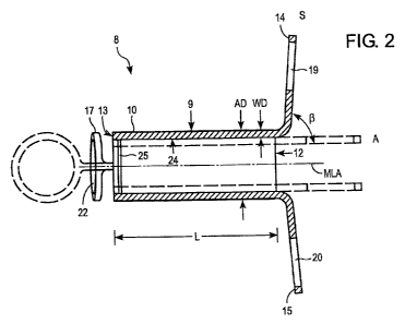
The tracheostoma spacer 8 is shown in more detail in Figures 2 and 3. The
tracheostoma spacer 8 has a tubular support framework 9. The support framework
9
is able to self-expand from an initial state A (shown by broken lines) to a
supporting
state S of increased diameter (shown by solid lines). The length L of the
support
framework can be adjustable. For example, to be able to adjust the length L of
the
CA 02652544 2008-11-17
WO 2007/142812 PCT/US2007/012108
-12-
support framework 9, the support framework can be configured and/or
constructed to
be adjustable. In one embodiment an adjustment means can be provided in the
framework, such as but not limited to a telescoping feature, twisting,
winding, or tilting
of elements in the framework, or a spring force or shape memory behaviour of
the
framework or elements in the framework.
The support framework 9 can be surrounded by a jacket 10 made from a polymer.
The jacket can facilitate the insertion and removal of the tracheostoma spacer
8 and
can avoid injuries to the adjacent tissue 11 (see Fig. 1). The jacket 10 can
also
contain pharmaceutical active substances which have an anti-inflammatory
action
and serve to protect against bacteria.
The support framework 9 can have a circular cross section and can then be cut
particularly easily from a tubular semi-finished product, for example. The
support
framework 9 can be composed of struts (not shown in detail) in the form of
filaments.
The filaments can be made from a shape-memory alloy, in particular from a
nickel-
titanium alloy, also referred to as nitinol, for example.
To keep the tracheostoma 7 as small as possible (see Fig. 1), it is preferable
to have
the support framework 9 with a thin wall thickness. For example, in one
embodiment,
the wall thickness WD of the support framework 9 can be less than one tenth
(1/10)
of the external diameter AD of the support framework 9 in the supporting state
S.
At both ends 12, 13 of the support framework 9, fixing elements 14-17 can be
provided that allow the tracheostoma spacer 8 to be fixed in place in the
trachea 4. In
the supporting state S, the fixing elements 14-17 can be bent at an angle (3
of 80 to
100 , for example, and protrude beyond the outer circumference A of the
support
framework 9. In one embodiment, two fixing elements 14, 15; 16, 17,
respectively,
can be provided at each end 12, 13 and can be arranged lying opposite one
another.
The fixing elements 14, 15 of one end 12 can be offset relative to the fixing
elements
16, 17 of the other end 13 by a right angle a around the central longitudinal
axis MLA
of the support framework 9. To improve the handling of the tracheostoma spacer
8
during its insertion and removal, the fixing elements 14-17 can have circular
apertures 19-22 which make it easier to grip the tracheostoma spacer 8, for
example
CA 02652544 2008-11-17
WO 2007/142812 PCT/US2007/012108
-13-
with a hook-shaped instrument. The fixing elements 14-17 preferably have
atraumatic
edges 23 which are rounded and polished.
Provided on the inside face 24 of the support framework 9, there also can be a
coupling element 25 in the form of a peripheral groove. The coupling element
25
forms an abutment for fixing a valve unit inserted into the support framework
9 or for
fixing a humidifier, or for fixing a tube which has been pushed through and is
also
referred to as a catheter.
A valve unit 26 is shown by way of example in Figures 4 and 5. The valve unit
26 has
a sleeve-shaped middle section 27 which can be adjoined by two beak-shaped
lips
28, 29. Each lip 28, 29 can have a flat portion 30 which is thin and flexible
so that
respiratory air can be inhaled through the valve unit 26 in the direction R
with only
very slight resistance. In the opposite direction, the valve unit 26 is closed
during
exhalation. A further advantage of this valve unit 26 is that tubes and
similar articles
can also be inserted in direction R through the valve unit 26. A coupling
element 32 in
the form of a peripheral spring can be arranged on the outer circumferential
surface
31 of the sleeve-shaped section 27. At its end, the valve unit 26 has a
peripheral
collar 33.
A device 34 for inserting a tracheostoma spacer 8 is shown in Figure 6. This
device
34 is a rigid surgical instrument which can include an internal cutting
instrument 36 in
the form of a trocar 37 and, arranged outside this, a cover sleeve 38. The
trocar 37
can have two very sharp edges 39, 40 with which an opening can be cut in the
trachea. The trocar 37 is arranged on a shaft 41. Behind the trocar 37, there
is a
magazine section 42 of narrower diameter on which a tracheostoma spacer 8 is
placed. This is adjoined by a guide section 43 of greater diameter. The cover
sleeve
38 can be moved by sliding on the guide section 43 of the shaft 41 and can be
pushed over the tracheostoma spacer 8 and can hold the latter in the initial
state
during insertion. At its end, the shaft 41 can have a grip surface 44.
To be able to widen the tracheostoma, a cuff 45 can be arranged on the
periphery of
the cover sleeve 38 and can be filled with a fluid. For this purpose, the cuff
45 has
suitable connector elements 46 for a tube 47.
CA 02652544 2008-11-17
WO 2007/142812 PCT/US2007/012108
-14-
The device 34 for inserting the tracheostoma spacer 8 can make the positioning
of
the tracheostoma spacer 8 much quicker and simpler. The trachea simply can be
punctured to a small diameter in advance. The device 34 is then inserted and
the
correct position in the tracheostoma is verified by bronchoscopy. The cover
sleeve 38
is then drawn back, and the tracheostoma spacer 8 expands, and the fixing
elements
also deploy. Finally, the device 34 simply can be removed again from the
opening.
The tracheostoma spacer 8, according to the invention permits a minimally
invasive
tracheotomy. The radially acting forces during the self-expansion of the
tracheostoma
spacer 8, cause a widening of the tracheostoma 7, so that other auxiliary
devices can
generally be dispensed with. The tracheostoma has a small diameter and heals
within a very short time after removal of the tracheostoma spacer 8.
Figure 7 describes a front view of the tracheostoma spacer 8 after insertion
into a
person. The fixing elements 16, 17 can be seen oriented 180 degrees apart
oriented
side to side. In this figure, the tube guiding elements 48 are depicted as
protrusions
from the inner wall of the tracheostoma spacer, however this is exemplary only
and
the guiding elements can take a variety of forms. The tube guiding elements
can
serve to orient another device, which is to be inserted into the tracheostoma
spacer,
in the proper orientation. Examples of another device to be inserted into the
tracheostoma spacer include but are not limited to a catheter 51, the
tracheotomy
device 34, a tracheostoma spacer removal tool, or an instrument.
Referring to Figure 8, the tracheostoma spacer 8 from Figure 7 is shown in a
cross
section in the person's tissue 11, trachea 4, and tracheal wall 52. A fixing
element 17
on the outside or proximal side are shown as well as the fixing elements 14,
15 on
the inside or distal side, the later oriented 180 degrees apart and 90 degrees
from the
proximal side fixing elements. A tube guiding element 48 is shown as well as a
tube
guiding curve 49, which can serve to guide the device being inserted downward
toward the lung. Also the tube guiding curve 49 can serve to position the
device
being inserted in the desired position, for example away from the posterior or
anterior
tracheal wall to avoid unnecessary or undesired contact with the tracheal wall
52.
CA 02652544 2008-11-17
WO 2007/142812 PCT/US2007/012108
-15-
Although tube guiding curve 49 can function as a safety element, other types
of
safety elements can be provided in accordance with the principles of the
invention.
Referring to Figure 9, an exemplary catheter 51 is described which is intended
to be
inserted into the tracheostoma spacer. Examples of catheters are, but not
limited to:
a ventilation catheter, oxygen therapy cannula, suction catheter, diagnostic
catheter,
a drug delivery catheter, sampling catheter or a fiberoptic catheter. As
described in
Section B-B (Fig. 9B) guiding elements 50 are described which mate with the
tube
guiding elements 48 on the tracheostoma spacer (Figure 7). The guiding
elements
50 are shown in exemplary form only and can comprise a variety of forms and
shapes. A catheter is described in this embodiment as an example, however the
same principles can apply to other devices to be inserted into the
tracheostoma
spacer, such as but not limited to the tracheotomy device 34, a tracheostoma
spacer
removal tool, or an instrument.
List of reference numerals:
1 upper body
2 patient
3 neck
4 trachea
5 oesophagus
6 spinal column
7 tracheostoma
8 tracheostoma spacer
9 support framework
10 jacket
11 tissue
12 end of 9
13 end of 9
14 fixing element
15 fixing element
16 fixing element
17 fixing element
19 aperture
20 aperture
21 aperture
22 aperture
23 edge
24 inside face of 9
25 coupling element
26 valve unit
27 sleeve-shaped section of 26
CA 02652544 2008-11-17
WO 2007/142812 PCT/US2007/012108
-16-
28 lip
29 lip
30 flat section of 28, 29
31 circumferential surface
32 coupling element
33 collar
34 Tracheotomy device
36 cutting instrument
37 trocar
38 cover sleeve
39 edge of 37
40 edge of 37
41 shaft
42 magazine section
43 guide section
44 grip surface
45 cuff
46 connector elements
47 tube
48 Tube Guiding Element
49 Tube Guiding Curve
50 Guiding Element
51 Catheter
52 Tracheal Wall
A outer circumference
AD external diameter
L length
MLA central longitudinal axis
R direction
WD wall thickness
a right angle
R angle
Although the preferred embodiments are directed to tracheostomy, the
principles of
the invention can be applied to other fields, in particular, for example,
other types of
ostomies including colon, or other access devices including vascular.
Moreover, although the foregoing description is directed to the preferred
embodiments of the invention, it is noted that other variations and
modifications will
be apparent to those skilled in the art, and may be made without departing
from the
spirit or scope of the invention. Moreover, features described in connection
with one
embodiment of the invention may be used in conjunction with other embodiments,
even if not explicitly stated above.