Note: Descriptions are shown in the official language in which they were submitted.
CA 02652772 2008-11-18
- 1 -
METHOD AND DEVICE FOR THE REGULATED
FEED OF SUPPLY AIR
FIELD OF THE INVENTION
The present invention relates to a method and device for the regulated feed of
supply air
into a permanently inert space in which a predefined inerting level is set and
needs to be
maintained within a specific control range.
BACKGROUND OF THE INVEITON
Known as a measure to reduce the risk of fire in enclosed spaces such as areas
housing
computer equipment, electrical switchgear and distributor compartments,
enclosed
facilities or storage areas particularly for high-value commodities has been
to render these
spaces permanently inert. The preventative effect resulting from such
permanent inerting
is based on the principle of oxygen displacement. As is generally known,
normal ambient
air consists of approximately 21% oxygen by volume, approximately 78% nitrogen
by
volume and approximately 1% by volume of other gases. To effectively lower the
risk of a
fire breaking out in a protected space, so-called "inert gas technology" is
used to
correspondingly reduce the oxygen concentration in the area at issue by
introducing an
inert gas such as e.g. nitrogen. An extinguishing effect is known to occur in
the case of
most combustible solids when the percentage of oxygen falls below 15% by
volume.
Depending specifically on the combustible materials within the protected
space, it may be
necessary to lower the oxygen content even further, for example to 12% by
volume.
In other words, this means that by subjecting the protected space to permanent
inerting at
a so-called "base inerting level" at which the oxygen content in the air of
the protected
space is reduced for example to below 15% by volume, the risk of a fire
developing in the
protected area can also be effectively reduced.
The term "base inerting level" as used herein is to be generally understood as
a reduced
oxygen content to the air of the protected space in comparison to the oxygen
content of
CA 02652772 2008-11-18
- 2 -
the normal ambient air whereby from a medical standpoint, however, this
reduced oxygen
content does not in principle pose any risk whatsoever to persons or animals
such that
they ¨ perhaps after taking certain precautionary measures depending on the
specific
circumstances ¨ can still enter into the protected space, even if only at
least briefly. As
indicated above, setting a base inerting level having an oxygen content of
e.g. 13-15% by
volume, primarily serves to reduce the risk of a fire from developing in the
protected space.
As distinguished from the base inerting level, the so-called "full inerting
level" corresponds
to the air in the protected space having an oxygen content which has been
reduced to the
point of effective fire extinguishing. The term "full inerting level" thus
refers to an oxygen
content which has been reduced further compared to the oxygen content of the
base inerting
level and at which the inflammability of most material is already lowered to
the point of no
longer being ignitable. Depending on the fire load within the protected space
at issue, the
oxygen concentration at the full inerting level is normally 11% to 12% by
volume. Thus,
permanently rendering the protected space inert at the full inerting level not
only decreases
the risk of a fire developing in the protected space, but also acts to
actually extinguish fire.
SUMMARY OF THE INVENTION
It is desirable on the one hand for permanently inert spaces to be built so as
to be relatively
air-tight, allowing the defined or definable inerting level to be maintained
with the least
amount of inert gas supply possible. On the other hand, however, a certain
minimum
ventilation is generally essential even for permanently inert spaces so as to
permit an
exchange of the air within the atmosphere of the space. In the case of rooms
which people
enter occasionally or which people occupy for extended periods of time, said
minimum air
exchange is needed to allow adequate ventilation of e.g. the exhaled carbon
dioxide or the
moisture given off by these people. It is evident that the minimum air
exchange required for
the space in this example is a function particularly dependent on the number
of people and
the length of time they spend in the room and one which can also vary
considerably,
especially over time.
CA 02652772 2008-11-18
-3 -
Yet a minimum air exchange also needs to be provided even for spaces that
people
essentially never or only very rarely enter, for instance storage or archive
areas or cable
shafts. In this case, minimum ventilation is particularly needed to remove
potentially
harmful components from the spatial atmosphere caused for example by fumes
emanating
from equipment accommodated within the space.
If the respective spatial enclosure is sealed so as to be virtually air-tight,
as is usually the
case especially with permanently inert spaces, uncontrolled air exchange can
no longer take
place. Such enclosed spaces therefore require a technical or mechanical
ventilation system
to provide the required minimum ventilation. The term "technical ventilation"
generally
refers to a ventilation system for drawing off hazardous substances or
biological agents
from an area. In the case of rooms which people occupy, the dimensioning of a
technical
ventilation system; i.e. especially the supply rate, air exchange rate and air
flow velocity,
depends on the time-weighted average concentration of a particular substance
in the
atmosphere of the room at which any acute or chronic damage to a person's
health is not
to be expected. Ventilating the area allows air to be exchanged between the
outside and
the interior atmosphere of the space. In general terms, the required minimum
air exchange
serves to release toxic hazardous substances, gases or particulate matter to
the outside and
take in needed substances, especially oxygen, into areas occupied by people.
Said toxic or
hazardous substances to be removed from the atmosphere of the enclosed space
by the
minimum air exchange will also be simply referred to as "pollutants" in the
following.
Large rooms or areas in which the atmosphere contains a large amount of
hazardous
substances are today typically equipped with a mechanical ventilation system
to ventilate
the room either continuously or at predefined times. The ventilation systems
usually
employed are designed to feed fresh air into the service facilities at issue
and discharge
spent or polluted air. Depending upon application, there are systems for
controlling the
supply air (so-called "air inlet systems"), controlling the exhaust air (so-
called "exhaust
ventilating systems") or combined supply/exhaust air ventilating systems.
CA 02652772 2008-11-18
- 4 -
Yet using such ventilation systems in permanently inert spaces has the
disadvantage that due
to the air exchange effected, inert gas needs to be continuously fed into such
a permanently
inert space at a relatively high rate in order to maintain the set level of
inertization. In order
to maintain a base or full inerting level in a permanently inert space by
mechanically
ventilating the atmosphere, relatively large volumes of inert gas are required
per unit of
time, same being produced on-site for example by the respective inert gas
generators. Such
inert gas generators need to be of correspondingly large dimensions, which in
turn increases
the operating costs for permanent inerting. Moreover, such systems consume a
relatively
large amount of energy in the production of inert gas. Therefore, using inert
gas technology
to render an area permanently inert at a base or full inerting level for the
purpose of
minimizing the risk of fire is economically coupled with relatively high
operating costs when
the permanently inert space requires a minimum exchange of air.
Based on the problem set forth above, one task of the invention is thus to
provide a method
as well as a device designed to supply air to a permanently inert space as
effectively and
economically as possible such that the air exchange rate specified for the
space can be
maintained on the one hand and, on the other, the risk of a fire or explosion
in the space at
issue can be effectively eliminated.
This task is solved by a method of the type indicated at the outset in that
said method com-
prises the following method steps: an inert gas source, particularly an inert
gas generator
and/or inert gas reservoir provides an inert gas, e.g. a nitrogen-enriched air
mixture. The
inert gas provided is then fed into the atmosphere of the permanently inert
space through a
first feed line system at a controlled first volume flow rate, wherein the
first volume flow
rate is adapted so as to maintain the inerting level preset for the spatial
atmosphere of the
permanently inert space and remove pollutants, in particular toxic or other
harmful
substances, biological agents and/or moisture from said atmosphere. The
inventive method
further provides fresh air from a fresh air source, particularly outside air,
wherein the fresh
air provided is then fed into the atmosphere of the permanently inert space
through a
CA 02652772 2008-11-18
- 5 -
second feed line system at a controlled second volume flow rate. In accordance
with the
invention, the value of the second flow rate at which the fresh air is fed
into the atmosphere
of the enclosed space, its mean value over time respectively, is a function of
both the
minimum air exchange rate required for the permanently inert space and the
value of the
first volume flow rate at which the inert gas is fed into the atmosphere of
the space, its
mean value over time respectively.
As used herein, the term "volume flow rate" or "air exchange rate" refers in
each case to
the volume flow or air exchange provided per given unit of time. Similarly,
the term "supply
air rate" refers to the volume of supply air fed into the atmosphere of the
enclosed space
per given unit of time, wherein the term "volume of supply air" refers to the
total amount
of air and gas fed into the atmosphere of the enclosed space. In a permanently
inert space,
e.g. a space being fed on the one hand a specific volume of inert gas per unit
of time in
order to maintain a preset inerting level and, on the other, also being fed a
certain
controlled amount of fresh air per unit of time (in addition to the inert
gas), the supply air
rate is thus the sum of the inert gas rate and the fresh air rate.
The advantages attainable with the inventive solution are obvious: in
particular, the method
is an especially easily-realized yet effective way to economically provide
ample supply air to
a permanently inert space so as to maintain both the specified (minimum) air
exchange rate
for the space as well as maintain the inerting level set for the space,
whereby the risk of a
fire is effectively eliminated within said space.
As used herein, the term "supply air" basically refers to the air/gas
composition fed into the
permanently inert space in order to purge unwanted pollutants, in particular
toxic or
otherwise harmful substances, biological agents and/or moisture (water vapor)
from said
space. Specifically, feeding in supply air serves to discharge to the outside
the toxic
pollutants, gases or particulate matter which are emitted over time within the
spatial
atmosphere, thus in essence "purifying" the air in the space.
CA 02652772 2008-11-18
- 6 -
By setting the value or the mean value over time for the second volume flow
rate at which
fresh air is fed into the atmosphere of the enclosed space as a function of
the minimum air
exchange rate needed to continuously render the space inert and of the value
or the mean
value over time of the first volume flow rate at which the inert gas is fed
into the
atmosphere of the space so as to maintain the predefined inerting level, it is
possible to feed
exactly just that amount of supply air into the atmosphere of the permanently
inert space
per unit of time which is actually necessary to ensure the required minimum
air exchange. In
particular, since the second volume flow rate is advantageously coupled to
temporal
variations in the required minimum air exchange rate and/or the first volume
flow rate, any
time-related fluctuations in the required minimum air exchange which may occur
are also
taken into account. It is hereby conceivable for the value or the mean value
over time of the
second volume flow rate to be correspondingly set as a function of the minimum
air
exchange rate needed at any moment for the permanently inert space and/or as a
function
of the respective value of the first volume flow rate at any given moment.
It is of course also conceivable, as early as the design stage, to
predetermine the required
first and/or second volume flow rate at which the inert gas or the fresh air
is fed into the
atmosphere of the space as a function of the known or any given estimated (or
calculated)
required minimum air exchange rate there might be for the permanently inert
space.
On the other hand, another possible solution would be to predetermine; i.e. in
the design
stage, only the second volume flow rate at which the fresh air is to be fed
into the
atmosphere of the space as a function of the expected value of the first
volume flow rate
and the known or any given estimated (or calculated) required minimum air
exchange rate
there might be for the permanently inert space.
It should be pointed out here that the term "volume flow rate value" as used
in this specifi-
cation refers to the mean value (over time) of the volume flow supplied per
unit of time.
CA 02652772 2008-11-18
- 7 -
The minimum air exchange; i.e. that exchange of air needed to remove toxic or
otherwise
harmful substances, gases and/or particulate matter (hereinafter collectively
referred to
simply as "hazardous substances" or "pollutants") from the spatial atmosphere
at a rate that
reduces the concentration of such hazardous substances in the atmosphere of
the space to a
level which is sufficiently low enough so as to pose no medical danger
whatsoever to living
creatures depends particularly, for example in the case of permanently inert
spaces which
people only enter occasionally, on the number of persons entering and/or the
duration of
time they spend in the room and is in particular not a constant value over
time. In the case
of permanently inert spaces storing goods which release (give off) hazardous
substances
over time, the required minimum air exchange additionally depends on the rate
at which
these hazardous substances are emitted.
On the other hand, in accordance with the inventive solution, the value or the
time-based
mean value of the first volume flow rate at which the inert gas supplied by
the inert gas
source is fed into the atmosphere of the permanently inert space via the first
feed line
system can be set or regulated such that the oxygen concentration in the
permanently inert
space will not exceed a predefinable level. Said predcfinable level can for
example
correspond to the pre-set inerting level to be maintained (within a certain
control range) in
the permanently inert space.
What is hereby essential, however, is that the method according to the
invention ensures, by
regulating the feed of inert gas at the first volume flow rate and regulating
the feed of fresh
air at the second volume flow rate, that the total amount of air supplied per
unit of time will
be dimensioned so as to maintain the inerting level preset for the permanently
inert space
on the one hand and, on the other, ensure the necessary minimum air exchange
rate. Since
the supply air fed into the spatial atmosphere consists of a specific amount
of fresh air and
a specific amount of inert gas, the required air exchange can be ensured in a
particularly
cost-effective manner, even for permanently inert spaces.
CA 02652772 2008-11-18
- 8 -
I t should be noted in conjunction hereto that the term "inert gas" as used
herein refers in
particular to oxygen-depleted air. Such oxygen-depleted air can for example be
nitrogen-
enriched air.
Given permanently inert spaces which people only enter occasionally, for
example, and
which ideally contain no toxic hazardous substances, particularly from the
vaporizing or
dissipating of highly-volatile substances ¨ with the exception of the carbon
dioxide exhaled
by these persons or the moisture generated by their presence in the room ¨ the
supply air
needed to be fed into said space per unit of time; i.e., the supply air rate
which is regulated
according to the inventive method by way of the value or time-based mean value
of the
second volume flow rate and the value or time-based mean value of the first
volume flow
rate, depends on the carbon dioxide or moisture content on the one hand and,
on the other,
on the reduced oxygen concentration within the spatial atmosphere.
Thus, in this (idealized) example, the minimum air exchange rate needed for
the permanent-
ly inert space would be at a value of "zero" when there are no people in the
permanently
inert space and consequently no substances (carbon dioxide, moisture) being
generated in
the atmosphere of said permanently inert space which would need to be removed.
The proposed solution would thus set the value of the second volume flow rate
at which
fresh air is supplied to the spatial atmosphere at zero while the value for
the first volume
flow rate at which inert gas is fed into the spatial atmosphere would be set
to a level which
would be sufficient to maintain the specified inerting level within the
spatial atmosphere.
When, however, one or more persons enter the space, resulting in the carbon
dioxide and/or
moisture concentration in the spatial atmosphere exceeding a predefinable
critical value (after
a certain amount of time), a minimum exchange of air becomes necessary to keep
the carbon
dioxide and humidity ratios within the spatial atmosphere at a non-toxic or
safe level, respec-
tively reduce said ratios to a non-toxic or safe level. At the same time, the
first volume flow
CA 02652772 2008-11-18
- 9 -
rate at which inert gas is fed into the spatial atmosphere of the space must
essentially assume
a value which will suffice to maintain the specific inerting level within said
atmosphere.
Since in terms of the inert gas feed specifically contributing to the required
minimum air
exchange, it is not only the percentage of harmful substances or pollutants
needing to be
discharged from the spatial atmosphere of the permanently inert space which
has to be
taken into account when establishing the value of the second volume flow rate,
but also the
value of the first volume flow rate at which the inert gas itself is supplied
into said spatial
atmosphere, the solution according to the invention essentially provides for
just enough
fresh air to be supplied into the atmosphere of the permanently inert space as
is absolutely
necessary to dissipate the volume of pollutants from the spatial atmosphere
which was not
already dissipated by the inert gas feed, e.g. by means of a corresponding
exhaust air
discharge system.
It is thus conceivable that when the minimum air exchange requirement is low
enough, the
amount of inert gas supplied to the spatial atmosphere per unit of time may
already suffice
for the necessary exchange of air such that there is no need to supply any
further fresh air.
In other words, in this particular case, the inert gas introduced at the first
volume flow rate
already suffices to ensure the required minimum air exchange.
In terms of the device, the task on which the invention is based is solved by
the device
comprising the following: an inert gas source, in particular an inert gas
generator and/or an
inert gas reservoir for supplying an inert gas; a fresh air source for
supplying fresh air, in
particular outside air; a first feed line system connectable to the inert gas
source for the
regulated feeding of the available inert gas into the spatial atmosphere of
the permanently
inert space at a first volume flow rate which is set so as to maintain the
predefined inerting
level and to adequately discharge pollutants, in particular toxic or otherwise
hazardous
substances, biological agents and/or moisture from the spatial atmosphere; and
a second
feed line system connectable to the fresh air source for the regulated supply
of available
fresh air into the spatial atmosphere of the permanently inert space at a
second volume flow
CA 02652772 2008-11-18
- 10 -
rate. The invention accordingly provides for the value of the second volume
flow rate at
which the fresh air is supplied to be a function of both the minimum air
exchange rate
required for the permanently inert space and the value of the first volume
flow rate at which
the inert gas is supplied.
The device as specified constitutes a design-based implementation for
realizing the above-
described method of regulating the feed of supply air into a permanently inert
space. It is
obvious that the advantages and features described above in conjunction with
the inventive
method are analogously attainable with the inventive device.
Advantageous further embodiments respective the method are set forth in claims
2 to 12
and respective the device in claims 13 to 25.
One particularly preferred embodiment of the method according to the invention
provides
for the pollutant concentration within the spatial atmosphere to be measured
at one or a
plurality of locations within the permanently inert space, preferably
continuously or at
predefined times or upon predefined event, by means of one or a plurality of
sensors.
One particularly advantageous realization preferably makes use of an
aspirative pollutant
measuring device having at least one and preferably a plurality of pollutant
sensors
operating in parallel, wherein the pollutant concentration measured
continuously or at
predefined times or upon predefined events is transmitted as a measurement
reading to at
least one control unit.
The at least one control unit can be designed so as to regulate the value of
the first volume
flow rate at which the inert gas is fed into the spatial atmosphere of the
permanently inert
space as a function of the inerting level to be maintained in said permanently
inert space.
Alternatively or additionally thereto, however, it is also conceivable for the
control unit to
be designed such that it regulates the value of the first volume flow rate at
which the inert
gas is fed as a function of the minimum air exchange required within the
permanently inert
REPLACEMENT SHEET
CA 02652772 2008-11-18
- H -
space and/or as a function of the value of the first volume flow rate at which
the inert gas
is supplied.
It is hereby conceivable for the control unit to regulate the value of the
second volume flow
rate as a function of the minimum air exchange rate required within the
permanently inert
space at any given moment and/or as a function of the respective momentary
value of the
first volume flow rate.
It is of course also conceivable to predetermine, as early as the design
stage, especially the
specific second volume flow rate at which the fresh air is to be supplied to
the spatial
atmosphere as a function of the known or any estimated required minimum air
exchange
rate there might be for the permanently inert space and/or the air-tightness
to the spatial
enclosure, the associated ns, value of the space respectively.
The advantage of employing a plurality of pollutant sensors working in
parallel to detect the
pollutant concentration within the spatial atmosphere relates particularly to
the pollutant
measuring device affording fail-safe detection. Since the control unit is fed
the pollutant
concentration preferably on a continuous basis or at predefined times or upon
predefined
events, it is advantageously possible for the control unit to establish or
restore the minimum
air exchange needed for the permanently inert space concurrently to measuring
the pollutant
concentration.
Since the system according to the invention is thus cognizant of the minimum
air exchange
rate needed to be maintained in the space, it is possible for the value of the
second volume
flow rate at which fresh air is fed into the spatial atmosphere to be
preferably continuously
adapted to said minimum air exchange rate required for the permanently inert
space. As
stated above, the value of the supply air rate (i.e. the amount of supply air
fed into the
permanently inert space per unit of time) is composed of the value of the
first volume flow
rate plus the value of the second volume flow rate (i.e. of the amount of
inert gas supplied
to the spatial atmosphere per unit of time and the amount of fresh air
supplied to the spatial
CA 02652772 2008-11-18
-12-
atmosphere per unit of time). The required minimum air supply rate is just
that amount of
supply air which needs to be supplied to the atmosphere of the permanently
inert space per
unit of time so as to remove pollutants, etc. from the spatial atmosphere to
the point where
the concentration of said pollutants is just low enough to be safe for persons
or for good
stored in the permanently inert space.
One particularly preferred realization of the inventive solution further
provides for
measuring the oxygen concentration in the permanently inert space at one or a
plurality of
locations within said spatial atmosphere, preferably continuously or at
predefined times or
upon predefined events. It would hereby be conceivable to provide a preferably
aspirative-
type oxygen measuring device having at least one and preferably a plurality of
oxygen
sensors working in parallel to measure the oxygen concentration in the
atmosphere of the
permanently inert space either continuously or at predefined times or upon
predefined
events and forward the measurement readings to the control unit.
The use of a plurality of oxygen sensors working in parallel is preferred in
terms of the fail-
safe operation of the oxygen measuring device. Since the control unit
registers the pre-
vailing oxygen concentration in the spatial atmosphere of the permanently
inert space at any
given time, it can regulate the value of the first volume flow rate at which
the inert gas is
fed into the spatial atmosphere to a point suited to maintaining the inerting
level specified
for said permanently inert space (within a certain control range as needed).
The system
according to the invention thus thereby ensures sufficient protection against
fire and ¨
when the oxygen concentration in the spatial atmosphere respective the preset
inerting level
is sufficiently low enough ¨ also against explosions, even while a regulated
exchange of air
in the atmosphere of the permanently inert space occurs.
Since according to the invention, the supply air rate needed to be supplied
the space to
ensure the required minimum air exchange not only takes into account the value
of the
second volume flow rate at which fresh air is fed into the spatial atmosphere
but also the
value of the first volume flow rate at which inert gas is fed into the spatial
atmosphere, only
CA 02652772 2008-11-18
- 13 -
that much supply air is in principle fed into the spatial atmosphere per unit
of time as is
actually needed to ensure said minimum air exchange. To this end, the value of
the second
volume flow rate is ideally set at a value corresponding to the difference
between a
minimum supply air value flow rate, or supply air rate, needed to maintain the
minimum air
exchange required for the permanently inert space and/or the value of the
first volume flow
rate for maintaining the specified inerting level. Of course, it is also
conceivable to
intentionally select a somewhat higher value for the second volume flow rate
so as to
guarantee an extra margin of safety with regard to the minimum air exchange
required.
With the solution according to the invention, the above-cited minimum supply
air volume
flow rate or supply air rate at least needed to maintain the required minimum
air exchange
rate in the permanently inert space can be determined by means of the at least
one control
unit as function of the measured concentration of pollutants within the
spatial atmosphere
of the permanently inert space. It would hereto be conceivable to provide the
corresponding look-up table in said control unit which defines a relationship
between the
measured pollutant concentration and the required minimum supply air volume
flow rate.
To have the system be as flexible as possible in terms of adapting to
potentially changing
concentrations of pollutants within the atmosphere of the permanently inert
space, it is
hereby preferably provided for the control unit to determine the necessary
minimum supply
air volume flow rate continuously or at predefined times or upon predefined
events.
On the other hand, however, it is also conceivable to predetermine,
particularly in the
design stage of the device, the setting of the second volume flow rate at
which fresh air
will be fed into the spatial atmosphere as a function of the known or any
estimated required
minimum air exchange rate there might be, wherein this determination
preferably also takes
into account the air-tightness to the spatial enclosure of the permanently
inert space; i.e.
the n5õ value for the space.
CA 02652772 2008-11-18
-14-
All in all, the control unit is preferably designed so as to increase the
minimum air exchange
rate required for the permanently inert space as the concentration of
pollutants rises within
said space, and to correspondingly lower it as the pollutant concentration
decreases.
On the other hand, the control unit also needs to be designed to set the value
of the second
volume flow rate as a function of the minimum air exchange rate and as a
function of the
value of the first volume flow rate, preferably by controlling a valve
provided in the second
feed line system, such that the value of the second volume flow rate is
greater than or equal
to the difference between the minimum supply air volume flow rate needed to
maintain the
minimum air exchange required for the permanently inert space and the value of
the first
volume flow rate needed to maintain the specified inerting level in the
atmosphere of the
permanently inert space.
It would of course also be conceivable to design the control unit so as to set
the value for
the first volume flow rate as a function of the minimum air exchange rate and
as a function
of the value conceivably already set for the second volume flow rate during
the device
design stage, preferably by controlling a valve provided in the first feed
line system such
that said value of the first volume flow rate is greater than or equal to the
difference
between the minimum supply air volume flow rate needed to maintain the
required
minimum air exchange in the permanently inert space and the predetermined
second volume
flow rate, wherein of course to be kept in mind hereby is that the first
volume flow rate
should in principle assume a value as required for maintaining the specified
inerting level in
the atmosphere of the permanently inert space.
In order to detect the values of the first and second volume flow rates
serving to maintain
the set inerting level in the permanently inert space or maintain the required
minimum air
exchange rate as respectively established by the control unit, one preferred
realization of the
inventive system provides for at least one sensor each at one or a plurality
of locations
within the first and second feed line systems for the purpose of measuring the
first,
CA 02652772 2008-11-18
- 15 -
respectively second volume flow rate, preferably continuously or at predefined
times or
upon predefined events, and routing the measurement readings to the control
unit.
The fresh air source may for instance be in the form of a system that draws in
"normal"
outside air, in which case the fresh air supplied by the fresh air source is
ambient outside air.
A particularly preferred embodiment of the device according to the invention
additionally
provides for an exhaust discharge mechanism designed to extract exhaust air
from the
atmosphere of the permanently inert space in regulated fashion. This exhaust
discharge
mechanism may be a ventilation system based on the principle of positive
pressure
ventilation for example, wherein the feed of supply air creates a certain
excess pressure in
the permanently inert space such that the pressure differential causes a
portion of the spatial
air to be discharged from the permanently inert space through a corresponding
exhaust pipe
system. Of course, an exhaust discharge mechanism using e.g. fans to actively
draw out air
from the space would also be conceivable.
In the latter embodiment in which the device for the regulated feed of supply
air into the
permanently inert space is further provided with an exhaust discharge
mechanism, it is
particularly preferred for same to additionally comprise an air treatment unit
to process
and/or filter the exhaust air removed from the space by the exhaust discharge
mechanism
and to subsequently re-feed at least a portion of the processed or filtered
exhaust air back to
the inert gas source as available inert gas. The air treatment unit should
thereby be designed
so as to filter out any toxic or otherwise harmful hazardous substances, gases
or particulate
matter there might be from the extracted exhaust air such that the filtered
exhaust air is
directly reusable as inert gas.
It would however also be conceivable in the latter embodiment for the air
treatment unit to
comprise a molecular separation system, in particular a hollow fiber membrane
system, a
molecular sieve system and/or an activated charcoal adsorption system so as to
provide
molecular filtering of the exhaust air extracted from the space.
CA 02652772 2008-11-18
-16-
In a case in which an inert gas generator comprising a membrane system and/or
an
activated charcoal adsorption system is used as the inert gas source and a
compressed air
mixture is supplied to the inert gas generator, wherein the inert gas
generator then dispenses
a nitrogen-enriched air mixture, it would be further conceivable for the air
mixture fed to
the inert gas generator to contain at least a portion of the filtered exhaust
air.
In a particularly preferred realization of the exhaust discharge mechanism,
same comprises
at least one controllable exhaust flap, in particular a mechanically,
hydraulically or
pneumatically actuatable exhaust flap which can be controlled so as to
discharge the exhaust
air from the permanently inert space in regulated fashion. It would be
conceivable to have
the exhaust flap be designed as a fire damper.
Specifically, in the above-preferred embodiment of the inventive device
comprising the
exhaust discharge mechanism and the air treatment unit, it is preferable for
the oxygen
content in the volume of filtered exhaust air fed to the inert gas source as
an inert gas to be
at most 5% by volume, making this a very economical system to operate.
With regard to the predefinable level that can be set for the permanently
inert space, it is
specifically provided for same to be lower than the oxygen content of the
outside air and
higher than the specified inerting level to be maintained in the permanently
inert space.
Lastly, from an economic standpoint, it is particularly preferred in the above-
described
embodiments of the inventive device provided with an inert gas source as well
as a fresh
air source for the percentage of oxygen in the inert gas supplied by the inert
gas source
to be 2% to 5% by volume, and the percentage of oxygen in the fresh air
supplied by the
fresh air source to be approximately 21% by volume. Of course, other
percentages are
also conceivable.
CA 02652772 2008-11-18
- 17 -
With regard to the method according to the invention, one preferred embodiment
additionally provides for the method step of producing the inert gas. It is
thus possible,
given the applicable mechanism, for on-site production of the inert gas which
might be
mixed into the supply air fed into the permanently inert space as needed.
It is moreover preferred for the method to comprise the method step of
regulated
extraction of the exhaust air from the permanently inert space by means of a
corresponding
exhaust discharge mechanism as well as the further method step of filtering
the exhaust air
extracted from the space by said exhaust discharge mechanism, wherein at least
a portion of
the filtered exhaust air is made available as inert gas.
Finally, it would also be conceivable to measure the oxygen content in the
spatial
atmosphere of the permanently inert space, preferably continuously or at
predefined times
or upon predefined events, wherein the method step of regulating the volume
flow rate of
the inert gas supplied by the inert gas source, the method step of regulating
the volume flow
rate of the fresh air supplied by the fresh air source respectively, ensues as
a function of the
measured oxygen content.
BRIEF DESCRIPTION OF THE DRAWINGS
The following will reference the included drawings in describing preferred
embodiments
of the inventive device.
Shown are:
Fig. 1 a first preferred embodiment of the device according to the
invention for the
regulated feed of supply air into a permanently inert space;
Fig. 2 a second preferred embodiment of the device according to the
invention for the
regulated feed of supply air;
Fig. 3 a third preferred embodiment of the device according to the
invention for the
regulated feed of supply air;
CA 02652772 2008-11-18
-18-
Fig. 4a, b a temporal plotting of the valve control for the regulated feed of
inert gas and
supply air in one realization of the invention's preferred embodiments.
DETAILED DESCRIPTION OF THE INVENTION
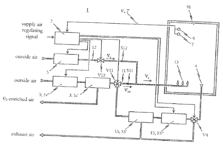
Fig. 1 shows a schematic view of a first preferred embodiment of the device 1
according to
the invention for the regulated feed of supply air into a permanently inert
space 10. As
depicted, device 1 for the regulated feed of supply air into a permanently
inert space 10
functions as a supply air regulating mechanism essentially comprising a
control unit 2, a
fresh air source 5 to supply fresh air (in this case outside air) and an inert
gas source 3 to
supply an inert gas such as e.g. nitrogen-enriched air.
The device 1 according to the invention as shown in Fig. 1 additionally
comprises a first feed
line system 11 and a second feed line system 12 for the regulated feeding of
available inert
gas, available fresh air respectively, into the spatial atmosphere of
permanently inert space 10.
Both feed line systems 11, 12 respectively connect the inert gas source 3 and
the fresh air
source 5 to a discharge nozzle system 13 provided in the permanently inert
space 10.
In all of the embodiments described herein, the discharge nozzle system 13 is
designed as
a nozzle system shared jointly for the feed of both inert gas and fresh air;
of course, it
would also be conceivable to provide separate nozzle systems.
A valve V11, V12 actuatable by the control unit 2 is provided in both the
first and second
feed line systems 11 and 12. Specifically, the valve V11 provided in the first
feed line
system 11 is designed so as to be correspondingly actuatable by the control
unit 2 such
that the inert gas supplied by the inert gas source 3 is fed into the
atmosphere of the
permanently inert space 10 at a regulated first volume flow rate VN7. In turn,
the valve V12
provided in the second feed line system 12 is designed so as to be
correspondingly
actuatable by the control unit 2 such that the fresh air supplied by the fresh
air source 3
(in this case outside air) is fed into the atmosphere of the permanently inert
space 10 at a
regulated second volume flow rate VE.
CA 02652772 2008-11-18
- 19 -
In one preferred realization of the device according to the invention, the
valves V11 and
VI2 are designed as stop valves which can be switched between an open and a
closed state.
Figs. 4a and 4b show the respective temporal plotting of the control unit 2
opening and
closing valves V11 and V12 in this realization. It can be seen here that the
fresh air and the
inert gas are pulse-dispensed by the inert gas source 3, the fresh air source
5 respectively. It
is in particular noted that the value of the first volume flow rate VN, at
which the inert gas is
fed into the atmosphere of the permanently inert space 10 and the value of the
second
volume flow rate V1, at which the fresh air is fed into the atmosphere of the
permanently
inert space 10 are in each case mean values over time.
Valve V11 provided in the first feed line system 11 is actuated particularly
for regulating the
oxygen concentration (or inert gas concentration) in the atmosphere of the
permanently
inert space 10. To that end, valve V11 is set such that the first volume flow
rate V\-, fed into
space 10 is preferably at a value which is preferably just enough to maintain
the predefined
inerting level set for the atmosphere of permanently inert space 10 (given a
certain control
range as needed).
In order to be able to set the first volume flow rate VN, such that the
inerting level in the
permanently inert space 10 can be maintained in space 10 as precisely as
possible or a
predefined inerting level can be set in said space 10 as precisely as possible
with the device
1 according to the invention, the preferred embodiment of the inventive device
shown in
Fig. 1 additionally comprises an oxygen measuring device 7' having at least
one and prefer-
ably a plurality of oxygen sensors 7 working in parallel to measure the oxygen
concentration
in the atmosphere of permanently inert space 10 continuously or at predefined
times or
upon predefined events and transmit the measurement readings to the control
unit 2.
Although not explicitly shown in Fig. 1, it is particularly preferred for the
oxygen measuring
device 7' to be an aspirative-based system.
Valve V12 provided in the second feed line system 12 is in turn controlled as
a function of
the minimum supply air rate required for the permanently inert space 10; i.e.
precisely that
REPLACEMENT SHEET
CA 02652772 2008-11-18
- 20 -
air supply rate which is just enough to ensure the minimum air exchange
required in space
10. As explained above, the minimum supply air rate; i.e. the amount of supply
air to be fed
into the permanently inert space 10 per unit of time, is composed of the first
volume flow
rate VN, and the second volume flow rate V1, (i.e. the amounts of inert gas
and fresh air fed
into the spatial atmosphere per unit of time). Specifically, the minimum
supply air rate is
that supply rate which is just enough to remove pollutants and the like from
the spatial
atmosphere to the extent that the concentration of said pollutants in the
spatial atmosphere
is safe for people or for goods stored within the permanently inert space 10.
Since according to the invention, the determination of the value for the air
supply rate into
space 10 for ensuring the required minimum exchange of air takes both the
second volume
flow rate VI, at which fresh or outside air is fed into the spatial atmosphere
as well as the
first volume flow rate VN, at which inert gas is fed into the spatial
atmosphere into account,
the preferred embodiments of the invention provide for the valve V12 provided
in the
second feed line system 12 to be regulated by the control unit 2 such that the
second
volume flow rate V1 will be at a value or a time-based mean value which allows
only that
much supply air to be fed into space 10 as is actually necessary to ensure the
minimum
exchange of air. To this end, the second volume flow rate VI, assumes a value,
ideally by the
appropriate activation of valve V12, which corresponds to the difference
between the
minimum supply air volume flow rate or supply air rate needed to maintain thc
required
minimum air exchange in the permanently inert space 10 and the first volume
flow rate VN,
set to maintain the predefined inerting level. In order to ensure an added
margin of safety
with regard to the required minimum air exchange, however, it is also
conceivable to
intentionally select a somewhat higher second volume flow rate V1,.
Valves V11 and V12 are thus actuated with respect to the minimum supply air
volume flow
rate or supply air rate Vu so as to yield the following relationship between
the first volume
flow rate VN, and the second volume flow rate V1,:
VN, ?_
CA 02652772 2008-11-18
-21 -
The necessary minimum supply air volume flow rate Vi; can be determined e.g.
by means of
a pollutant measuring device 6' comprising at least one and preferably a
plurality of pollutant
sensors 6 working in parallel which measure the concentration of pollutants in
the
atmosphere of the permanently inert space 10 continuously or at predefined
times or upon
predefined events and transmit the measurement readings to the control unit 2.
As in the
case with the oxygen measuring device 7', the pollutant measuring device 6' is
preferably of
aspirative design.
It would hereby be conceivable for the control unit 2, on the basis of the
measured pollu-
tant concentration, to subsequently determine the required minimum supply air
volume flow
rate VI, either continuously or at predefined times or upon predefined events
using a table
stored in said control unit 2. This table should specify a correlation between
the measured
pollutant concentration and the required minimum supply air volume flow rate
VI,. While it
is not imperative to do so, this relationship can also be adapted to the
physical properties of
the relevant space 10 such that e.g. the spatial volume, the actual use of the
room and other
parameters can be taken into account.
It would, however, of course also be conceivable to preset a minimum air
exchange rate to
be maintained by means of a supply air regulating signal input into control
unit 2, wherein
said preset value is then used in calculating the second volume flow rate.
Lastly, it is further conceivable to design the control unit 2 such that,
depending upon the
minimum air exchange rate or minimum required supply air volume flow rate V,.
and the
value of the second volume flow rate Võ, potentially set during the device
design stage,
preferably by regulating the valve V11 provided in the first feed line system
11, the value or
time-based mean value of the first volume flow rate VN, can be set such that
the value or
time-based mean value of said first volume flow rate VN, is greater than or
equal to the
difference between the minimum supply air volume flow rate V17 required to
maintain the
minimum air exchange in the permanently inert space and the preset second
volume flow
rate VL, whereby of course keeping in mind that the first volume flow rate VN,
should
CA 02652772 2008-11-18
-22 -
essentially be at a value or time-based mean value as is required for
maintaining the
specified inerting level for the atmosphere of the permanently inert space.
Generally speaking, however, the value of the second volume flow rate V1,
depends on the
value of the first volume flow rate \TN,. It is therefore preferable to
measure the first
volume flow rate VN, at one or a plurality of locations within the first feed
line system 11,
particularly continuously or at predefined times or upon predefined events, by
means of a
suitable volume flow sensor S11 and to transmit the readings to the control
unit 2. It would,
however, of course also be conceivable to determine the first volume flow rate
V\-, as a
function of the control signal which the control unit 2 sets for the volume
flow regulator
V11 provided in the first feed line system 11.
It is in turn also preferable for at least one sensor S12 to be additionally
provided at one or
a plurality of locations within the second feed line system 12 so as to
measure the value of
the second volume flow rate V1,, preferably continuously or at predefined
times or upon
predefined events, and transmit the readings to the control unit 2.
As indicated above, it is in principle conceivable to input a corresponding
supply air
regulating signal into control unit 2 instead of the measured values provided
by the
pollutant measuring device 6', wherein said supply air regulating signal
establishes the
minimum air exchange rate required for the permanently inert space 10.
Alternatively or
additionally hereto, it is further conceivable for the supply air regulating
signal to contain
information on the value needed for the first volume flow rate VN, in order to
maintain the
inerting level set for the permanently inert space 10 (given a certain control
range as
needed) by the continuous feeding in of inert gas. In the case, there would
then be no need
for oxygen measuring device 7'.
The fresh air source 5 in the embodiment depicted in Fig. 1 is a compressor
that is or can
be activated by the control unit 2 which is designed to draw in "normal"
outside air and
CA 02652772 2008-11-18
- 23 -
which provides the second feed line system 12 with the respective fresh air
volume flow
rate V1, when activated by control unit 2.
The inert gas source 3 depicted in Fig. 1 is an inert gas generating system
comprised of a
compressor 3a" which is or can be activated by the control unit 2 and a
molecular
separation system 3a', in particular a membrane or activated charcoal
adsorption system. In
the first preferred embodiment, the compressor 3a" compresses "normal" outside
air and
then feeds it to the molecular separation system 3a'. Since the control unit 2
regulates the
volume flow rate of the compressed air delivered by the compressor 3a" to the
molecular
separation system 3a', it is possible to appropriately set the volume flow
rate VN, ultimately
supplied by the inert gas source 3 to the first feed line system 11. Of
course, this process
can also ensue by the suitable control of the volume flow regulator V11
provided in the first
feed line system 11.
Alternatively or additionally to the inert gas generating system 3a', 3a", it
would also be
conceivable for the inert gas source 3 to comprise an inert gas reservoir 3b,
as indicated in
Fig. 1 by the dashed lines. This inert gas reservoir 3b can take the form of a
battery of gas
cylinders, for example. The inert gas volume flow rate Vx, provided by the
inert gas reser-
voir 3b of the first feed line system 11 should be adjustable by the
regulating valve V11
correspondingly controlled by the control unit 2.
According to the invention, the value or time-based mean value of the amount
of supply air
fed to the permanently inert space 10 per unit of time is set so as to, on the
one hand, suffi-
ciently expel the pollutants present in the atmosphere of the permanently
inert space 10 and,
on the other, maintain the inerting level set for said permanently inert space
10. In particular,
however, the determination of the value or time-based mean value of the second
volume flow
rate V1, according to the inventive solution not only takes into account the
proportional
concentration of pollutants to be removed from the atmosphere of permanently
inert space
but also the value or time-based mean value for the first volume flow rate VN2
at which
inert gas is fed into the spatial atmosphere so that the first volume flow
rate VN, will con-
REPLACEMENT SHEET
CA 02652772 2008-11-18
- 24 -
tribute to some degree to the required minimum air exchange such that only
that much fresh
air will be supplied to the atmosphere of permanently inert space 10 as is
absolutely necessary
to expel the pollutant concentration from said spatial atmosphere which has
not already been
expelled by the supply of inert gas with the respective exhaust discharge
system 4.
In conjunction hereto, an exhaust discharge mechanism 4 in the form of an
exhaust flap is
additionally provided in permanently inert space 10 in the Fig. 1 embodiment,
through
which exhaust air is extracted from permanently inert space 10. In the
preferred embodi-
ment as depicted, the exhaust discharge mechanism 4 is a passive system
operating on the
principle of positive pressure. The exhaust flap of said exhaust discharge
mechanism 4 is
configured as a non-return flap valve.
To summarize, it can be established that the solution according to the
invention makes it
possible to always feed just enough fresh/outside air into the atmosphere of
the permanent-
ly inert space 10 as is needed to ensure the required minimum air exchange.
If, for example,
the required minimum air exchange for the permanently inert space 10 requires
an input of
fresh air at 1000 m3/day, the invention would then conceivably allow e.g. 700
m3 of outside
air and 300 m3 of nitrogen-enriched air or oxygen-depleted air to be
introduced on a daily
basis into space 10. An example of oxygen-depleted air which could be used
would be air
having a nitrogen content of 90-95% by volume. The percentage of oxygen-
depleted air is
calculated on the basis of the residual oxygen concentration in the oxygen-
depleted air, the
base inerting level to be set for the space, the dimensional volume of the
space and its air-
tightness.
Fig. 2 shows a preferred further development of the first embodiment of the
inventive device 1 as
depicted in Fig. 1. The second embodiment shown in Fig. 2 differs from the
first embodiment
according to Fig. 1 in that not all of the exhaust air drawn out of
permanently inert space 10 by means
of the exhaust discharge mechanism 4 is discharged to the outside atmosphere
but rather at least a
portion of it is routed through a filter system 15 and then
REPLACEMENT SHEET
CA 02652772 2008-11-18
- 25 -
recirculated back into the first feed line system 11 by way of the
controllable valve V11
provided in said first feed line system 11.
What this "inert gas feedback" thus correspondingly effects is the filter
system 15 purifying
a portion of the exhaust air extracted from the permanently inert space 10 by
the exhaust
discharge system 4 during the regulated air exchange and then it being
resupplied to the
permanently inert space 10 as inert gas.
The exhaust air purification effected by the filter system 15 needs to
separate the toxic or
harmful hazardous substances from the exhaust air extracted from permanently
inert space
10, thus permitting the ultimately-purified exhaust air to be ideally directly
re-fed into space
10. Since the purified exhaust air contains a percentage of oxygen which is
identical to the
oxygen content in the spatial atmosphere of permanently inert space 10, there
would be no
need in the case of loss-less feedback, thus constituting a fully-closed
feedback loop, and of
a hermetically-sealed spatial enclosure to permanently inert space 10, for any
additional inert
gas to be added from the inert gas source 3 or any additional fresh air to be
added from the
fresh air source 5 to the purified exhaust air in order to ensure the minimum
air exchange
required on the one hand and, on the other, maintain the specified inerting
level with the
permanently inert space 10.
In practice, however, such a loss-less inert gas feedback loop or hermetically-
sealed spatial
enclosure is often not the case such that the second preferred embodiment of
the invention,
as illustrated in Fig. 2, also provides for a fresh air source 5 as well as an
inert gas source 3,
each actuatable by the control unit 2, with their associated gas volume flow
rates VNõ
regulated either by direct activation by control unit 2 or by said control
unit 2 effecting
activation of the corresponding valves V11, V12.
As shown in Fig. 2, the inert gas feedback loop is provided with a three-way
valve V4
actuatable by the control unit 2 for setting the percentage of exhaust air
removed from the
CA 02652772 2008-11-18
- 26 -
permanently inert space 10 which is then fed to the filter system 15 of the
inert gas
feedback loop and ultimately re-introduced into space 10 as purified supply
air.
As indicated above, the filter system 15 provided in the inert gas feedback
loop must be
designed so as to separate toxic or harmful pollutants contained in the
portion of the
exhaust air fed to the inert gas feedback loop. Particularly well-suited to
this task is an air
treatment unit 15 comprising a molecular separation system 15', in particular
a hollow fiber
membrane system and/or an activated charcoal adsorption system. In the present
case, the
air treatment unit 15 is additionally equipped with a compressor 15" which
compresses the
portion of the exhaust air fed to the inert gas feedback loop and then routes
it to the
molecular separation system 15'.
The molecular separation system 15' molecularly splits the compressed exhaust
air such that
the toxic or harmful components (pollutants) are separated from the exhaust
air extracted
from the permanently inert space 10, discharging them to the outside through a
first outlet.
As Fig. 2 shows, a second outlet of the molecular separation system 15' can in
turn be
connected to the first feed line system 11 by way of valve V11 so that at
least a portion of
the purified exhaust air can be fed to the first feed line system 11 as inert
gas.
In other words, this means that the Fig. 2 embodiment comprising the inert gas
feedback
loop and the air treatment unit 15 constitutes an inert gas exchanger. In
order to regulate
the inert gas feedback rate, it is preferably provided for the control unit 2
to actuate the
control valve V4 at the inlet of the generator 15" and/or the generator 15"
itself.
Fig. 3 shows a preferred further development of the second embodiment. Hereby
provided
as the inert gas source ¨ as is also the case with the first and second
embodiments pursuant
Figs. 1 and 2 ¨ is an inert gas generator 3a comprising a molecular separation
system 3a',
particularly a hollow fiber membrane system or an activated charcoal
adsorption system,
wherein the inert gas generator 3a is fed a compressed air mixture and
dispenses a nitrogen-
enriched air mixture, and wherein the nitrogen-enriched air mixture dispensed
by the inert
CA 02652772 2008-11-18
- 27 -
gas generator 3a is control-fed as an inert gas to the first feed line system
11, the
permanently inert space 10 respectively.
The embodiment illustrated in Fig. 3 additionally comprises an exhaust
discharge mechanism
4 designed to extract exhaust air from the permanently inert space 10 in
regulated fashion,
preferably based on the positive pressure principle, and to allow at least a
portion of the ex-
tracted exhaust air to pass through an air treatment unit 15 in order to
filter this portion of
the exhaust air extracted from space 10 by the exhaust discharge mechanism 4.
At least a
portion of the filtered exhaust air is then fed to the compressor 3a" of inert
gas source 3.
In contrast to the second embodiment shown in Fig. 2, the third embodiment
according to
Fig. 3 does not require the air treatment unit 15 provided in the inert gas or
exhaust air
feedback loop to be equipped with a compressor, as identified in Fig. 2 by the
reference
numeral 15", or a molecular separation system, identified in Fig. 2 by the
reference numeral
15', in order to separate the toxic or harmful pollutants contained in that
portion of the
exhaust air extracted from permanently inert space 10 and fed to the inert gas
or exhaust
feedback loop in a suitable gas separation process.
Instead, in the Fig. 3 embodiment, treating the exhaust air namely makes use
of the inert gas
source 3 configured as an inert gas generator 3a', 3a", into the inlet of
which the exhaust air
is fed. Since the exhaust air fed into the inert gas generator 3a', 3a"
already contains a
percentage of oxygen which is essentially identical to the percentage of
oxygen in the
atmosphere of permanently inert space 10, however, the primary function of the
molecular
separation system 3a' of inert gas source 3 is to separate any possible
residual (especially
gaseous) components of toxic or harmful pollutants which might still be
present in the
exhaust air, provided they have not already been removed from the exhaust air
by the air
treatment unit 15.
It should be pointed out that realization of the invention is not limited to
the embodiments
specified in Figs. 1 to 3 but that numerous variations are also possible.
CA 02652772 2008-11-18
- 28 -
List of Reference Numerals
1 device for the regulated feed of supply air
2 control unit
3 inert gas source
3a' molecular separation system for the inert gas source
3a" compressor for the inert gas source
3b inert gas reservoir
4 exhaust discharge mechanism
fresh air source
6 pollutant sensor
6' pollutant measuring device
7 oxygen sensor
7' oxygen measuring device
permanently inert space
11 first feed line system
12 second feed line system
13 supply air discharge nozzle system
V4 controllable valve in the exhaust feedback loop
V11 controllable valve in the first feed line system
V12 controllable valve in the second feed line system
Sll volume flow sensor in the first feed line system
S12 volume flow sensor in the second feed line system
VI, supply air volume flow rate
V1 fresh air volume flow rate
inert gas volume flow rate