Note: Descriptions are shown in the official language in which they were submitted.
CA 02652906 2008-11-20
WO 2007/137212
PCT/US2007/069322
APPARATUS FOR SEPARATING PARTICULATE FROM STORM WATER
TECHNICAL FIELD
[0001] The present application relates to systems for separating
particulate from
liquids, particularly drain water and stormwater runoff.
BACKGROUND
[0002] Liquid transfer systems have been and will remain an important
aspect of
municipal services and commercial facilities management. The protection of
ground water
and natural bodies of water requires systems for diverting and/or treating
water that
contacts roadways, parking lots, and other man made structures. If such
diversion or
treatment systems are not provided, particulate and contaminants located on or
forming
part of such structures may be carried by drain water or stormwater to natural
water bodies
and contaminate them. Local, state and federal laws and rules require
municipalities,
businesses and, in some instances, private entities, to establish means to
reduce particulate
and contaminant levels permissibly transferred to natural bodies of water from
property
under their control. Particular requirements may vary from jurisdiction to
jurisdiction, but
all are likely to become more, rather than less, stringent.
[0003] Previously, municipal water transfer and treatment facilities
provided the
only mechanism for diverting contaminated water away from natural bodies of
water,
either for holding or treatment for subsequent transfer to natural settings.
In general, that
process involved, and continues to involve, the establishment of a system of
drains, such as
in a parking lot or at a street curb, by which water enters a system of pipe
conduits.
Eventually, the water received from the drains reaches either a final outlet
destination or is
directed to a treatment system for contaminant removal. For purposes of this
application,
"contaminated water" is to be understood to mean any water including floating
particulate,
such as StyrofoamTM and oil, for example; non-floating particulate, such as
sand and silt,
for example; and entrained contaminants, such as dissolved nutrients or
metals, for
example. All of these undesired materials will be, in most instances, referred
to herein
generally as contaminants. As used herein the term "particulate" is to be
understood to
include floating particulate and/or non-floating particulate.
[0004] Land development produces increased levels of drain water and
stormwater
runoff, resulting in increased strain on existing water transfer and treatment
infrastructure
and an increased likelihood of natural water contamination. In an effort to
reduce the
CA 02652906 2014-09-08
impact of development on natural resources and municipal services, initial
upstream treatment
has become a requirement in many land development, restoration and repair
projects. That is,
requirements in various forms have been established to ensure that before
contaminated water
enters the municipal water transfer and/or treatment system or natural
receiving waters, it must be
treated in a manner that reduces the level of contaminants entering the
municipal system or
natural receiving waters. Therefore, most new land development plans and
upgrades to existing
paved surfaces involve the insertion of a preliminary separation system,
generally for connection
to the municipal water-handling infrastructure.
[0005] Any preliminary separation system should be designed with the
capability to
receive liquid flowing in at a wide range of rates. For example, a mild
rainfall resulting in rain
accumulation of less than 0.25 inches over a span of 24 hours produces a
relatively low flow rate
through the system. On the other hand, for example, a torrential rainfall
resulting in rain
accumulation of more than two inches over a span of three hours produces
relatively high flow
rates through the system. It is desirable, then, to have a separation system
capable of handling
variable flow rates with reduced likelihood of backup and flooding of the
surface above. It is also
desirable to control the flow through the system such that scouring or wash
out of previously
trapped particulates during high flows is reduced.
[0006] A variety of stormwater separation systems exist. These systems
may be
characterized generally as a tank or container including a storage or
treatment chamber within
which, ideally, floating particulates are retained, and non-floating
particulates are allowed to
settle. The storage chamber includes an inlet for receiving untreated water,
and an outlet for
movement of treated water out of the chamber. The tank may also include a
bypass arrangement
to allow excess untreated water to exit the tank without passing through the
storage chamber. In
many cases, the storage chamber is arranged with the inlet and outlet located
at the chamber
perimeter. Often, the inlet and outlet are spaced away from each other, but in
some cases may be
arranged near each other.
[0007] Advancements in manufacturability, cost and effectiveness of
separation systems
continue to be sought.
SUMMARY
[0008] In one aspect, a separation system for separating particulate from
liquid, the
- 2 -
CA 02652906 2014-09-08
system comprising a tank including an inlet for receiving liquid therein and
an outlet for
transferring liquid out of the tank, a storage chamber forming part of the
tank, the storage
chamber including a bottom and interior sidewalls, an inlet and an outlet, a
bypass extending
through the tank, wherein the bypass is arranged to receive liquid from the
tank inlet, to transfer
liquid into the storage chamber via the storage chamber inlet and to receive
liquid from the
storage chamber via the storage chamber outlet and a weir configured to direct
liquid from the
tank inlet to the storage chamber under relatively low flows and under
relatively high flows to
divert one portion of liquid from the tank inlet to the storage chamber and to
allow another
portion of liquid to flow directly through the bypass from the tank inlet to
the tank outlet without
entering the storage chamber, wherein liquid entering the storage chamber is
directed to produce
a rotational liquid flow, as viewed from the top, within the storage chamber,
which rotational
liquid flow progresses downwardly within the storage chamber along the
periphery of the storage
chamber, and a storage chamber outlet port opening is located substantially
centrally within the
storage chamber and about a vertical axis of the rotational liquid flow and at
an elevation that is at
or below the bottom of the bypass, and wherein flow in a region of the storage
chamber below the
storage chamber outlet port opening is substantially unobstructed, and wherein
flow into the
storage chamber outlet port opening is upward and the storage chamber outlet
port opening faces
downward.
100091 In another aspect, a separation system for separating particulate
from liquid, the
system comprising a tank including an inlet for receiving liquid therein and
an outlet for
transferring liquid out of the tank, a storage chamber within the tank, water
entering the tank is
directed to produce a rotational liquid flow, as viewed from the top, within
the storage chamber,
which rotational liquid flow progresses downwardly within the storage chamber
along the
periphery of the storage chamber, and a downwardly facing storage chamber
outlet port opening
for a flow path leading from the storage chamber to the tank outlet is located
substantially
centrally within the storage chamber and about a vertical axis of the
rotational liquid flow and at
an elevation that is at or below a no flow liquid level elevation of the
storage chamber, and
wherein flow into the storage chamber outlet port opening is in an upward
direction, a bypass
within the tank, the bypass receiving liquid from the tank inlet, a storage
chamber inlet for
delivering liquid from the bypass into the storage chamber, a storage chamber
outlet for
delivering liquid from the storage chamber back to the bypass, a weir
positioned in the bypass
between the storage chamber inlet and the storage chamber outlet, the storage
chamber outlet port
opening associated with the storage chamber outlet wherein the bypass extends
substantially
- 3 -
CA 02652906 2014-09-08
=
linearly across a diameter of the tank, the storage chamber is substantially
cylindrical and the
bottom is closed.
[0010] In another aspect a separation system for separating particulate
from a liquid, the
system comprising a tank including an inlet for receiving the liquid therein
and an outlet for
transferring the liquid out of the tank a storage chamber forming part of the
tank, the storage
chamber including a bottom and interior sidewalls, an inlet and an outlet, a
bypass extending
through the tank, wherein the bypass is arranged to receive the liquid from
the tank inlet, to
transfer the liquid into the storage chamber inlet and to receive the liquid
from the storage
chamber outlet, wherein the bypass comprises an elongated U-shaped structure
that is open at the
top along a full length of the bypass and the U-shaped structure extends
linearly across a diameter
of the tank, ends of the U-shaped structure supported in respective U-shaped
frames that are
mounted to sidewalls of the tank and a weir positioned in the bypass between
the storage chamber
inlet and the storage chamber outlet, wherein the weir is configured to divert
liquid from the tank
inlet to the storage chamber under relatively low liquid flows, and under
relatively high liquid
flows to divert one portion of the liquid from the tank inlet to the storage
chamber and to allow
the remaining portion of the liquid to flow directly through the bypass from
the tank inlet to the
tank outlet wherein the storage chamber inlet is formed by a tubular structure
that extends
downwardly from the bypass into the storage chamber and configured to produce
a rotational
liquid flow, as viewed from the top, within the storage chamber, and about a
center axis of the
storage chamber, including a radially outer and downward rotational flow and a
radially inner and
upward rotational flow wherein the storage chamber outlet includes a tubular
structure that
extends downwardly from the bypass into the storage chamber and having a
downwardly facing
outlet port opening through which the center axis of the storage chamber
extends, the
downwardly facing outlet port opening receiving upward flow of liquid from the
storage chamber
and wherein flow in a region of the storage chamber below the downwardly
facing outlet port is
substantially unobstructed.
[0011] In a further aspect a separation system for separating particulate
from a liquid,
the system comprising a tank including an inlet for receiving the liquid
therein and an outlet for
transferring the liquid out of the tank, a storage chamber forming part of the
tank, the storage
chamber including a bottom and interior sidewalls defining a right circular
cylinder shape with a
substantially vertical center axis, an inlet and an outlet wherein the storage
chamber inlet is
configured to produce a rotational liquid flow, as viewed from the top, within
the storage
- 4 -
CA 02652906 2014-09-08
chamber, and about the center axis of the storage chamber, including a
radially outer and
downward rotational flow and a radially inner and upward rotational flow and
wherein the storage
chamber outlet includes a downwardly facing outlet port opening through which
the center axis of
the storage chamber extends, the downwardly facing outlet port opening
receiving upward flow
of liquid from the storage chamber, a bypass within the tank, the bypass
receiving liquid from the
tank inlet, a storage chamber inlet for delivering liquid from the bypass into
the storage chamber,
the storage chamber outlet delivers liquid from the storage chamber back to
the bypass, a weir
positioned in the bypass between the storage chamber inlet and the storage
chamber outlet.
[0012] BRIEF DESCRIPTION OF THE DRAWINGS
[0013] FIG. 1 is a cross-sectional side view of a first embodiment of the
separation system of the
present invention showing the bypass, the storage chamber inlet piping and the
storage chamber
outlet pipe.
[0014] FIG. 2 is a cross-sectional perspective view of the separation system
of FIG. 1 also
showing a partial cutaway view of the bypass.
[0015] FIG. 3 is a cutaway top view of the tank of the separation system of
FIG. I.
[0016] FIG. 4 is a cross-sectional side view of the storage chamber of the
separation system FIG.
1 showing the liquid flow pattern within the storage chamber in the path of
untreated liquid from
the storage chamber inlet to treated liquid at the storage chamber outlet.
[0017] FIG. 5 is a cross-sectional side view of the storage chamber of the
separation system of
FIG. 1 without showing the bypass and showing the primary and secondary liquid
flow patterns
within the storage chamber.
- 4a -
CA 02652906 2008-11-20
WO 2007/137212
PCT/US2007/069322
[0018] FIG. 6 is a cross-sectional perspective view of a second embodiment
of the
separation system of the present invention without a bypass showing the
storage chamber
inlet and outlet, the inlet being a top inlet.
[0019] FIG. 7 is a cross-sectional perspective view of a third embodiment
of the
separation system of the present invention without a bypass showing the
storage chamber
inlet and outlet, the inlet being a side inlet.
[0020] FIG. 8 is a partially transparent side view of a fourth embodiment
of the
separation system of the present invention showing, the bypass, the weir, the
storage
chamber inlet and the storage chamber outlet.
[0021] FIG. 9 is a partially transparent perspective view of the
separation system of
FIG. 8 also showing the bypass in transparent form.
[0022] FIG. 10 is a partially transparent top view of the separation
system of FIG.
8.
[0023] FIG. 11 is a partially transparent perspective view of an alternate
version of
the separation system of FIG. 8 including a baffle for liquid flow
modification within the
storage chamber.
[0024] FIG. 12 is a partial, exploded cutaway of one embodiment of a
separator
assembly.
[0025] FIG. 13 is a partial cutaway of the assembly of Fig. 12.
[0026] FIG. 14 is a partial cutaway of the assembly of Fig. 12 with bypass
within
the tank.
[0027] FIG. 15 is a partial cutaway of a separator assembly with a top
inlet.
[0028] FIG. 16 is an exploded view of the top of the assembly of Fig. 15.
[0029] FIG. 17 is a perspective of a top inlet assembly.
[0030] FIG. 18 is a top perspective of the assembly of Fig. 15 showing an
inlet
grate.
DETAILED DESCRIPTION
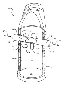
[0031] A first embodiment of a separation system 10 is illustrated in
FIGS. 1-4. As
illustrated in FIGS. 1-3, the system 10 includes a tank 12 having a tank inlet
14 and a tank
outlet 16. The tank 12 is preferably made of concrete but may alternatively be
fabricated in
whole or in parts of metal, plastic, such as fiberglass, or other suitable
materials or a
combination thereof It may be fabricated of an existing manhole or manhole
design and
modified in the manner to be described herein. The tank inlet 14 may be used
to receive
-5-
CA 02652906 2008-11-20
WO 2007/137212
PCT/US2007/069322
untreated liquid from a source. The source may be an upstream transfer system
joined to
the tank inlet 14 by an upstream conduit 18. Alternatively, the tank inlet 14
may receive
the untreated liquid directly, such as from a storm drain. For example, the
upstream
transfer system may include a drainage system from a roadway or a parking lot.
Similarly,
the tank outlet 16 may be used to transfer treated (and untreated) liquid to a
receiver. The
receiver may be a downstream transfer system joined to the tank outlet 16 by a
downstream
conduit 20. The downstream liquid transfer system may include a multi-user
water
treatment plant, natural or artificial surface waters, or subsurface
containment.
[0032] The tank 12 includes a storage chamber 22 and a bypass 24. The
storage
chamber 22 is generally shaped to produce or otherwise allow the rotational
movement of
liquid therein. Although not specifically limited thereto, the storage chamber
22 is
preferably cylindrical in shape. The tank 12 may or may not be of the same
shape. The
illustrated storage chamber 22 includes a bottom 26 and interior sidewalls 28
in a
cylindrical form but may alternatively be in a polygonal form. The storage
chamber 22
further includes an inlet 30 and an outlet 32. The tank 12 may include a lid.
If the tank 12
does include a lid, the storage chamber 22 is typically the space established
by the bottom
26 and interior sidewalls 28 and extends upwardly from the bottom 26 to a
plane at or
below the level of the lid. The tank may include an equalizing line to
equalize pressure
inside and outside the tank 12. The use of an equalizing line allows liquid
within the tank
12 to rise to its highest level of equalization within the separation system
10 including any
inlet and outlet piping. For a tank 12 including an equalizing line, the top
of the storage
chamber 22 is the water surface elevation in the equalizing line, which may
exceed the top
of the bypass 24. Alternatively, for the arrangement of the separation system
10 wherein
the tank 12 has no lid, the height of the interior sidewalls 28 may be
arranged to be above
the highest possible water surface elevation, thereby eliminating the need for
a lid while
allowing the interior space of the storage chamber 22 to remain open for
inspection and
maintenance.
100331 The bypass 24 includes a first inlet 34 at or near the tank inlet
14, a first
outlet 35 in fluid communication with the storage chamber inlet 30, a second
inlet 36 in
fluid communication with the storage chamber outlet 32 and a second outlet 38
at or near
the tank outlet 16. A weir 40 is positioned in the bypass between outlet 35
and inlet 36.
The weir 40 diverts untreated liquid entering the bypass 24 at the first inlet
34 through the
storage chamber inlet 30 into the storage chamber 22. The weir 40 is further
arranged
-6-
CA 02652906 2008-11-20
WO 2007/137212
PCT/US2007/069322
within the bypass 24 to allow excess untreated liquid to pass directly to the
second outlet
38 without passing through storage chamber 22.
[0034] With continuing reference to FIGS. 1-3, the separation system 10
operates
substantially as follows. Untreated liquid 42 enters the tank 12 at tank inlet
14. The
untreated liquid 42 passes into the bypass 24 at first inlet 34. The untreated
liquid 42 then
enters the storage chamber inlet 30 at first bypass outlet 35, which is
located near the first
inlet 34 at or near the invert of the bypass 24. The weir 40 is positioned
downstream of the
storage chamber inlet 30 between the first outlet 35 and the second inlet 36
and acts to
divert untreated liquid 42 into the storage chamber inlet 30 under relatively
low flow rates.
Under relatively high flow rates, the weir 40 diverts a portion of the
untreated liquid 42
into the storage chamber inlet 30 through the first outlet 35 while the
remainder of the
untreated liquid 42 moves directly through the bypass 24 to the tank outlet
16. The amount
of untreated liquid 42 diverted into the storage chamber inlet 30 and the
amount allowed to
bypass the storage chamber 22 are dependent upon the selected height of the
weir 40 within
the bypass 24 and the dimensions of the bypass 24.
[0035] The storage chamber inlet 30 includes a first conduit 44 and a
second
conduit 46. The first conduit 44 is configured to initiate passage of the
untreated liquid 42
into the storage chamber 22. The second conduit 46 is in fluid communication
with the
first conduit 44. It is configured and arranged to divert the untreated liquid
42 into a
tangential flow pattern initially along the interior sidewalls 28 of the
storage chamber 22.
While the storage chamber inlet 30 has been described to include the piping
arrangement
described and shown, it may be another configuration that initiates a flow
pattern within
the storage chamber 22 that applies centrifugal forces to untreated liquid
components,
including contaminants.
[0036] The typical assumption with the operation of any separation system
designed to impart rotational movement of the liquid within a chamber has been
that
particles with a specific gravity greater than that of the liquid will be cast
to the outer walls
due to their angular velocity and the resulting centrifugal forces. Likewise,
particles with a
specific gravity less than that of the liquid should collect at the center.
This is a good
assumption, but is only partially true. The complete description of the
circular or swirling
flow pattern in the chamber, such as storage chamber 22, requires
consideration of pressure
distribution as well as the velocity profile.
-7-
CA 02652906 2008-11-20
WO 2007/137212
PCT/US2007/069322
[0037] With continuing reference to FIGS. 1-3 and with reference to FIGS.
4-5, the
separation system 10 may take advantage of complex fluid mechanics and
particle
dynamics not fully considered in prior fluid treatment systems. The separation
system 10
uses the characteristics of circular flow patterns over a solid surface 26.
Away from the
bottom boundary, flow moves in a circular path with the peripheral velocity
balanced by
lower pressure in the center of rotation. Centrifugal forces produce slight
(secondary)
radially outward flow components. Near the bottom, friction reduces the
circular velocities
and therefore the centrifugal forces, so the low pressure in the center of
rotation causes a
slight (secondary) inward radial flow along the bottom. This secondary flow
transports any
particles to the center. From principles of continuity, the radial inward flow
turns upward
and when this upward flow reaches the vicinity of the surface (another
boundary), it must
flow outward, assisted by centrifugal forces.
[0038] Motion of liquid and particles within the storage chamber 22 can be
best
described by reference to primary and secondary flow patterns. Partially
treated liquid 42 in
a plane near the bottom 26 of the storage chamber 22 will tend to rotate
slower due to the
large frictional influence of the bottom 26. Liquid in a plane near the
liquid's surface will
rotate faster due to the negligible frictional effects and the influence of
the tangential inlet
46. This difference in angular velocity throughout the storage chamber 22
creates a
condition where there is a primary circulation in the direction of tangential
flow from the
second conduit 46, and, a secondary circulation in the meridional plane
(normal to the
primary circulation as shown in Fig 5). The resulting path of a particle is
thus corkscrew
shaped, as shown by flow path 48 of FIG. 4, as it is composed of the primary
rotation about
the axis of the vortex and of the secondary meridional circulation.
[0039] With reference to FIG. 5, the conduits 44 and 46 of storage chamber
inlet 30
may be arranged to cause the liquid to rotate within the storage chamber 22 in
a primary
circulation pattern represented by primary circulation 402. The flow of
primary circulation
402 causes the pressure differential described above with respect to the
discussion of FIG.
4, which causes a secondary circulation pattern represented by secondary
circulation 401.
The flow of secondary circulation 401 is normal to the flow of primary
circulation 402. In
the system as described, the secondary or meridional circulation travels from
the center top
region 52 to the interior sidewalls 28. It then travels down the interior
sidewalls 28 to the
floor 26, across the floor 26 to bottom center region 54, where it begins an
ascent to center
top region 52. Outlet port 33, as placed in the center top position, is
coincident with the up
-8-
CA 02652906 2008-11-20
WO 2007/137212
PCT/US2007/069322
flow of the secondary circulation 401 and is placed such that the secondary
circulation 401
enters outlet port 33 and leaves storage chamber 22 via outlet 32. The outlet
port 33, also
referred to as the storage chamber outlet port, may be viewed as the point at
which water
enters the storage chamber outlet from the storage chamber. Bottom center
region 54 is
where the combination of currents 401 and 402 creates a point of low velocity.
As
secondary circulation 401 makes the turn to ascend and primary circulation 402
is
diminished by friction, in conjunction with the forces and gradients mentioned
above,
particles in the stream aided by gravity tend to create a cone of particles
404 at center
bottom region 54.
[0040] The port 33 may be substantially centered on a vertical axis of
induced
rotational flow (as viewed from the top) within the storage chamber 22. In one
embodiment, the entry port is positioned within the storage chamber at an
elevation,
relative to the chamber bottom, that is between 1/2 X and X, where X is
defined as the no
flow liquid level elevation within the chamber. As used herein, the
terminology "no flow
liquid level elevation" within the chamber is defined as the surface level to
which liquid
within the chamber settles immediately following the cessation of flow through
the unit
and before significant evaporation of any liquid retained within the unit. In
another
embodiment the entry port of the storage chamber outlet is between 2/3 X and
X.
[0041] The treated liquid 56, which was permitted to dwell within the
storage
chamber 22 to enable settling of some particulates therefrom, exits the
storage chamber 22
through the storage chamber outlet 32. The outlet 32 is shown as a pipe
section extending
downwardly from the bypass 24. At one end, the outlet 32 includes an outlet
port 33
located at or below the water surface elevation within the storage chamber 22.
This
arrangement ensures that most floating particulates do not pass into the
outlet 32 yet it is
not so deep that it entrains captured particles. When the volume of liquid
within the
storage chamber 22 exceeds the invert of the bypass 24, the treated liquid 56
passes into the
pipe section and upon reaching the invert, passes into the bypass 24 via the
second inlet 36
of the bypass 24. The treated liquid 56 then continues to the downstream
passageway of
the bypass 24. It exits the bypass at bypass outlet 38, which may be, or may
not be near
tank outlet 16.
[0042] The separation system 10 may be fabricated with the interior
sidewalls 28 of
the storage chamber 22 arranged to enhance or disrupt the liquid flow pattern.
For
example, the interior sidewalls 28 may be configured with a corrugated or
helical pattern in
-9-
CA 02652906 2008-11-20
WO 2007/137212
PCT/US2007/069322
a downward spiraling configuration. Such a configuration would enhance flow
smoothing
and direction. Alternatively, the corrugated or helical pattern arranged in an
upwardly
spiraling configuration would cause flow turbulence and therefore increasing
friction and
pressure differentials at the interior sidewalls 28. The bypass 24 may be
cylindrical or
other selectable shape, such as a trough-shape that is open at the top. It may
be fabricated
of any material of interest. For example, it may be fabricated of concrete,
metal, plastic, a
composite or a combination thereof. The bypass 24 may be sized as a function
of desired
flow patterns, expected flow volumes, and desired bypass rates. It may be
fabricated with
an interior arranged to smooth or disrupt flow patterns. For example, it may
be formed
with an interior that is corrugated or to have a helical pattern it may also
include one or
more baffles.
[0043] In one embodiment, the bypass may be formed as an expandable
assembly
that has a retracted configuration in which the end to end length of the
bypass is less than
the diameter of the tank, allowing the bypass to be dropped into the top of
the tank. When
the ends of the bypass align with the tank inlet and outlet, the bypass is
expanded (i.e.,
pulled apart so that the ends of the bypass move into the tank inlet and
outlet and can be
fastened thereto. In one implementation of this embodiment the bypass assembly
may be
formed of a central portion and two end portions, with both end portions
retractable inward
relative to the end portions for the purpose of insertion of the assembly in a
tank.
[0044] The weir 40 may be curved or flat. It may be fabricated of any
material of
interest. For example, it may be fabricated of concrete, metal, plastic, a
composite or a
combination thereof. It may form a permanent part of the bypass 24 or be
removably
attachable to the invert thereof Either or both of its positions with respect
to the storage
chamber inlet 30 and its dimensions within the bypass 24 may be varied as a
function of
flow volumes to be diverted and to be bypassed. The weir 40 may have a wall
height such
that its top exceeds the height of the top of the tank inlet 14. The weir 40
may include
surface variations, such as a corrugated or helical pattern. The weir may be
cut to allow
varying flows to pass for example a "V" or "U" shape cut into the weir to
allow graduated
flows. The storage chamber inlet 30 and the storage chamber outlet 32 may be
conduits or
pipes as shown. Alternatively, they may form another transfer mechanism. They
may be
fabricated of the same or different materials as the material used to make the
bypass 24.
The storage chamber inlet 30 and the storage chamber outlet 32 may be unitary
pieces of
-10-
CA 02652906 2008-11-20
WO 2007/137212
PCT/US2007/069322
the bypass 24, or they may be separate pieces permanently or removably
attached to the
bypass 24.
[0045] A second embodiment of a separation system 100 is shown in FIG. 6.
The
system 100 includes a tank 102 having a tank inlet 104 and a tank outlet 106.
The tank 102
is preferably made of concrete but may alternatively be fabricated in whole or
in parts of
metal, plastic, such as fiberglass, or other suitable materials or a
combination thereof. It
may be fabricated of an existing manhole. The tank inlet 104 may be used to
receive
untreated liquid from a source. The source may be an upstream transfer system
joined to
the tank inlet 104 by an upstream conduit. Alternatively, the tank inlet 104
may receive the
untreated liquid directly, such as from a storm drain. For example, the
upstream transfer
system may include a drainage system from a roadway or a parking lot.
Similarly, the
tank outlet 106 may be used to transfer treated liquid to a receiver. The
receiver may be a
downstream transfer system joined to the tank outlet 106 by a downstream
conduit 110.
The downstream transfer system may include a multi-user water treatment plant,
natural or
artificial surface waters, or subsurface containment.
[0046] The tank 102 includes a storage chamber 112. The storage chamber
112 is
generally shaped to produce or otherwise allow the rotational movement of
liquid therein.
Although not specifically limited thereto, the storage chamber 112 is
preferably cylindrical
in shape. The tank 102 may or may not be of the same shape. The storage
chamber 112
includes a bottom 114 and interior sidewalls 116 in a cylindrical form but may
alternatively
be in a polygonal form. The storage chamber 112 further includes an inlet 118
and an
outlet 120. The tank 102 may include a lid or a grate as an entrance. The tank
102
optionally arranged with a lid may include the equalizing line referred to
above with regard
to tank 12 of separation system 10. In the illustrated embodiment, the storage
chamber 112
is the space established by the bottom 114 and interior sidewalls 116 and
extends upwardly
from the bottom 114 to a plane at or below the level of the lid or the grate.
Alternatively,
the height of the interior sidewalls 116 may be arranged to be above the
highest possible
water surface elevation, thereby eliminating the need for a lid while allowing
the interior
space of the storage chamber 112 to remain open for inspection and
maintenance.
[0047] The storage chamber inlet 118 is arranged to receive untreated
liquid 42 and
includes a first inlet conduit 122 and a second inlet conduit 124. The first
inlet conduit 122
is, a pipe vertically oriented within the tank 102 when the tank 102 is in an
upright
operational position and configured to initiate passage of the untreated
liquid 42 into the
-11-
CA 02652906 2008-11-20
WO 2007/137212
PCT/US2007/069322
storage chamber 112. That is, it is at or about perpendicular with respect to
the plane
defined by the bottom 114 of the storage chamber 112. The second inlet conduit
124 is,
effectively, a second pipe leg in fluid communication with the first inlet
conduit 122. It is
configured and arranged to divert the untreated liquid 42 into a tangential
flow pattern
initially along the interior sidewalls 116 of the storage chamber 112. While
the storage
chamber inlet 118 has been described to include the arrangement of second
inlet conduit
124 in relation to first inlet conduit 122 as shown, it may be another
configuration that
initiates a flow pattern within the storage chamber 112 that applies
centrifugal forces to
untreated liquid components, including contaminants.
[0048] As with the embodiment of the separation system 10 described with
respect
to FIGS. 1-4, the outlet 120 from the storage chamber 112 of system 100 of
FIG. 6 is
positioned where it enhances the desired flow pattern and where turbulence may
be
minimized. That position is typically at or near center top region 126.
Treated liquid 56
reaching that position has had the greatest dwell time within the storage
chamber 112. That
is, the outlet 120 includes an opening positioned substantially centered on a
vertical axis
about which fluid rotation occurs, which in the illustrated embodiment also
happens to the
center axis of the storage chamber 112. More specifically, the outlet 120
includes a first
outlet conduit 128 and a second outlet conduit 130, each represented as a pipe
section in
FIG. 6. The second outlet conduit 130 is arranged to enable the passage of
liquid out of the
storage chamber 112. It may be at or about parallel to the bottom 114 of the
storage
chamber 112, but is not limited to that arrangement.
[0049] The first outlet conduit 128 extends downwardly from the second
conduit
outlet 130 and includes a storage chamber outlet port 132 positioned within
the storage
chamber 112 at or below the water surface elevation within the storage chamber
112. This
arrangement ensures that most floating particulates do not pass into the
outlet 120. When
the volume of liquid within the storage chamber 112 exceeds the invert of the
second outlet
conduit 130, treated liquid 56 passes into the second outlet conduit 130 from
the first outlet
conduit 128. The treated liquid 56 then continues through the downstream
passageway
established by the second outlet conduit 130. It exits the second outlet
conduit 130 at 134,
which may be, or may not be near tank outlet 106, and then exits the tank 102
at tank outlet
106.
[0050] The separation system 100 may be fabricated with the interior
sidewalls 116
of the storage chamber 112 arranged to enhance or disrupt the flow pattern.
For example,
-12-
CA 02652906 2008-11-20
WO 2007/137212
PCT/US2007/069322
the interior sidewalls 116 may be configured with a corrugated or helical
pattern in a
downward spiraling configuration. Such a configuration would enhance flow
smoothing
and direction. Alternatively, the corrugated or helical pattern arranged in an
upwardly
spiraling configuration would cause flow turbulence which would increase
friction and
pressure differentials at the interior sidewalls 116. The tank 102 may include
one or more
baffles.
[0051] A third embodiment of the separation system 200 is shown in FIG. 7.
The
system 200 includes a tank 202 having a tank inlet 204 and a tank outlet 206.
The tank 202
is preferably made of concrete but may alternatively be fabricated in whole or
in parts of
metal, plastic, such as fiberglass, or other suitable materials or a
combination thereof. It
may be fabricated of an existing manhole including, for example, manhole
transition 300.
The tank inlet 204 may be used to receive untreated liquid from a source. The
source may
be an upstream transfer system joined to the tank inlet 204 by an upstream
conduit 208 or
other source as described above. Similarly, the tank outlet 206 may be used to
transfer
treated liquid to a receiver. The receiver may be a downstream liquid transfer
system
joined to the tank outlet 206 by a downstream conduit 210. The downstream
liquid transfer
system may include a multi-user water treatment plant, natural or artificial
surface waters,
or subsurface containment.
[0052] The tank 202 may include a storage chamber 212. The storage chamber
212
is generally shaped to produce or otherwise allow the rotational movement of
liquid
therein. Although not specifically limited thereto, the storage chamber 212 is
preferably
cylindrical in shape. The tank 202 may or may not be of the same shape. In the
illustrated
embodiment, the storage chamber 212 includes a bottom 214 and interior
sidewalls 216 in
a cylindrical form but may alternatively be in a polygonal form. The storage
chamber 212
further includes an inlet 218 and an outlet 220. The tank 202 may include a
lid. The tank
202 optionally arranged with a lid may include the equalizing line referred to
above with
regard to tank 12 of separation system 10. The storage chamber 212 is the
space
established by the bottom 214 and interior sidewalls 216 and extends upwardly
from the
bottom 214 to a plane at or below the level of the lid. Alternatively, the
height of the
interior sidewalls 216 may be arranged to be above the highest possible water
surface
elevation, thereby eliminating the need for a lid while allowing the interior
space of the
storage chamber 212 open for inspection and maintenance.
-13-
CA 02652906 2008-11-20
WO 2007/137212
PCT/US2007/069322
[0053] The storage chamber inlet 218 is arranged to receive untreated
liquid 42 and
includes a first inlet conduit 222 and a second inlet conduit 224. The first
inlet conduit 222
is a pipe positioned as a side inlet structure, generally arranged to be at or
near parallel with
the plane defined by the bottom 214 of the storage chamber 212, but not
limited thereto.
The first inlet conduit 222 is configured to initiate passage of the untreated
liquid 42 into
the storage chamber 212. The second inlet conduit 224 is, effectively, a
second pipe leg in
fluid communication with the first inlet conduit 222. It is configured and
arranged to divert
the untreated liquid 42 into a tangential flow pattern initially along the
interior sidewalls
216 of the storage chamber 212. While the storage chamber inlet 218 has been
described
to include the arrangement of second inlet conduit 224 in relation to first
inlet conduit 222
as shown, it may be another configuration that initiates a flow pattern within
the storage
chamber 212 that applies centrifugal forces to untreated liquid components,
including
contaminants.
[0054] As with the embodiment of the separation system 10 described with
respect
to FIGS. 1-4, the outlet 220 from the storage chamber 212 of system 200 of
FIG. 7 is
positioned where it enhances the secondary currents and where it causes
minimal
disruption of the desired flow pattern and where turbulence is minimized. That
position is
at or near center top region 226. Treated liquid 56 reaching that position has
had the
greatest dwell time within the storage chamber 212. That is, the outlet 220
includes an
opening positioned about at the center axis of rotational flow within the
storage chamber
212. More specifically, the outlet 220 includes a first outlet conduit 228 and
a second
outlet conduit 230, each represented as a pipe section in FIG. 7. The second
outlet conduit
230 is arranged to enable the passage of liquid out of the storage chamber
212. It may be at
or about parallel to the bottom 214 of the storage chamber 212, but is not
limited to that
arrangement.
[0055] The first outlet conduit 228 extends downwardly from the second
conduit
outlet 230 and includes a storage chamber outlet port 232 positioned within
the storage
chamber 212 at or below the water surface elevation within the storage chamber
212. This
arrangement ensures that most floating particulates do not pass into the
outlet 220. When
the volume of liquid within the storage chamber 212 exceeds the invert of the
second outlet
conduit 230, treated liquid 56 passes into the second outlet conduit 230 from
the first outlet
conduit 228. The treated liquid 56 then continues through the downstream
passageway
established by the second outlet conduit 230. It exits the second outlet
conduit 230 at 234,
-14-
CA 02652906 2008-11-20
WO 2007/137212
PCT/US2007/069322
which may be, or may not be near tank outlet 206, and then exits the tank 202
at tank outlet
206.
[0056] The separation system 200 may be fabricated with the interior
sidewalls 216
of the storage chamber 212 arranged to enhance or disrupt the flow pattern.
For example,
the interior sidewalls 216 may be configured with a corrugated or helical
pattern in a
downward spiraling configuration. Such a configuration would enhance flow
smoothing
and direction. Alternatively, the corrugated or helical pattern arranged in an
upwardly
spiraling configuration would cause flow turbulence which would increase
friction and
pressure differentials at the wall. It may be fabricated of any material of
interest. For
example, it may be fabricated of concrete, metal, plastic, a composite or a
combination
thereof. The tank 202 may include one or more baffles. Likewise other
illustrated
embodiments may include baffles.
[0057] A fourth embodiment of a separation system 400 is shown in FIGS. 8-
10.
The system 400 includes a tank 402 having a tank inlet 404 and a tank outlet
406. The tank
402 is preferably made of concrete but may alternatively be fabricated in
whole or in parts
of metal, plastic, such as fiberglass, or other suitable materials or a
combination thereof. It
may be fabricated of an existing manhole. The tank inlet 404 may be used to
receive
untreated liquid from a source. The source may be an upstream transfer system
joined to
the tank inlet 404 by an upstream conduit 408 or other source as described
above.
Similarly, the tank outlet 406 may be used to transfer treated liquid to a
receiver. The
receiver may be a downstream transfer system joined to the tank outlet 406 by
a
downstream conduit 410. The downstream transfer system may include a multi-
user water
treatment plant, natural or artificial surface waters, or subsurface
containment.
[0058] The tank 402 includes a storage chamber 412 and a bypass 414. The
storage
chamber 412 is generally shaped to produce or otherwise allow the rotational
movement of
liquid therein. Although not specifically limited thereto, the storage chamber
412 is
preferably cylindrical in shape. The tank 402 may or may not be of the same
shape. The
storage chamber 412 includes a bottom 416 and interior sidewalls 418 in a
cylindrical form
but may alternatively be in a polygonal form. The storage chamber 412 further
includes an
inlet 420 and an outlet 422. The tank 402 may include a lid or a grate as an
alternative
entrance. The tank 402 optionally arranged with a lid may include the
equalizing line
referred to above with regard to tank 12 of separation system 10. The storage
chamber 412
is the space established by the bottom 416 and interior sidewalls 418 and
extends upwardly
-15-
CA 02652906 2008-11-20
WO 2007/137212
PCT/US2007/069322
from the bottom 416 to a plane at or below the level of the optional lid or
the equalizing
line. It may exceed the height of the bypass 414. Alternatively, the height of
the interior
sidewalls 418 may be arranged to be above the highest possible water surface
elevation,
thereby eliminating the need for a lid while allowing the interior space of
the storage
chamber 412 open for inspection and maintenance.
[0059] The bypass 414 includes a first inlet 424 at or near the tank inlet
404, a first
outlet that is the inlet 420 of the storage chamber 412 to establish direct
fluid
communication with the storage chamber 412. The bypass 414 also includes a
second inlet
that is the outlet 422 of the storage chamber 412 to establish direct fluid
communication
with the storage chamber 412. The bypass 414 further includes a second outlet
426 at or
near the tank outlet 406. The bypass 414 also includes a weir 428. The weir
428 diverts
untreated liquid entering the bypass 414 at the first inlet 424 through the
storage chamber
inlet 420 into the storage chamber 412. The weir 428 is further arranged
within the bypass
414 to allow excess untreated liquid to pass directly to the second outlet 426
without
passing through the storage chamber 412. The bypass 414 may be substantially
or
completely closed except for the described inlets and outlets. An offset
difference between
the invert of 410 and the invert of 414 causes a normal or nominal water
surface elevation
in the system at least equal to the elevation of the invert of 410. This
arrangement ensures
that most floating particulates do not pass into outlet 422.
[0060] The separation system 400 operates substantially as follows.
Untreated
liquid 42 enters the tank 402 at tank inlet 404. The untreated liquid 42
passes into the
bypass 414 at first inlet 424. The untreated liquid 42 then enters the storage
chamber inlet
420, which is located near the first inlet 424 at or above the invert of the
bypass 414. The
weir 428 is positioned downstream of the storage chamber inlet 420 between the
storage
chamber inlet 420 and the storage chamber outlet 422. It acts to divert
untreated liquid 42
into the storage chamber inlet 420 under relatively low flow rates. Under
relatively high
flow rates, the weir 428 diverts a portion of the untreated liquid 42 into the
storage
chamber 412 through storage chamber inlet 420 while the remainder of the
untreated liquid
42 moves directly through the bypass 414 to the tank outlet 406. The amount of
untreated
liquid 42 diverted into the storage chamber 412 and the amount allowed to
bypass the
storage chamber 412 are dependent upon the selected height of the weir 428
within the
bypass 414 and the dimensions of the bypass 414.
-16-
CA 02652906 2008-11-20
WO 2007/137212
PCT/US2007/069322
[0061] It can be seen from FIGS. 8-10 that the separation system 400
differs from
the separation system 10 in that the storage chamber inlet 420 and the storage
chamber
outlet 422 are ports of the bypass 414 rather than conduit arrangements
connected to the
bypass. The storage chamber inlet 420 is preferably arranged and configured to
divert the
untreated liquid 42 into a tangential flow pattern initially along the
interior sidewalls 418 of
the storage chamber 412. For example, the storage chamber inlet 420 may be a
port of the
bypass 414 arranged to cause the untreated liquid 42 entering the bypass 414
to be directed
at an angle change of about 90 degrees. Further, the port of the bypass 414 as
the storage
chamber inlet 420 may be round or it may be shaped as shown in FIG. 10 such
that flow
turbulence is reduced as the untreated liquid 42 exits the bypass 414.
[0062] As with the embodiment of the separation system 10 described with
respect
to FIGS. 1-4, the outlet 422 from the storage chamber 412 of system 400 of
FIGS. 8-10 is
positioned where it enhances the secondary currents, where it causes little
disruption of the
desired flow pattern and where turbulence may be minimized. That position is
at or near
center top region 434. Treated liquid 56 reaching that position has had the
greatest dwell
time within the storage chamber 412 as previously noted. That is, the storage
chamber
outlet 422 is a port of the bypass 414 located about at the center axis of the
storage
chamber 412 at or below the water surface elevation within the storage chamber
412.
When the volume of liquid within the storage chamber 412 exceeds the level of
the storage
chamber outlet 422, treated liquid 56 passes into the bypass 414 and exits the
bypass 414
through second outlet 426.
[0063] The separation system 400 may be fabricated with the interior
sidewalls 418
of the storage chamber 412 arranged to enhance or disrupt the liquid flow
pattern. For
example, the interior sidewalls 418 may be configured with a corrugated or
helical pattern
in a downward spiraling configuration. Such a configuration would enhance flow
smoothing and direction. Alternatively, the corrugated or helical pattern
arranged in an
upwardly spiraling configuration would cause flow turbulence which would
increase
friction and pressure differentials at the wall. It may be fabricated of any
material of
interest. For example, it may be fabricated of concrete, metal, plastic, a
composite or a
combination thereof.
[0064] The tank 402 may include one or more baffles. For example, as shown
in
FIG. 11, the tank 402 includes baffle 430 arranged to be either permanently or
removably
attached to, and extend downwardly from, the bypass 414 to a location within
the storage
-17-
CA 02652906 2008-11-20
WO 2007/137212
PCT/US2007/069322
chamber 412 above the bottom 416. The baffle 430 is preferably a cylinder or
other shape
suitable to be attached to the bypass 414 in an arrangement to partially or
completely
surround the storage chamber outlet 422. The baffle 430 includes opening 432
to allow
liquid within the storage chamber 412 to pass to the storage chamber outlet
422. The baffle
430 is arranged to block at least a portion of floating particulates from
entering the bypass
414 through the storage chamber outlet 422. The baffle may be positioned and
oriented
within the expected flow pattern within the storage chamber 412 at a location
causing
minimal disruption of that flow pattern. The preferred location for that
purpose is upper
center region 434 of the storage chamber 412.
[0065] The baffle 430 may be fabricated with either or both of the
interior and
exterior sidewalls arranged to enhance or disrupt the liquid flow pattern. For
example,
either or both of the sidewalls may be configured with a corrugated or helical
pattern in a
downward spiraling configuration. Such a configuration would enhance flow
smoothing
and direction. Alternatively, the corrugated or helical pattern arranged in an
upwardly
spiraling configuration would cause flow turbulence which would increase
friction and
pressure differentials at the wall . It may be fabricated of any material of
interest. For
example, it may be fabricated of concrete, metal, plastic, a composite or a
combination
thereof
[0066] Referring again to Figs. 1-4, the illustrated embodiment shows an
orientation in which the swirling flow within the storage chamber is created
in a clockwise
direction (as viewed from the top of the unit). Alternatively, the unit could
be constructed
with conduit 46 facing the opposite direction to generate a counterclockwise
flow (as
viewed from the top of the unit). Preliminary testing has suggested that,
depending upon
the exact size and configuration of a unit, some variation in effectiveness
may occur as
between clockwise and counterclockwise rotational flow, perhaps due to the
vortex induced
in the piping that leads from the bypass to the storage chamber. However, in
certain
configurations it appears that the selection of clockwise or counterclockwise
rotational
flow in the storage chamber may not have any significant impact on the
effectiveness of the
unit.
[0067] A filter screen or other filter arrangement may also be associated
with any
one of the outlets 32, 120, 220 or 422 of the various embodiments to aid in
retaining certain
floatables and/or solids in the storage chamber. Further, in those embodiments
including a
bypass, a head equalization baffle may be incorporated into the bypass
downstream of the
-18-
CA 02652906 2008-11-20
WO 2007/137212
PCT/US2007/069322
storage chamber outlet causing a back pressure that slows flow down through
the treatment
path as described in U.S. Patent No. 6,991,114.
[0068] Referring now to Figs. 12-14, an alternative assembly
configuration is
shown in which bypass mount frames 500 and 502 are connected to the tank
sidewalls
respectively adjacent the inlet and outlet of the tank. Each bypass mount
frame may
include curved portions 504 and 506 for matching with the curved tank
sidewalls. Side
portions 508 extend upward along the side edges of the inlet or outlet. The
portions 504,
506 and 508 may be used to secure the frames to the tank via suitable
fastening means
(e.g., concrete anchors, screws or other rigid fasteners depending upon the
material of the
tank and frame, or an epoxy or other liquid/chemical fastener material). Each
mount frame
includes respective side flanges 510 and bottom support surface 512 that
define a u-shaped
receiving slot 514 that is open at the top. The mount frames may be readily
formed of a
sheet metal material, such as stainless steel or aluminium, but other
materials could be used
as well. The bypass structure 520 has a U-shaped configuration similar to that
of the frame
slots 514 so that the ends of the bypass structure can be received in the
slots 514. In this
manner the mount frames support the bypass structure within the tank. The
bypass
structure may be pre-assembled with pipes 522 and 524 to form the storage
chamber inlet
and outlet respectively, and the pre-assembled bypass structure may be dropped
into the
tank once the mount frames have been installed. Pipe 522 may have an L-shaped
configuration to produce the desired flow pattern previously described. The
end portions
of the bypass sidewalls 526 and 528 may be secured to the flanges 510 of the
mount frames
using suitable fastening means (e.g., screws, bolts, welding, or an epoxy or
other
liquid/chemical fastener material depending upon the materials used. In one
implementation, the bypass structure is formed by bending a metal sheet into
the u-shaped
configuration. As best seen in Fig. 13, the upper end of each sidewall 526 and
528 may be
bent inward (or outward) to form a lip providing structural rigidity. Multiple
pieces of
sheet metal bent and welded to form the bypass could also be used. Other
materials could
also be used. As most clearly seen in Fig. 14, the internal space of the
bypass structure
may include weir 530 and head equalization baffle 532 on opposite sides of the
storage
chamber outlet defined by pipe 524. Moreover, the bypass sidewall 526 may
include a
secondary storage chamber spillover inlet 534. The storage chamber spillover
inlet 534 is
positioned to allow floatables such as oil to enter the storage chamber
without having to
-19-
CA 02652906 2008-11-20
WO 2007/137212
PCT/US2007/069322
travel through the storage chamber inlet 522, and before such floatables pass
over the weir
530.
[0069] Referring now to Figs. 15-18, a variation having a grate-type inlet
540 at the
top is shown. The grate-inlet is formed by a grate 542, frame 544, frame
insert 546 and
flow directing box insert 548. The frame 544 is positioned around a tank inlet
550 in the
top wall 552 of the tank, and includes an internal ledge 554 along each side
for receiving
and supporting a corresponding externally extending flange 556 along each side
of the
frame insert 546. The frame insert also includes a through opening 558 that
aligns with the
opening 550. Bottom wall 560 of the frame insert 546 may also rest upon the
top wall of
the tank when placed into the frame 544. The flow directing box insert 548
includes an
upper flange 562 circumscribing a portion of the box inlet 564, which is
rectangular-shaped
in the illustrated embodiment. Sidewalls 566 extend down from the flange 562
to form the
box structure that includes a partial bottom wall 568. The bottom wall does
not extend the
full length of the box-shape, thereby leaving a flow gap 570 that will permit
incoming
stormwater to flow into the tank. The box insert 548 is mounted to the frame
insert 540 so
that incoming flow of stormwater is directed to the desired location within
the tank,
typically into the bypass at the upstream side of the weir as shown by the
flow arrows 572
in Fig. 15. An insert positioning bracket 574 is provided for assuring that
the desired
orientation and position of the flow gap 570 is maintained. Specifically, the
positioning
bracket 574 is secured (e.g., by screws or other fastening means) to the inner
edge of frame
insert bottom wall 560 at a specific location around the periphery of opening
558. The
bracket 574 is sized to fit within the open end of box inlet 564 and includes
upwardly
extending fingers 576 that are configured to interfere with the flange 562 if
the box insert is
not oriented with the open end of box inlet properly aligned with the bracket
574. The
fingers 576 also prevent rotation of the box insert when the box insert is
seated in the frame
insert 546.
[0070] While the embodiment of Figs. 15-18 show a tank unit with both a
sidewall
inlet and a top wall grate inlet, it is recognized that some applications
could utilize only the
top wall grate inlet.
[0071] While certain, desired flow patterns are described with respect to
various of
the embodiments above, it is recognized that variations may occur.
Accordingly, the
claims provided below are not to be read as limited to any specific flow
pattern unless
expressly stated therein.
-20-
CA 02652906 2008-11-20
WO 2007/137212
PCT/US2007/069322
[0072] What is claimed is:
-21-