Note: Descriptions are shown in the official language in which they were submitted.
CA 02653113 2008-11-19
Method for the highly precise regulation of load-variable heat sources or heat
sinks, and device for controlling the temperature of a dynamic heat source,
especially pump diodes for solid-state lasers
The invention relates to a method for the highly precise regulation of load-
variable heat sources or heat sinks, and to a device for controlling the
temperature of a dynamic heat source, especially of pump diodes for solid-
state
lasers according to the preamble of the independent claims.
According to the prior art, exclusively the temperature of the forward flow is
kept constant by a regulation device in commercially available cooling or
heating devices with liquid media. The return temperature and the flow through
the connected load are not taken into account. When the thermal load changes,
the heating or cooling performance of the system is adapted to the load
conditions by the provided regulation only after a prolonged period of time,
i.e.
when the coolant within a reservoir has warmed up to such a degree that the
forward flow temperature changes. This results in a comparatively slow
reaction of the system to an alternating heat introduction by the heat source
or
heat sink to be temperature-controlled.
Furthermore, in the solutions of the state of the art, the actual temperature
depends on the load conditions in that in real systems, the heat source or
heat
sink is not temperature-controlled directly by the cooling medium itself, but
additional heat transfer resistances are present between the heat source/sink
and the temperature-controlled media. Due to that, the temperature at the heat
source or heat sink will change in a load-dependent manner while the flow
temperature is constant.
Devices for controlling the temperature of pump diodes for solid-state lasers
belong to the known state of the art. In such known laser cooling systems
usually only the forward flow temperature is regulated or pre-defined as a set
value. The return temperature thereby depends on the input quantity of heat
and the heat flow, i.e. on the coolant flowing per unit of time. Further
dependencies occur due to cross-sectional changes, e.g. by depositions in the
coolant circuit.
CA 02653113 2008-11-19
2
In solid-state lasers pumped by semiconductor diodes, a precise adaptation of
the emission wavelength of the pump diodes to the pump bands of the laser
crystal is one of the decisive parameters for optimizing the overall laser
efficiency. For example, a pump band from 805 nm to 809 nm of the Nd:YAG
crystal is in the range of the emission wavelength of gallium arsenide diodes,
the highest efficiency of the laser system being reached at a pump wavelength
of 808 nm.
Since the emitted wavelength in pump diodes displaces by about 0.25 nm/K as
a function of temperature, a precise control of the emitter temperature is
indispensable for a high output constancy of the Nd:YAG laser.
The dependence of the wavelength on the temperature expresses itself, for
example, in that a laser diode having a factory specification of 810 nm / 25 C
actually reaches its optimum wavelength range for excitation of 808 nm at
17 C. Hence, it is necessary to pre-define and set the precise pump diode
temperature for a maximum efficiency by an accurately regulated cooling
tailored to demand.
Further difficulties with respect to the desired precise pump diode
temperature
setting reside in that the used laser diodes basically exhibit different diode-
specific wavelengths as a consequence of variances during the manufacturing
process. If several of such laser diodes are used for pumping, the pumping
light will also contain spectral wavelength portions which only can be used
with
a low efficiency for exciting the laser crystal.
From the above-mentioned it is therefore an object of the invention to propose
an improved method for the highly precise regulation of load-variable heat
sources or heat sinks, and an associated device for controlling the
temperature, wherein a high regulation accuracy is ensured with a
corresponding quick response characteristic so that an optimized heating and
cooling management can be reached in toto.
CA 02653113 2008-11-19
3
The achievement of the object of the invention is realized by a method
according to the teaching of claim 1 and a device according to the feature
combination as per claim 4, the subclaims representing at least appropriate
embodiments and improvements.
In a first method-related realization of the teaching according to the
invention, a
calculated mean value of the forward flow temperature and the return flow
temperature is used as an actual value for regulation. Hereby, the
stabilisation
of the heat source may be improved without additional information on the type
of thermal load and the heat quantity to be dissipated.
An advantage arises from the fact that the mean reference temperature
TM ='/2 =(Tv + TR) for the heat flow QL is maintained at a constant value
irrespective of the heat quantity to be dissipated. Thus, an increase in the
heat
flow to the actual cooling device will automatically result in a decrease of
the
forward flow temperature. Since during a change of load the return flow
temperature will change faster than the reservoir temperature, the regulation,
as well, will respond faster in the desired manner. In the proposed mean value
regulation, the heat transfer resistance between the heat source (e.g. a laser
diode) and a heat sink (e.g. the cooling water) is not yet taken into account.
This means in a real application that the temperature of the heat source will
still
increase linearly and as a function of load with an increasing heat flow. If
the
heat resistance between the heat source and the heat sink is known, then this
may be taken into account according to the method when the heat flow, i.e. the
cooling power into the cooler is subjected to a metrological detection.
In a further method-related idea, a mean value regulation is used taking into
account the actual heat flow through the temperature-controlling device.
Using a flow sensor and from the measurement values of forward flow
temperature Tv and return flow temperature TR, the cooling power (heat flow)
QK =(Tv - TR) = Vdt = k of the cooling device may be determined. Here, Vdt
represents the volume flow.
CA 02653113 2008-11-19
4
Since in the stationary case, the sum of all heat flows in a closed system
will be
zero with unchanging temperatures, it is considered that with the radiation
losses Qs being neglected, the heat efficiency output by the heat source will
be
equal to the cooling efficiency of the cooling device, i.e. QK = QL. A
temperature
difference in proportion to the heat flow hence results for a constant thermal
conductance resistance RWL between the heat source and the cooling circuit.
As a reversal conclusion, a correction value for the mean reference
temperature TM may be calculated for each heat flow with consideration of the
thermal conductance resistance RWL, and this mean reference temperature TM
has to be set so as to maintain the temperature of the load TQ, s constant
under
the measured load conditions. If in practice it is not possible to determine
the
heat resistance directly between heat source and heat sink, then, due to the
linear correlations, the heat transfer resistance needed for the model
calculation may be determined empirically by manually optimizing the system at
two operating points, e.g. at a load of 40% and at a load of 90%.
A further method-related realization of the invention consists in the mean
value
regulation with consideration of the actual heat flow by the temperature-
controlling device and the disturbance variable Qs.
In the case of a laser diode to be temperature-controlled, it is necessary,
with
great demands on the regulation accuracy, that the heat flow through the
irradiation of electromagnetic radiation be taken into account in the model.
The
heat flow due to optical irradiation namely may amount up to 40% of the input
electrical power. This consideration of characteristics may either take place
in
the model on a computational basis, or there is the possibility to detect the
optical radiation power as an additional parameter on a metrological basis.
Here, the advantage arises that an ageing of the laser diode may be
compensated automatically, since the efficiency of the diode will degrade with
ageing and the relation between the electrical input power and the optical
output power will shift. With a corresponding characteristic representation
this
will be equivalent to a decrease of the straight-line gradient.
CA 02653113 2008-11-19
The method-related, as well as the basic idea of the invention embodied in the
device may be summarized at this point in that for a precise regulation of a
laser beam source temperature the return flow temperature is detected as well
as the cooling circuit forward flow temperature in order to build up a mean
5 value regulation on this basis, which optionally takes into account the
actual
heat flow and/or several disturbance variables in the regulation on a model-
basis. This may be realized by means of correction factors intended to shift
the
mentioned mean value in proportion to the difference of the forward and return
flows.
As a result of examinations conducted, it surprisingly turned out, that the
detection of absolute temperatures in the forward and return flows is
primarily
not important, but rather the gradient, i.e. the temperature difference
between
the forward and return flows, is important. If the gradients present here are
detected during the operation of the laser, it is possible to react
extraordinarily
fast on a control engineering basis, so that the temperature variance across a
spatial expansion of an existing cooling block on which a pre-defined number
of
pump diodes are located, may be maintained low compared to the state of the
art. Thereby, the possibility results in the end that individual pump diodes
be
maintained in a temperature regime which is suited for an optimal excitation,
in
particular for high-power applications. The device for controlling the
temperature of pump diodes for a solid-state laser, which are arranged on a
cooling block, accordingly possesses a forward flow temperature measuring
device in the pump diode coolant circuit, and in addition a temperature
measuring device arranged in the return flow. As an option, a through-flow
measuring device for the coolant may be used to determine the actual heat
flow.
The forward and return flow measuring devices are connected to a computing
unit, which even may be analog, and which performs the already mentioned
mean value calculation in order to determine a refrigerating capacity set
value
transmitted to corresponding switching devices or valves for the regulation of
the power, which are present in the coolant circuit.
CA 02653113 2008-11-19
6
The forward flow and/or return flow temperature measuring device may be
configured in one embodiment as a temperature difference sensor.
The coolant circuit may be provided with a flow sensor for determining the
heat
flow from the temperature difference and the forward or return flow
temperature. The heat transition between the pump diodes and the material of
a pump diode cooling block is determined on a refrigerant-specific basis, and
this value is input into the computing unit as a correction factor K1. The
diode-
specific heat irradiation over the respective pump performance is likewise
determined. This dependency is then input into the computing unit as a second
correction value K2 or as a correction function f(K2).
As a function of the respective current mean values and the power turnover
directly resulting from these, the computing unit will transmit a control
signal to
the circulating pump in the coolant circuit.
Optionally, there is the possibility to provide a heating device in a coolant
reservoir present within the coolant circuit so as to request a nearly
constant
cooling power from the coolant circuit even at per se different requirements
originating from the actual laser.
In the following, the invention will be explained in more detail in terms of
exemplary embodiments and with reference to figures.
Fig. 1 shows a schematic representation for the understanding of the
model view of the regulation method according to the invention,
and
Fig. 2 shows a schematic representation of a device for controlling the
temperature, comprising a pump diode coolant circuit (water
circuit) and a cooling circuit.
CA 02653113 2008-11-19
7
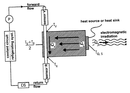
The representation according to Fig. 1, namely the model of a fluid-controlled
system with radiation losses, shows a heat source or heat sink with outlined
electromagnetic radiation.
This heat source may comprise one laser diode or a set of laser diodes. TQ,S
designates the actual temperature of the heat source or heat sink. Qs
represents the heat flow due to electromagnet irradiation or radiation and
further disturbance variables. QL refers to the heat flow to / from the
temperature-controlling medium, and Qk refers to the heat flow of the cooler.
Corresponding temperature sensors are present in the forward and return
flows.
The following physical correlations apply as far as the model representation
is
concerned:
The sum of all heat flows of the entire system is zero in the static case;
i.e.
QK + QL+Qs=0.
The heat flow of the cooler circuit is determined by the product of the
temperature difference Tv - TR and the flow rate of the medium, as well as the
heat capacity k of the medium, i.e. QK - (Tv - TR) = Vdt = k.
The heat flow QL from or into the heat sink is proportional to the temperature
difference TQs - TM and the thermal conductivity resistance RWL between heat
source / heat sink and the temperature-controlling circuit, i.e. QL - TQs -
(Tv -
TR)/2 = RWL.
A disturbance variable Qs may increase or decrease the heat flow of QL, and
may either be neglected as a constant, may be described by a characteristic or
may be metrologically detected.
With these fundamental considerations in mind, various steps may be realized
with respect to the accuracy of temperature-controlling a load.
CA 02653113 2008-11-19
8
Firstly, there is the possibility of the regulation stabilizing the
computational
mean value of the temperature which is obtained from the sensors for the
forward and return flow temperatures. Here, the advantage arises that without
any additional information on the type of load, a stabilization of the load
temperature is possible, since the mean reference temperature TM for the heat
flow QL is maintained at a constant value irrespective of the load.
By means of a flow sensor DS and by taking the measurement values Tv and
TR into account, the additional heat flow into or from the temperature-
controlling device may be calculated. From the heat flow such determined, a
correction value will be calculated for the mean reference temperature TM with
consideration of the heat transfer resistance RWL, which is to be set in order
to
maintain the temperature of the load TQ,S constant under the measured load
conditions. The determination of the heat transfer resistance required for the
model calculation may, for example, be performed by a manual optimization at
two operating points of the system concerned.
A further improvement of the method together with an increase of the
regulation
accuracy is possible when a dependence on the load is taken into account with
respect to the disturbance variable Qs. In the case of an optical transmitting
diode, this may be the characteristic radiant power as a function of the
electric
input power, which is easily detectable by metrology.
Fig. 2 shows a schematic representation of a device for controlling the
temperature at a dynamic heat source, here in particular of pump diodes for
solid-state lasers, comprising a pump diode coolant circuit and a refrigerant
circuit coupled to this coolant circuit through a heat exchanger. The return
flow
1 of the laser, which is not shown in Fig. 2, comprises a temperature sensor
2,
e.g. in the form of a thermoelement.
A first water filter 3 and a first flowmeter turbine 4 are connected in
series. At
the output side of the flowmeter turbine 4, a heat exchanger, e.g. realized in
the form of a plate-type evaporator 5, is provided.
CA 02653113 2008-11-19
9
This plate-type evaporator 5 is in communication with a coolant reservoir 6.
Apart from various measuring devices, the coolant reservoir 6 comprises a
reservoir heating system 7 located inside the reservoir.
On the output side of the reservoir, a circulating pump 8 (designated by P in
Fig. 1) is present, which leads to a second water filter 9.
By means of a valve 10 and a fine filter cartridge 11 a bypass may also be
connected with respect to a corresponding connection on the water filter 9.
In one embodiment, a pressure sensor 12 is situated downstream of the second
filter 9 in the forward flow branch, and downstream of the pressure sensor 12
a
second flowmeter turbine 13 is connected.
On the output side of the second flowmeter turbine 13, a forward flow
temperature measuring device 14 is arranged, again preferably realized in the
form of a thermoelement.
The forward flow 15 and the return flow 1 may be short-circuited through an
overpressure valve 16, which is provided as an option.
The refrigerant circuit modelled according to the state of the art, firstly
comprises a cooler 17 departing from the plate-type evaporator 5, which is
intended for a controllable expansion valve 18.
A compressor 19 leads on its output side to a further plate-type evaporator
20,
to the output of which a valve 21 is connected, on the one hand, and a
condenser block 22 on the other hand.
By means of the valve 21, short-circuit connections from the output of the
compressor 19 may be established to the input of the plate-type evaporator 5.
The condenser block 22 possesses at its output a drying device 23,
downstream of which a pressure guard 24 is connected.
CA 02653113 2008-11-19
Over a header 25, a connection to the expansion valve 18 is provided, the
output of which in turn leads to the plate-type evaporator 5.
5 The condenser block 22 comprises a temperature sensor 26 for detecting its
temperature.
The plate-type evaporator 20 may be in load-depending communication with
the return flow side of the water circuit over a three-way valve 27.
By means of the device described in the exemplary embodiment it is possible to
achieve a precise temperature-control of a pumping radiation source and to
eliminate disturbance influences, such as those arising in known laser
controls,
in dependence on the laser power and type of laser.
Since the coupling of the pump diodes to the cooling block, which is not shown
in Fig. 2, has an influence on the regulation response, which cannot be
neglected, a shift of the mean value is effected on a device-specific or plant-
specific basis by the aforementioned correction factor with regard to the
method according to the invention, wherein here, as well, changes occurring
during a prolonged operation, e.g. due to ageing of the heat transfer material
or
coupling material, may be taken into account in the regulation scheme.
For purposes of reproducibility, optimized cooling blocks may be used
virtually
as a standard assembly, wherein for the respective assemblies the coupling
quality between the heat sink (cooler) and the heat source (laser diode) is
known in advance so as to simplify the mean value shift by means of the
correction factor.
List of reference numerals
1 return flow
2 temperature sensor return flow
3 first water filter
CA 02653113 2008-11-19
ll
4 first flowmeter turbine
plate-type evaporator
6 coolant reservoir
7 reservoir heating system
5 8 pump
9 second water filter
valve
11 fine filter cartridge
12 pressure sensor
10 13 second flowmeter turbine
14 temperature sensor (forward) flow
forward flow
16 overpressure valve
17 sensor for expansion valve
15 18 expansion valve
19 compressor
plate-type evaporator
21 valve
22 condenser block
20 23 drying device
24 pressure guard
header
26 temperature sensor
27 three-way valve
25 P pump
DS flow sensor
Tv forward flow temperature
TR return flow temperature
TM mean value (Tv + TR)/2
Vdt volume flow
QK heat flow of cooler
TQ,S actual temperature of heat source or heat sink
QL heat flow to / from the temperature-controlling medium
Qs heat flow due to radiation or further disturbance variables