Note: Descriptions are shown in the official language in which they were submitted.
CA 02653179 2009-09-11
¨ 1 -
SYSTEM AND METHOD OF SUPPORTING PACKET-SWITCHED
HANDOVER
TECHNICAL FIELD
This invention relates to communication systems. More particularly,
and not by way of limitation, the invention is directed to a system and method
of supporting packet-switched handover.
BACKGROUND OF THE INVENTION
Provisions for packet-switched (PS) handover are included in 3rd
Generation Partnership Project (3GPP)/GERAN specifications. These
provisions allow for PS handover between GPRS/EDGE radio access network
(GERAN) and UMTS terrestrial radio access network (UTRAN) cells. PS
handover principles are defined in 3GPP TS 43.129 in 3GPP Release-6.
A 3GPP work item, "Evolved UTRA and UTRAN" (E -UTRA and E-
UTRAN respectively), defines Long-Term Evolution (LTE), designed to improve
efficiency, lower costs and improve services for 3GPP-based access
technology. LTE will use Orthogonal Frequency-Division Multiplexing (OFDM)
radio technology in the downlink and Single Carrier Frequency Division
Multiple
Access (SC-F DMA) for the uplink, allowing at least 100 Mbps peak data rate
for
downlink data rate and 50 Mbps for uplink data rate. LTE radio can operate in
different frequency bands and is therefore very flexible for deployment in
CA 02653179 2008-11-21
WO 2007/145583 PCT/SE2007/050409
- 2 -
different regions of the world, where different frequency bands might be
licensed.
In addition to the Radio Access Network (RAN) standardization, a 3GPP
System Architecture Evolution (SAE) work item is being worked on to develop
an evolved core network (CN) for LTE networks. The SAE core network is
made up of core nodes, which may be further split into Control Plane (Mobility
Management Entity, MME) nodes and User Plane Gateway (Serving Gateway
and Packet Data Network (PDN) Gateway) nodes. In this application, the term
Access Gateway (AGW) is used to depict both the Serving Gateway and the
PDN Gateway nodes and functions. In the terminology currently used, AGW
contains both User Plane Entity (UPE) and Inter-Access Anchor (IASA)
functionality. The MME is connected to an E-UTRAN NodeB (eNodeB) via a
S1-MME interface, and the AGW (i.e. the Serving Gateway) is connected to an
eNodeB via an 51-U interface.
Currently, PS handover procedures allow for minimal service
interruptions at network-controlled cell change by utilizing the principle of
make-
before-break meaning that the radio resources in the target cell are allocated
before the mobile station (MS) moves to the target cell. In addition, the
Location
Area Updating (LAU) and Routing Area Updating (RAU) procedures as defined
in 3GPP TS 24.008 are performed in parallel with the flow of user plane PS
data during the PS handover execution phase to help minimize the interruption
to user plane PS data flow experienced during PS handover.
However, currently there are no provisions for PS handover between a
GERAN/UTRAN and a Generic Access Network (GAN) cell, between a GERAN
and an Enhanced-UTRAN (i.e., LTE) cell, or between a LTE and a GAN cell.
Specifically, there are no systems or methods for allowing PS handover
between GERAN and GAN cells or between UTRAN and GAN cells or between
LTE and GAN cells. Generic Access to the A and Gb interfaces is defined in
3GPP TSs 43.318 and 44.318. Vocabulary for 3GPP specifications is also
defined in 3GPP TS 21.905 and is also utilized in the following description.
Without the capability of a PS handover procedure during a cell change
to or from a GAN cell, service interruptions are increased and are determined
by the time required to first complete the LAU and RAU procedures in the new
CA 02653179 2008-11-21
WO 2007/145583 PCT/SE2007/050409
-3-
cell (or relevant other similar procedures for LTE and SAE, for example
Tracking Area Updates (TAU)) as well as by the time required to establish the
necessary radio resources in the new cell. In the case where the MS also
changes SGSN when performing cell change to or from a CAN cell, performing
the RAU procedure means that the relevant information for the MS is retrieved
from the previous (source) SGSN and forwarded to the new current (i.e.,
target)
SGSN, which further increases the service interruption time. In addition,
radio
resource establishment time is an issue when a mobile station (MS) moves into
a GERAN cell, given the nature of temporary block flow (TBF) establishment
procedures.
Additionally, without a PS handover procedure for use during cell
change to and from CAN cells, TBFs in a GERAN cell (and Radio Access
Bearers (RABs) in a UTRAN cell) would need to be dropped prior to CAN rove-
in (where rove-in implies a cell change procedure performed without using the
PS handover procedure). The equivalent CAN radio resource, Generic
Access-Packet-Switched Resources (CA-PS R)Transport Channel (GA-PSR
TC), would then also need to be established after the rove-in, both of which
(i.e.
dropping of radio resources in the GERAN/UTRAN and allocating radio
resources in the CAN cell) would add to the service interruption experienced
by
active PS services. If voice over IP (VolP) is supported on one of the
TBFs/RABs prior to cell change, then releasing the TBF/RAB prior to rove-in
forces Session Initiated Protocol (SIP) signaling to be once again invoked in
order to set up the Vol P session after rove-in to the new cell, thereby
causing a
corresponding delay.
A system and method of supporting PS handover between a GERAN or
UTRAN cell or LTE cell and a CAN cell is needed to allow packet data transfer
to occur while LAU and RAU procedures are ongoing and to avoid incurring
delays in performing SIP signaling after cell change. This is particularly
important since GERAN specifications are moving toward fully supporting VolP
service (e.g., with the specification of reduced transmission times and fast
acknowledgement/no acknowledgement reporting as part of the Latency
Reduction work effort) which makes avoidance of additional SIP signaling in
the
new cell (i.e. prior to PS service resumption) even more important.
CA 02653179 2008-11-21
WO 2007/145583 PCT/SE2007/050409
- 4 -
Thus, it would be advantageous to have a system and method of
supporting PS handover between GERAN or UTRAN cells and CAN cells. The
present invention provides such a system and method.
BRIEF SUMMARY OF THE INVENTION
In one aspect, the present invention is directed to a method of
supporting packet-switched handover of a mobile station (MS) from a first cell
compatible an d located within a first network to a Generic Access Network
(CAN) cell compatible and located within a CAN. The method begins by an MS
determining if it is within coverage of the CAN cell. Next, the MS registers
within the CAN while maintaining full connectivity with the first cell and
then
triggers an initiation of the packet-switched handover from the first cell to
the
CAN cell. A preparation phase, which includes the allocation of a GA-PSR TC
in the CAN cell, is then conducted prior to executing the packet-switched
handover. The PS handover is then executed, and as a result, the MS is then
switched to the CAN mode. The MS may then transfer packets via the CAN
cell.
In another aspect, the present invention is a system for supporting
packet-switched handover of an MS. The system includes a first cell
compatible with a first network and the MS operating within the first network.
The system also includes a CAN cell within a CAN. The system determines if
the MS is within coverage of the CAN cell and registers the MS within the CAN.
A trigger is then sent by the MS to initiate a preparation phase for executing
the
packet-switched handover, thereby activating a GA-PSR TC during the
preparation phase. The PS handover is then executed, and as a result, the MS
is then switched to a CAN mode. The MS then, upon completion of the
preparation phase and switching to CAN mode, begins packet transfer via the
CAN cell.
In another aspect, the present invention describes a target node
required for supporting packet-switched handover of a MS from a first cell
compatible and located within a first network to a CAN cell compatible and
located within a CAN. The target node registers the MS (the registration can
be MS initiated or network initiated) within the CAN when the MS is within a
CA 02653179 2008-11-21
WO 2007/145583 PCT/SE2007/050409
- 5 -
coverage area of the CAN cell. The target node also receives a handover
request from an SGSN as part of the handover preparation phase, identifies the
MS associated with the handover request, activates the GA-PSR TC during the
preparation phase towards the identified MS and, upon completion of the
preparation phase, returns the handover command (as part of the handover
request acknowledgement) to the MS via the SGSN that sent the handover
request. The target node is a network controller operating within the CAN and
supports the handover from the first cell to the CAN cell.
In still another aspect, the present invention is a method of supporting
packet-switched handover of an MS from a CAN cell compatible and located
within a CAN to a second cell compatible and located within a second network.
The method begins by determining that the quality of the current CAN cell is
deteriorating and that the MS is within coverage of the second cell. This
determination may take place locally in the MS and/or be assisted by the CAN
network. Next, the MS triggers an initiation of the packet-switched handover
from the CAN cell to the second cell via the Generic Access Network Controller
(GANC). A preparation phase is then conducted prior to executing the packet-
switched handover to ensure packet radio resources are available and
reserved for the MS in the second cell. The MS is then switched to a mode
compatible with the second cell. The MS may then transfer packets via the
second cell using the packet radio resources reserved during the preparation
phase.
In another aspect, the present invention is a system for supporting
packet-switched handover of a MS. The system includes a CAN cell
compatible and located within a CAN network and the MS operating within the
CAN network. The system also includes a second cell compatible and located
within a second network. The system determines that the quality of the current
CAN cell is deteriorating and that the MS is within coverage of the second
cell.
A trigger is sent by the MS to initiate the packet-switched handover from the
CAN cell to the second cell. A preparation phase is then conducted prior to
executing the packet-switched handover to ensure packet radio resources are
available and reserved for the MS in the second cell. The MS is then switched
to a mode compatible with the second network. The MS then transfers packets
CA 02653179 2009-09-11
- 6 -
via the second cell using the packet radio resources reserved during the
preparation phase.
According to an aspect of the present invention there is provided a
method of supporting packet-switched handover of a mobile station (MS) from
a first cell compatible with a first network to a Generic Access Network (GAN)
cell compatible and located within a GAN, the method comprising the steps
of:
determining if the MS is within coverage of the GAN cell;
registering the MS within the GAN;
triggering initiation of the packet-switched handover from the first cell to
the
GAN cell;
conducting a preparation phase for executing the packet-switched handover
including identifying a MS context that relates to a packet-switched handover
preparation phase request and activating a Generic Access-Packet-switched
Resources (GA-PSR) Transport Channel towards the MS;
switching by the MS to a GAN mode; and
transferring packets via the GAN cell.
According to another aspect of the present invention there is provided
a system for supporting packet-switched handover of a mobile station (MS),
the system comprising:
a first cell compatible and located within a first network, the MS operating
within a coverage of the first cell;
a Generic Access Network (GAN) cell compatible within a GAN;
means for determining if the MS is within coverage of the GAN cell;
means for registering the MS within the GAN;
means for triggering initiation of the packet-switched handover from the first
cell to the GAN cell;
means for conducting a preparation phase for executing the packet-switched
handover including identifying a MS context that relates to a packet-switched
handover preparation phase request and activating a Generic Access-Packet-
switched Resources (GA-PSR) Transport Channel towards the MS; and
means for switching by the MS to a GAN mode,
wherein the MS transfers packets via the GAN cell upon completion of the
preparation phase and switching by the MS to a GAN mode.
According to a further aspect of the present invention there is provided
a node for supporting packet-switched handover of a mobile station (MS) from
CA 02653179 2009-09-11
- 6a -
a first cell compatible with a first network to a Generic Access Network (GAN)
cell compatible within a GAN, the node comprising:
means for registering the MS within the GAN when the MS is within a
coverage area of the GAN cell; and
means for receiving a handover preparation request, identifying an MS
context for the handover preparation request, activating a Generic Access-
Packet-switched Resources Transport Channel (GA-PSR TC) towards the
MS and responding to the handover preparation request with a handover
preparation request acknowledgement;
wherein the node is a network controller operating within the GAN and
supporting the handover from the first cell to the GAN cell.
BRIEF DESCRIPTION OF THE SEVERAL VIEWS OF THE DRAWING
In the following, the features of the invention will be described in detail
by showing preferred embodiments, with reference to the attached figures in
which:
FIG. 1 is a simplified block diagram of a telecommunications system in
the preferred embodiment of the present invention;
FIG. 2 is a signaling diagram illustrating a PS handover procedure from
a GERAN cell to a GAN cell according to the teachings of the present
invention;
FIGs. 3A and 3B are flow charts illustrating the steps of a PS HO
procedure from either a GERAN or an UTRAN cell according to the teachings
of the present invention; and
FIGs. 4A and 4B are flow charts illustrating the steps of supporting a PS
handover from a GAN cell to either a GERAN or an UTRAN cell according to
the teachings of the present invention.
DETAILED DESCRIPTION OF THE INVENTION
The present invention is a system and method of supporting PS
handover between a GERAN or a UTRAN cell and a GAN cell. FIG. 1 is a
simplified block diagram of a telecommunications system 10 in the preferred
embodiment of the present invention. Existing mobile networks logically divide
the infrastructure into a Core Network and an Access Network. The basic Core
Network includes circuit-switched nodes, such as Mobile Switching Centers
(MSCs), packet-switched nodes, such as General Packet Radio Service
support nodes (SGSNs) and other control and/or database nodes, such as
CA 02653179 2009-09-11
- 6b -
Home Location Registers (HLRs). The basic Access Network includes radio
control nodes and radio access nodes. The radio control nodes may include
Base Station Controllers (BSCs) for GSM (Global System for Mobile
Communications) radio networks and Radio Network Controllers (RNCs) for
UMTS (Universal Mobile Telecommunications System) radio networks. In
CA 02653179 2008-11-21
WO 2007/145583 PCT/SE2007/050409
- 7 -
addition, the radio access nodes may be Base Transceiver Stations (BTSs) for
GSM radio networks and Node Bs for UMTS radio networks. The combination
of BSCs and BTSs is called Base Station Subsystem (BSS) for GSM networks
and the combination of RNCs and Node Bs is called Radio Network Subsystem
(RNS) for UMTS networks.
Referring to FIG. 1, the telecommunications system includes a mobile
station 12 operating in the telecommunicat ions system 10. The system
includes a BSS 16 and a GERAN cell 18 within a GERAN 20. The network
also includes a UTRAN cell 22 and a RNS 24 within a UTRAN 26. A GAN cell
28 and a Generic Access Network Controller (GANC) 30 operate within a GAN
32. In addition, the telecommunication system includes a SGSN 40. For
simplicity, only components relevant to the PS handover procedure are
discussed, but it should be understood that the telecommunication system may
utilize other components.
In a first embodiment, a PS handover is conducted from either the
GERAN cell 18 or the UTRAN cell 22 to the GAN cell 28. The mobile station is
active in conducting one or more packet data sessions in either the GERAN cell
or the UTRAN cell. The
MS utilizes neighbor cell list information for
measurement reporting purposes prior to the MS detecting entry into a GAN
coverage area of the GAN cell 28. Next, the MS detects the presence of GAN
coverage and performs a GAN registration procedure. The MS 12 then
receives the Absolute Radio Frequency Channel Number (ARFCN) and the
Base transceiver station Identity Code (BSIC) of the corresponding GANC 30
as defined in 3GPP TS 43.318 and 44.318. As part of the GAN registration
process, the GANC 30 stores an MS context for each MS that is successfully
registered. The MS context contains information reported by the MS during
GAN Registration, such as the MS IP address and the MS Transmission
Control Protocol (TCP) connection identifier (socket). In
addition, the
International Mobile Subscriber Identity (IMSI) is used as the main identifier
to
find a correct MS context.
If the ARFCN of the GANC 30 for which GAN registration was
successfully performed is included in the neighbor cell list of the current
GERAN cell 18 or the UTRAN cell 22, the MS 12 begins sending
CA 02653179 2008-11-21
WO 2007/145583 PCT/SE2007/050409
- 8 -
measurements for the ARFCN corresponding to the CAN cell 28. The MS 12
may then report an RXLev of 63 as defined in 3GPP TS 43.318 and 44.318.
By sending measurements that include the ARFCN corresponding to the
CAN cell, it may be considered as implicitly indicating that the MS supports
PS
handover to a CAN cell 28. Thus, it may not be necessary to modify the MS
Radio Access Capability (RAC) IE to explicitly indicate MS support for PS
handover from a GERAN cell 18 to a CAN cell 28. Transmission of the
measurements that include the ARFCN corresponding to the CAN cell 28 may
also indicate that the MS 12 desires a PS handover to the corresponding CAN
cell 28.
If the BSS 16 or the RNS 24 knows that a specific ARFCN corresponds
to a CAN cell, the MS may then send the network a measurement report that
indicates an RXLev of 63 for that ARFCN implicitly indicating it supports PS
handover to a CAN cell 28 (i.e. an MS that supports PS Handover to CAN can
explicitly avoid indicating an RxLev of 63 for all measurement reports except
those corresponding to a CAN cell). Since in this case the BSS/RNS knows
that the reported ARFCN corresponds to a CAN cell, it will then know that PS
Handover can be used to accomplish cell change instead of legacy methods
such as sending the MS a Packet Cell Change Order. If the BSS 16/RNS 24
does not know that a specific ARFCN corresponds to a CAN cell, the MS
sending a measurement report to the network that indicates that an RXLev of
63 for that ARFCN is still sufficient to implicitly indicate that the MS
supports PS
handover to CAN. This can be accomplished because an MS that supports PS
handover to a CAN cell may be required to only send the network a
measurement report that indicates an RXLev of 63 for an ARFCN that it has
determined to be associated with CAN service (i.e. the MS never indicates an
RXLev of 63 for non-CAN neighbor cells) . In this case, a BSS /RNS that
supports PS Handover to CAN will therefore view the reporting MS as either a
non-CAN PS Handover capable MS indicating an RxLev of 63 for a GERAN
neighbor cell or a CAN PS Handover capable MS indicating an RxLev of 63 for
a CAN neighbor cell. However, if there is a lack of available system
information
for the reported neighbor cell, the BSS/RNS may conclude/deduce that it is a
CAN neighbor cell (i.e., the BSS/RNS never needs to send the MS system
CA 02653179 2008-11-21
WO 2007/145583 PCT/SE2007/050409
-9-
information corresponding to a CAN neighbor cell 28, since the MS acquires
the corresponding system information during CAN registration). As such, once
the BSS/RNS has concluded/deduced that the reported ARFCN corresponds to
a CAN cell, the BSS/RNS then knows that PS Handover can be used to
accomplish cell change instead of legacy methods, such as sending the MS a
Packet Cell Change Order.
Alternatively, rather than sending a measurement report to trigger PS
Handover to the CAN cell, a new PACCH message may be sent from the MS
12 to the BSS 16 or a new Radio Resource Control (RRC) message may be
sent from the MS 12 to the RNS 24 where both messages would include the
ARFCN corresponding to the CAN cell. PS handover from the GERAN cell 18
or the UTRAN cell 22 to the CAN cell 28 therefore requires that the MS be in a
packet transfer mode (while in a GERAN cell) or be in RRC Connected mode
(while in a UTRAN cell) to provide the BSS 16/RNS 24 with a PACCH/ Radio
Resource Control (RRC) message based indication that it supports PS
handover to a CAN cell 28.
Assuming neighbor list (NL) information in the GERAN cell 18 or UTRAN
cell 22 does not indicate the presence of a CAN cell 28, but that the MS has
discovered an acceptable CAN cell 28 while performing CAN registration,
(which indicates a secure tunnel has been established in the CAN cell and
authentication has been performed as necessary), the MS may indicate a
desire for PS handover to the CAN cell 28 by sending the BSS 16 a newly
defined Packet Associated Control Channel (PACCH) message (e.g., a CAN-
SERVICE-AVAILABLE message) or a similar RRC message to the RNS 24 on
the uplink DCCH. The PACCH message may provide information about the
SGSN 40 associated with the CAN cell 28 (e.g., in the form of a Routing Area
Identifier), target cell ID, ARFCN corresponding to the CAN cell, etc. so that
the
PS handover preparation phase can be directed to the intended SGSN 40 and
the intended CAN cell 28.
The transmission of such a new PACCH message while the MS is in
packet transfer mode may implicitly indicate that the MS is capable of PS
handover to the CAN cell and that the MS desires to receive a PS handover to
the corresponding CAN cell 2 8. Similarly, in a situation where the MS is
CA 02653179 2008-11-21
WO 2007/145583 PCT/SE2007/050409
- 1 0 -
actively sending packet data in a UTRAN cell in RRC Connected mode, it is not
necessary to modify the UE multi-mode/multi-RAT (Radio Access Technology)
capability Information Element (1E) to explicitly indicate MS support for PS
handover from a UTRAN cell to a CAN cell. Instead, the MS sends the RNS a
new RRC message (indicating it is capable of PS handover) while it has one or
more RABs supporting PS domain services in RRC Connected mode.
A BSS (or RNS) that supports PS Handover to a CAN cell may then
initiate the PS handover preparation phase essentially in accordance with the
typical legacy PS handover preparation process for the intra-RAT case
(GERAN to GERAN) or the inter-RAT case (UTRAN to GERAN). One
exception is that the GANC 30 performs a GA-PSR TC activation during the PS
handover preparation phase (i.e., while the MS is still in GERAN/UTRAN
mode). The GANC 30 sends the MS a GA-PSR-ACTIVATE-UTC-REQ
message and receives a GA-PSR-ACTIVATE-UTC-ACK message from the MS
during the PS handover preparation phase to prepare the GA-PSR Transport
Channel. This is triggered when the GANC receives the PS HANDOVER
REQUEST message from the SGSN. As the IMSI is always included in this
message, the GANC can identify the MS context (established during CAN
registration), the MS IP address, and the TCP connection that relates to the
PS
Handover preparation phase request and so trigger the GA-PSR TC activation
towards the correct MS using that TCP connection. In addition, it is possible
that the MS holds two separate radio interfaces and is able to communicate
with GERAN or UTRAN and CAN networks simultaneously using these radio
interfaces.
Another alternative for the GA-PSR TC activation during the PS
handover preparation phase may be utilized and applied when a new
PACCH/RRC message is used to trigger the PS HAN DOVER from the GERAN
cell 18/UTRAN cell 22 to the CAN cell 28. Specifically, the MS 12 may register
with the GANC 30 prior to sending the new PACCH message (on the GERAN
radio interface) or new RRC message (on the UTRAN radio interface) to
indicate the preference to trigger PS handover to the corresponding CAN cell.
The MS may then reserve the local side of the GA-PSR TC (i.e. an UDP-port to
be used) and includes the reserved identifier (e.g. UDP-port) in the new
CA 02653179 2008-11-21
WO 2007/145583 PCT/SE2007/050409
- 1 1 -
PACCH message/RRC message that it sends to the BSS/RNS. The BSS
16/RNS 24 then triggers the PS handover preparation phase essentially in
accordance with the existing legacy PS handover preparation phase with one
exception. The identifier which is locally reserved by the MS and received by
the BSS/RNS in the new PACCH message/RRC message (e.g. UDP-port) is
also included in the Base Station Subsystem GPRS Protocol (BSSGP) PS
HANDOVER REQUIRED message/Radio Access Network Application Part
(RANAP) Relocation Required message which the BSS/RNS sends to trigger
the PS handover preparation phase while the MS is in the coverage area of a
GERAN/UTRAN cell. This message is sent from the source BSS 16/RNS 24 to
the SGSN handling the GANC 30. The GANC 30 then receives the PS
HANDOVER REQUEST message and, as the IMSI is always included in this
message, the GANC can then identify the MS context (established during CAN
registration) and MS IP address that relates to the PS Handover preparation
phase request. The locally reserved identifier initially received by the
source
BSS 16/RNS 24 in the new PACCH message/RRC message (e.g. UDP-port) is
also received by the GANC 30 in the PS HANDOVER REQUEST message. At
this stage, the GANC is aware of both the IP address (retrieved from the MS
context) and the UDP port (received in the PS HANDOVER REQUEST
message) to be used for the GA-PSR TC.
In this alternate embodiment, rather than performing the GA-PSR TC
activation towards the MS as discussed above, in this next step, the GANC
also reserves the local identifiers for the GA-PSR TC which are sent to the MS
by including them in the CAN PS HO COMMAND message that is returned to
the MS during the PS handover preparation phase. The GANC includes the
CAN PS HO COMMAND message in the PS HANDOVER REQUEST
ACKNOWLEDGE message, which is then forwarded to the MS using existing
preparation phase procedures. The CAN PS HO COMMAND may be a
standard PS Handover Command message as defined in 3GPP TS 44.060
v6.21Ø
Once the MS receives the CAN PS HO COMMAND message via the
radio interface of the GERAN cell 18 or UTRAN cell 22, the MS has all the
required information for the GA-PSR TC and may start sending data in the
CA 02653179 2008-11-21
WO 2007/145583 PCT/SE2007/050409
- 12 -
GAN cell. As such, the GA-PSR TC activation procedure normally performed
via the radio interface of the CAN cell 28 may not be explicitly performed,
but
rather implicitly performed using the PS handover preparation phase and
execution phase procedures when a locally reserved identifier is received by
the source BSS 16/RNS 24 in the new PACCH/RRC message (e.g. UDP-port)
followed later by the MS receiving the local identifier reserved by the GANC
in
the CAN PS HO COMMAND message.
The PS handover between GERAN or UTRAN cells and CAN cells is
considered as primarily either an intra-RAT PS HO (GERAN to/from GERAN)
or an inter-RAT PS HO (UTRAN to/from GERAN) as will be shown by the
corresponding stage 2 scenarios when they become available (i.e. they will
show that there are differences from PS handover between two GERAN cells).
After completion of the PS handover preparation phase, the PS
handover execution phase begins by a PS Handover command being sent to
the MS 12 in the GERAN cell 18 or the UTRAN cell 22. The handover
command sent to the MS in the GERAN/UTRAN cell does not actually contain
a tunneled PS Handover command providing the MS with information unique to
CAN mode (except for the case of an implicit GA-PSR TC activation procedure
as described above where the PS Handover command would include CAN
mode specific information sent to the source BSS (or source RNS) during the
PS handover preparation phase). Rather, upon receiving the PS Handover
command the MS 12 typically only needs to treat it as an indication that it is
to
switch to CAN mode and begin using the already activated GA-PSR transport
channel. In addition, the MS does not need to acquire system information for
the target CAN cell 28 prior to accepting a PS handover command to that cell
since the necessary system information has already been obtained by the MS
during the CAN registration procedure.
The GANC 30 may use a variety of methods to determine that the PS
handover to CAN was successful so that the PS handover execution phase can
be completed (i.e. so that the source BSS/RNS can be informed that local PS
resources can be released). In one embodiment, a new GA-PSR signaling
message such as a "GA-PSR-HANDOVER-COMPLETE" message sent by the
MS to inform the GANC of this success condition may be used. In another
CA 02653179 2008-11-21
WO 2007/145583 PCT/SE2007/050409
- 13 -
embodiment, the GANC receives data on the GA-PSR TC established during
the particular PS handover for a particular MS.
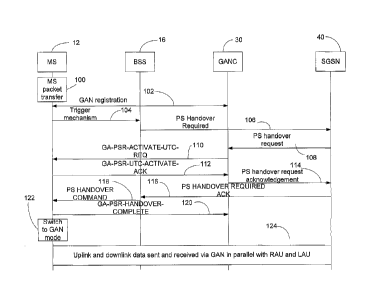
FIG. 2 is a signaling diagram illustrating a PS handover procedure from
a GERAN cell to a GAN cell according to the teachings of the present
invention. First, the MS transfers packets at 100 in a GERAN cell 18. Next,
GAN registration signaling 102 occurs betweens the GANC 30 and the MS 12.
The MS 12 then provides a triggering mechanism to the BSS 16 in 104. The
trigger mechanism may be any trigger which informs the BSS 16 that the MS
12 is ready for a handover to a GAN cell 28 as discussed above. Next, in 106,
the BSS 16 initiates the PS handover preparation phase by communicating with
the SGSN 40. In 108, the SGSN 40 sends a PS handover request to the
GANC 30 in accordance with the typical legacy PS handover preparation
process for the intra-RAT case (GERAN to GERAN) or the inter-RAT case
(UTRAN to GERAN). One exception to typical legacy procedures is that the
GANC 30 performs a Generic Access-Packet-switched Resources (GA-PSR)
Transport Channel (GA-PSR TC) activation during the PS handover
preparation phase (i.e., while the MS is still in GERAN/UTRAN-mode). The
GANC 30 sends the MS a GA-PSR-ACTIVATE-UTC-REQ message 110. In
turn, the MS sends a GA-PSR-ACTIVATE-UTC-ACK message 112 to the
GANC during the preparation phase to confirm allocation of the GA-PSR
Transport Channel. The GANC 30 then sends a PS handover request
acknowledgement 114 to the SGSN 40.
The SGSN 40 then sends a PS handover required acknowledgement
message 116 to the BSS 16. The PS handover is then executed by the BSS
16 sending a PS handover command message 118 to the MS 12. The MS
then sends a GA-PSR-HANDOVER-COMPLETE message 120 to the GANC
and then switches to GAN mode in 122 In 124, uplink and downlink data is
sent and received via the GAN cell 28 in parallel with RAU and LAU. It should
be understood that the same signaling diagram may be utilized for a PS
30 handover procedure from a UTRAN cell to a GAN cell.
FIGs. 3A and 3B are flow charts illustrating the steps of a PS HO
procedure from the GERAN or UTRAN cell according to the teachings of the
present invention. With reference to FIGs. 1-3, the method will now be
CA 02653179 2008-11-21
WO 2007/145583 PCT/SE2007/050409
- 14 -
explained. The method may be utilized for either a GERAN cell or a UTRAN
cell. The method begins in step 200 where the MS 12 transfers packets in the
GERAN cell 18 or the UTRAN cell 22. Next, in step 202, it is determined if the
MS detects that it is within coverage of the CAN cell 28. If it is determined
that
the MS is not within the coverage area of the CAN cell, the method moves to
step 200 where the MS 12 continues to transfer packets in the GERAN/UTRAN
cell.
However, if it is determined that the MS is within the coverage area of
the CAN cell 28, the method moves from step 202 to step 204 where a CAN
registration procedure is conducted between the GANC 30 and the MS 12. In
step 206, the MS sends a PS handover triggering mechanism to the BSS 16 or
RNS 24. The triggering mechanism may be any mechanism to indicate that the
MS supports and requests PS handover to a CAN cell. The triggering
mechanism may be the transmission of measurements for the ARFCN
corresponding to the CAN cell and reporting an RXLEV of 63. By sending
measurements which include the ARFCN corresponding to the CAN cell
combined with the BSS/RNS ability to detect the nature of the reported cell as
described above, the MS is implicitly indicating that the MS supports PS
handover to a CAN cell. An alternative trigger mechanism to sending
measurements (to trigger BSS/RNS recognition of MS support for PS
handover) is to send a new PACCH message/RRC message from the MS to
the BSS 16/RNS 24. Upon receipt of the trigger by the BSS 16/RNS 24, the
BSC/RNS initiates the PS handover preparation phase in step 208. The
preparation ph ase is similar to the legacy PS handover preparation phase.
One exception is that the GANC 30 performs a Generic Access-Packet-
switched Resources (GA-PSR) Transport Channel (GA-PSR TC) activation
during PS handover preparation phase (i.e., while the MS is still in
GERAN/UTRAN-mode). The GANC 30 sends the MS 12 a GA-PSR-
ACTIVATE-UTC-REQ message 110. In turn, the MS 12 sends a GA-PSR-
ACTIVATE-UTC-ACK message 112 to the GANC during the preparation phase
to confirm allocation of the GA-PSR Transport Channel. The GANC 30 then
sends a PS handover request acknowledgement 114 to the SGSN 40. The
SGSN then sends a PS handover required acknowledgement message 116 to
CA 02653179 2008-11-21
WO 2007/145583 PCT/SE2007/050409
- 15 -
the BSC (a Relocation Command would be sent from the SGSN to the RNC for
the case of UTRAN to CAN PS Handover).
The method then moves to step 210 where the PS handover is then
executed by the BSC/RNC sending a PS handover command message 118 to
the MS 12. In step 212, the MS 12 sends a GA-PSR-HANDOVER-COMPLETE
message 122 to the GANC and then switches to the CAN mode. In step 214,
uplink and downlink data is sent and received via the CAN cell 28 in parallel
with RAU and LAU.
PS handover from a CAN cell to a GERAN/UTRAN cell is similar to the
preparation and execution phase as for legacy intra-RAT PS handover
(GERAN to GERAN) or legacy inter-RAT PS handover (GERAN to UTRAN).
However, there are some differences. During CAN registration, the MS 12
sends the GANC 30 a GA-RC Register Request message that includes the
CAN Classmark IE which may be modified to indicate an MS is capable of PS
handover from a CAN cell to a GERAN/UTRAN cell. In an alternate
embodiment of the present invention, a specific type of CAN measurement
information is defined for the PS handover procedure (i.e., compared to the
GA-CSR HANDOVER INFORMATION message for CS handover). The GANC
30 may then detect that an MS 12 supports CAN PS handover if the MS 12
sends these new messages to the CANC.
In addition, at any point when a GA-PSR transport channel is active, the
GANC 30 may determine that the MS is better served in a GERAN/UTRAN cell
and therefore trigger the PS handover procedure if the MS 12 supports PS
handover. The GANC may determine this trigger based on measurement
information sent by the MS 12 to the GANC 30 while in the GA-PSR ACTIVE
state in CAN mode. For example, the GANC 30 may send the MS 12 an
explicit GA-PSR signaling message that indicates when the MS should start
sending measurement reports providing information about GERAN/UTRAN
cells. Alternatively, the MS 12 may perform local measurements and based on
these send the measurement reports providing information about
GERAN/UTRAN cells to the GANC 30.
A GA-PSR Handover Command message may be sent to the MS in the
CAN cell during the execution phase and may then clearly distinguish between
CA 02653179 2008-11-21
WO 2007/145583 PCT/SE2007/050409
- 1 6 -
the cases of PS handover to GERAN cell and a UTRAN cell since the MS
requires a unique way to determine which type of tunneled PS handover
command is present in the GA-PSR Handover Command message.
In the case when a PS handover is conducted from a CAN cell to a
GERAN cell, the MS may be provided with target cell system information during
the PS handover execution phase (e.g., as part of the GA-PSR Handover
Command). The GANC may be able to acquire this system information using
either Radio Information Management (RIM)/Network Assisted Cell Change
(NACC) procedures or using the target BSS to source BSS transparent
container sent by the target BSS during the PS handover preparation phase.
FIGs. 4A and 4B are flow charts illustrating the steps of supporting a PS
handover from a CAN cell 28 to either a GERAN cell 18 or an UTRAN cell 22
according to the teachings of the present invention. With reference to FIGs. 1
and 4, the method of the present invention will now be explained. The method
begins in step 300 where the MS 12 transfers packets in a CAN cell 28. Next,
in step 302, it is determined that the quality of the current CAN cell is
deteriorating and that the MS detects that the MS 12 is within the coverage
area of either the GERAN cell or the UTRAN cell (or both). If it is determined
that the MS 12 is not within the coverage area of the GERAN/UTRAN cell, the
method moves to step 300 where the MS 12 continues to transfer packets in
the CAN cell 28 as long as possible.
However, if it is determined that the MS 12 is within the coverage area of
either the GERAN cell or the UTRAN cell and that the quality of the current
CAN cell is deteriorating, the method moves from step 302 to step 306, where
the MS 12 sends a triggering mechanism to the GANC 30. The triggering
mechanism may be any mechanism to indicate that the MS 12 supports PS
handover to a GERAN/UTRAN cell. Upon receipt of the trigger by the GANC
30, the GANC initiates the PS handover preparation phase in step 308. The
method then moves to step 310 where the PS handover is then executed by
the GANC 30 sending a CAN PS Handover Command message to the MS 12.
The MS 12 is preferably provided with target cell system information during
the
PS handover execution phase (i.e. at least for PS handover from a CAN cell to
a GERAN cell). In step 312, the MS 12 switches to GERAN/UTRAN mode. In
CA 02653179 2008-11-21
WO 2007/145583 PCT/SE2007/050409
- 17 -
step 314, uplink and downlink data is sent and received via the
GERAN/UTRAN cell in parallel with RAU and LAU.
It should be understood, although the present invention describes
support of PS handover between CAN cells and GERAN and UTRAN cells, the
present invention may also be utilized with other types of telecommunication
systems which encompass other types of radio access networks, such as
Advanced Mobile Phone Service (AMPS) system, the Narrowband AMPS
system (NAMPS), the Total Access Communication System (TACS), the
Personal Digital Cellular (PDC) system, the United States Digital Cellular
(USDC) system, code division multiple access (CDMA) system or the E-
UTRAN system (also know as a Long Term Evolution system or simply an LTE
system).
Although preferred embodiments of the present invention have been
illustrated in the accompanying drawings and described in the foregoing
Detailed Description, it is understood that the invention is not limited to
the
embodiments disclosed, but is capable of numerous rearrangements,
modifications, and substitutions without departing from the scope of the
invention. The specification contemplates all modifications that fall within
the
scope of the invention defined by the following claims.