Note: Descriptions are shown in the official language in which they were submitted.
CA 02653181 2008-11-24
WO 2007/144073 PCT/EP2007/004830
1
SOLE FOR SHOES OF THE WATERPROOF AND VAPOR-
PERMEABLE TYPE, AND SHOE PROVIDED WITH SAID SOLE
Technical Field
The present invention relates to a sole for shoes of the waterproof and
vapor-permeable type.
The present invention also relates to a shoe provided with said sole.
Background Art
As is known, most of the perspiration of the foot originates at the
interface between the sole of the foot and the sole of the shoe, and the
perspiration that forms there, being unable to evaporate, condenses on the
plantar insert on which the foot rests; only a minimal part of the
perspiration
evaporates through the upper.
This phenomenon is particularly conspicuous in shoes which have a
rubber sole; in these cases, vapor permeation through the sole is prevented
completely.
In order to solve this problem, shoes with soles which are waterproof
and vapor-permeable (permeable to water vapor) and are made of plastic
material have now been devised for several years.
Their purpose is to allow the escape of the water vapor produced by
the foot with perspiration.
One of the solutions is disclosed for example in US Patent 5044096
and EP 382904 and consists in dividing the rubber sole into two layers
provided with through holes (the tread is associated with the lower layer)
and in interposing a membrane which is waterproof and vapor-permeable
and is connected perimetrically and hermetically to the two layers so as to
not allow water infiltrations.
It is convenient to arrange below the membrane a layer for protecting
it (for example a felt layer), as disclosed for example in US Patent 5983524
and EP 858270.
The need to prevent foreign objects of a certain size from being able
CA 02653181 2013-09-19
2
to arrange themselves inside the holes, with the possibility of damaging both
the felt and the membrane, forces the use of holes having a size of 1_5-2.0
rnm, which are spaced enough to avoid compromising the structural strength
of the tread, thus reducing the vapor permeation area.
One optimum solution meant to increase the vapor permeation area of
the tread is disclosed for example in U.S. Patent Application Publication No.
US20060162183 and in European Patent Application Publication No. EP1545253.
The type of sole disclosed in this last patent application is particularly
adapted to dissipate the large amounts of water vapor that form, with
perspiration, inside the shoes of individuals who have higher-than-average
perspiration.
Excessive foot perspiration can also occur in the case of extremely
hot and humid climates and if shoes are used for sports activities.
The cited patent application discloses a sole which has a structure
comprising a supporting layer which, at least in a preset large portion, is
provided by means of a net (made of synthetic or metallic material).
A membrane made of a material which is impermeable to water and
permeable to water vapor is associated in an upward region with the
supporting layer at least in the provided large net portion, which it covers.
A plastic tread with at least one large through hole at the provided
large portion is joined hermetically to the membrane and to the supporting
layer at least at the perimeter of the large net portion; typically, the tread
is
overrnolded on the net.
This solution, as mentioned, allows to utilize at best the
characteristics of the waterproof and vapor-permeable membrane, but in
certain applications a sole which has a large net may be too rigid or may
have a limited capacity to absorb impacts with the ground.
Disclosure of the Invention
The aim of the present invention is to provide a sole for shoes of the
waterproof and vapor-permeable type which solves the problems described
CA 02653181 2013-09-19
3
in known types.
Within this aim, an important object of the present invention is to
provide a sole for shoes of the waterproof and vapor-permeable type which
allows to increase the vapor permeation area at the tread without reducing
the characteristics of resistance to piercing of the protective means arranged
below the membrane and without compromising characteristics of flexibility
and shock-absorption of the sole.
Another object of the present invention is to provide a shoe which
maximizes vapor permeation without compromising the comfort related to
its flexibility and softness.
According to an aspect of the present invention, there is provided a sole
for shoes, of the waterproof and vapor- permeable type, comprising:
a lower element made of plastic material, on which a tread provided with
a plurality of through holes is formed;
a membrane which is impermeable to water and permeable to water
vapor and is arranged above said lower element so as to be superimposed on
said through holes, said membrane being joined perimetrically and hermetically
to at least one component of the sole so as to avoid the rise of liquids
through
said sole,
vapor-permeable or perforated means for protecting said membrane,
which are arranged below said membrane so as to be superimposed on the area
of said holes, wherein said means for protecting said membrane comprise
individual vapor-permeable or perforated protective elements, each arranged so
as to block a corresponding said through hole, said lower element forming, for
each of said through holes, an undercut region for preventing downward
extraction for each of said protective elements, wherein said membrane
overlaps
said through holes and is joined perimetrically and hermetically to the lower
element to form a single perimetric seal.
According to another aspect of the present invention, there is provided a
shoe comprising a sole as described herein.
Brief description of the drawings
Further characteristics and advantages of the invention will become
CA 02653181 2008-11-24
WO 2007/144073 PCT/EP2007/004830
4
better apparent from the description of some preferred but not exclusive
embodiments thereof, illustrated by way of non-limiting example in the
accompanying drawings, wherein:
Figure 1 is a perspective bottom view of a shoe with a sole according
to the invention;
Figure 2 is a schematic transverse sectional view of a first
embodiment of a sole according to the invention;
Figure 3 is a schematic sectional view of a portion of a mold for
forming a sole according to the invention, illustrating a portion of said
sole;
Figure 4 is a schematic transverse sectional view of a variation of the
first embodiment of the sole of Figure 1;
Figure 5 is a top view of an element for protecting the membrane
provided in a sole according to the invention;
Figure 6 is a schematic sectional view of a portion of a mold for
forming the protective element of Figure 5;
Figure 7 is a schematic sectional view of portion of a mold for
forming a sole according to the invention, which uses the protective element
of Figures 5 and 6;
Figure 8 is a schematic transverse sectional view of a second
embodiment of the sole according to the invention;
Figure 9 is a schematic transverse sectional view of a portion of a sole
which is a variation with respect to the one of Figure 8;
Figure 10 is a schematic transverse sectional view of portion of a sole
which is a variation with respect to the one of Figures 8 and 9;
Figure 11 is a schematic transverse sectional view of a portion of a
sole which is a variation with respect to the one of Figures 8, 9 and 10;
Figure 12 is a schematic transverse sectional view of a sole which is a
variation with respect to the one of Figures 8, 9 and 11;
Figure 13 is a schematic transverse sectional view of a sole which is a
variation with respect to the one of Figures 8, 9, 11 and 12.
CA 02653181 2008-11-24
WO 2007/144073 PCT/EP2007/004830
In the exemplary embodiments that follow, individual characteristics,
given in relation to specific examples, may actually be interchanged with
other different characteristics that exist in other exemplary embodiments.
Moreover, it is noted that anything found to be already known during
5 the patenting process is understood not to be claimed and to be the
subject
of a disclaimer.
Ways to carrying out the Invention
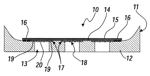
With reference to Figures 1 and 2, a first embodiment of a sole
according to the invention is generally designated by the reference numeral
10, while a shoe which uses the sole 10 is generally designated by the
reference letter C.
The sole 10 comprises a lower element 11, which is made of plastic
material and on which a tread 12 is formed which has a plurality of through
holes 13 provided preferably in the region of the sole related to the
forefoot.
The through holes 13 are much larger than the small ventilation holes
provided on similar soles of the background art and therefore are generally
much larger than 2 mm (for example from 5 to 20 mm).
Above the lower element 11, in practice so as to overlap the through
holes 13, there is a membrane 14 which is impermeable to water and
permeable to water vapor, of a per se known type (such as for example a
membrane known by the trade name Gore-Tex ).
According to a known configuration, a mesh 15 made of synthetic
material is laminated over the membrane 14.
The membrane 14 is perimetrically joined hermetically in a known
manner to at least one component of the sole 10 so as to avoid the rise of
liquids through the sole.
This seal, generally designated by the reference numeral 16, is
provided for example by gluing the lower perimetric portion of the
membrane 14 to the lower element 11 (in practice so as to form a seal from
"below" the membrane).
CA 02653181 2008-11-24
WO 2007/144073 PCT/EP2007/004830
6
The sole also comprises means 17 for protecting the membrane 14
which are vapor-permeable or perforated and are arranged below the
membrane 14, in practice so as to overlap the area of the through holes 13.
Advantageously, the means 17 for protecting the membrane 14
comprise individual vapor-permeable or perforated protective elements 18,
each arranged so as to obstruct a corresponding through hole 13.
In particular, the lower element 11 forms, for each through hole 13,
an undercut region 19 for preventing downward extraction for each
protective element 18.
In this first embodiment, which is clearly visible in the diagram of
Figure 2, the protective elements 18 are flat and are constituted by net
elements 20, made for example of metallic or plastic material, which have a
larger area than the through holes 13.
The net elements 20 are rigidly coupled to the lower element 11, in
this embodiment, by virtue of the overmolding of said lower element 11 on
the edges of said net elements 20 arranged in the mold as inserts.
The portions of the lower element 11 that are superimposed on the
perimetric edges of the net elements 20 in practice constitute said undercut
regions 19 for preventing downward extraction for said net elements 20
(which, as mentioned, constitute the protective elements 18 for the
membrane 14).
Figure 3 is a diagram of a portion of a closed mold 21, which shows
internally a portion of a sole related to a net element 20 (the membrane with
the mesh will be associated subsequently with said sole).
For precise placement of the net element 20, it is possible to use small
pins 22 of the mold 21 onto which each net element 20 is engaged.
A variation to this first embodiment, generally designated by the
reference numeral 100 and shown in Figure 4, provides protective elements,
now designated by the reference numeral 118, which are constituted by
rings 123 made of plastic material which are closed at the center by net
CA 02653181 2008-11-24
WO 2007/144073 PCT/EP2007/004830
7
elements 120, as clearly shown in the plan diagram of Figure 5.
The method of production of said protective elements 118 may entail
overmolding the plastic rings 123 on the peripheral region of the net
elements 120 (as shown in the diagram of the mold 121 of Figure 6) and
subsequently, as shown in Figure 4, gluing said protective elements 118 in
annular recesses 124 provided on the upper face of the lower element 111
and at the upper end of each through hole 113; said annular recesses 124
constitute said undercut regions 119 for preventing downward extraction for
the protective elements 118.
Moreover, said protective elements 118 can be used as mold inserts
onto which the rest of the sole is to be overmolded, as shown in the diagram
of the mold 121a of Figure 7.
It is evident that instead of net elements it is possible to use
equivalently other vapor-permeable or fine perforated elements made of a
material suitable for the requirements, such as for example microstretched
metal sheets, fused and partially compressed synthetic fibers, compressed
natural fibers (for example hemp or coconut fibers), leather and other
materials.
A second embodiment of a shoe according to the invention,
designated by the reference numeral 200 in Figure 8, uses as protective
elements, now designated by the reference numeral 218, vapor-permeable
plugs 220a, whose contour has a cylindrical symmetry or is substantially
shaped like a parallelepiped.
Said vapor-permeable plugs 220a are preferably porous plugs of the
open-cell type or of the type with sintered microspheres, provided for
example by means of sintered granular powders (for example stainless steel,
bronze and other metals or alloys), aluminum foams, porous and vapor-
permeable plastic materials, ceramic materials et cetera, and in general
materials which do not have oxidation phenomena upon contact with water
which might compromise their vapor permeability.
CA 02653181 2008-11-24
WO 2007/144073 PCT/EP2007/004830
8
A wider step-like portion 226a protrudes laterally at the upper end of
said plug 220a and is adapted to be arranged in annular recesses 224
provided on the upper face of the lower element 211 at the upper end of
each through hole 213; said annular recesses 224 constitute said undercut
regions 219a for preventing downward extraction for the protective
elements 218.
Instead of the step-like variation of the wider portion 226a, it is
possible for example to use a vapor-permeable plug 220b, in which the
wider portion 226b tapers downwardly (see Figure 9).
Said vapor-permeable plugs 220a and 220b may be associated with
the lower element 211 both by adhesive bonding and by overmolding.
Figure 10 shows a plug 220c which has, in an intermediate lateral
position of its axial extension, a recess 227 inside which part of the lower
element 211 penetrates so as to provide an undercut region 219c for
preventing downward extraction.
Figure 11 shows a plug 220d, which has, in an intermediate lateral
position of its axial extension, a protrusion 228 which is adapted to
penetrate in the matrix of the lower element 211; the part of the lower
element 211 that lies below said protrusion 228 constitutes an undercut
region 219d for preventing downward extraction.
Said vapor-permeable plugs 220c and 220d are associated with the
lower element 211 preferably by overmolding.
Figure 12 shows another variation of a vapor-permeable plug,
designated by the reference numeral 220e.
Said vapor-permeable plug 220e is of the porous type and has a
completely cylindrical or completely parallelepipedal shape, in practice with
substantially vertical side walls.
In this case, the association with the lower element 211 of the vapor-
permeable plug 220e occurs by overmolding, so that the plastic material of
the lower element 211 penetrates laterally part of said plug 220e due to the
CA 02653181 2008-11-24
WO 2007/144073 PCT/EP2007/004830
9
porosity of the surface of said plug.
The portion of the lower element 211 that penetrates the vapor-
permeable plug 220e constitutes an undercut region 219e for preventing
downward extraction for said plug (shown in the figure by an overlap of the
dashed lines of the lower element 211).
Figure 8 also illustrates a protective layer 229a of the membrane 214
which is additional with respect to the vapor-permeable plugs 220a.
Said protective layer 229a, which is made for example of a vapor-
permeable, water-repellent material which is capable of drying rapidly (for
example a woven fabric, a non-woven fabric or pile cloth) mainly has the
purpose of protecting the membrane 214 against the abrasion of said
protective elements 218 (in this case the plugs 220a); said protective layer
229a is for example laminated to the membrane 214.
In this embodiment, said protective layer 229a has a smaller area than
the membrane 214 (but in any case an area which is larger than, or equal to,
the total area occupied by the through holes 213), so as to leave free the
perimetric edges of said membrane in order to provide the seal 216a from
"below" of said membrane 214 with the lower element 211.
Figure 12 shows the case in which the protective layer of the
membrane 214, now designated by the reference numeral 219e, has the same
area as the membrane.
In this case, the seal of the membrane 214 is performed from "above",
for example by overmolding a mid-sole 230 which surrounds laterally the
membrane and is superimposed on the upper perimetric edges thereof and of
the corresponding mesh 215; above the mesh 215 there is a vapor-permeable
or perforated filler 231.
Figure 13 shows a sole 300, which is constituted by a prepared pack
332 which comprises, from the bottom upwardly, part of the element 311,
the protective layer 329, the membrane 314 and the mesh 315; the tread 312
is integrated on said part of the element 311 and is provided with through
CA 02653181 2008-11-24
WO 2007/144073 PCT/EP2007/004830
holes 313, with which vapor-permeable plugs 320 are associated.
The lower element 311, which constitutes the supporting structure of
the sole, is provided perimetrically with respect to said prepared pack 332.
Said prepared pack 332 is provided separately and then inserted in the
5 mold as an insert onto which the lower element 311 is overmolded; in this
construction, the lower element 311 seals the membrane from "above".
In practice it has been found that the invention thus described solves
the problems noted in known types of vapor-permeable and waterproof
soles; in particular, the present invention provides a sole for shoes of the
10 waterproof and vapor-permeable type which allows optimum vapor
permeability without compromising the characteristics of protection of the
membrane and without compromising the flexibility and shock-absorption
characteristics of the sole.
This has been achieved by providing through holes in the tread which
are larger than the small holes provided in known types of soles and by
associating with each hole vapor-permeable elements for protecting the
membrane.
Through holes of such size do not allow the accumulation of dirt and
therefore maintain their effective shoe ventilation area.
The association of a protective element with each through hole allows
to avoid stiffening, in applications where high flexibility is required, the
entire sole with a vapor-permeable or perforated structure such as a metallic
net associated with a large ventilation hole.
It is evident that it is fundamental for the protective elements of the
membrane to be fixed stably to the lower element with which the tread is
integrated.
From this standpoint, the provision of an undercut region for
preventing downward extraction for each protective element, formed on the
lower element of the sole, ensures this stability.
The invention thus conceived is susceptible of numerous
CA 02653181 2013-09-19
11
modifications and variations, all of which are within the scope of the
appended claims; all the details may further be replaced with other
technically equivalent elements.
In practice, the materials used, so long as they are compatible with the
specific use, as well as the dimensions, may be any according to
requirements and to the state of the art.
Where technical features mentioned in any claim are followed by
reference signs, those reference signs have been included for the sole
purpose of increasing the intelligibility of the claims and accordingly, such
io reference signs do not have any limiting effect on the
interpretation of each
element identified by way of example by such reference signs.