Note: Descriptions are shown in the official language in which they were submitted.
CA 02653325 2014-04-30
64267-1564
OVEN RACK HAVING AN INTEGRAL LUBRICIOUS,
DRY PORCELAIN SURFACE
CROSS-REFERENCE TO RELATED APPLICATION
10001] This application is a continuation-in-part of application serial No.
11/440,992 filed
May 25, 2006.
[0002]
[00031
FIELD OF THE DISCLOSURE..
[0004] The present disclosure is directed to glass, ceramic or porcelain
coated metal
products wherein the porcelain coating has a lubricious surface such that
'repeated sliding
contact against another porcelain surface achieves measureable improvement in
the form of
reduced marring, chipping or flaking of the porcelain of either porcelain
surface. In the
preferred embodiment, these products are porcelain-enameled steel oven racks
that are =
subjected to temperatures above 500 F, usually above 900 F, as in self-
cleaning, pyrolytic
ovens, and the metal is steel wire that has the composition disclosed in this
assignee's U.S.
Patent Nos. 6,837,235 and 6,915,552. Alternately, the
product can be formed of cast iron, such as a burner grate. The preferred
combination of the
steel wire together with the lubricious porcelain coating provides oven racks
which do not
discolor during cooking or during self-cleaning cycles when the oven racks
remain in the
oven, and the porcelain coating does not spall, fish-scale or chip, as a
result of hydrogen out-
gassing, which might othenvise occur from steel at the high temperatures of
self-cleaning
cycles. Further, the porcelain surface of the oven rack has improved wear
performance when
measuring the result of regular sliding contact of the porcelain oven rack
surface against
either an oven wall porcelain rib liner surface or a pcircelain coated so-
called ladder rack
during movement of the oven racks into and out of the oven, surprisingly even
when the oven
rack supports a heavy cooking load, at high cooking temperatures of 350-600 F,
or during
shipping of the oven and rack to the point-of-sale or to the ultimate
consumer.
- 1 -
CA 02653325 2008-11-24
WO 2008/013596
PCT/US2007/012398
BACKGROUND AND PRIOR ART
[0005] As described in this assignee's U.S. Patent Nos. 6,837,235 ('235) and
6,915,522
('522), when a glass-coated steel wire oven rack is subjected to temperatures
above 900 F,
there is an emission of hydrogen gas from the steel upon cooling from that
temperature, and
absent a preventive expedient, the emitted hydrogen gas will attempt to escape
from the steel
through the glass coating causing the glass coating to chip, spall or crack.
[0006] There is no solution to preventing the chipping, spalling or cracking
of glass-coated
steel wire oven racks or of glass-coated drawn steel rod articles, with the
exception of the
solution described in this assignee's '235 and '522 patents and pending
application Serial No.
11/040,641, filed January 21, 2005.
[0007] As described in this assignee's '235 and '522 patents, the drawn steel
rod is subjected
to at least 20% reduction in diameter during cold drawing; and the rod, at the
time it
undergoes drawing, is composed of steel comprising up to about 0.08% carbon
and about
0.001 to about 0.2% of a carbon stabilizing transition metal selected from
vanadium (V),
titanium (Ti), niobium (Nb) and tantalum (Ta). This combination of features
enables the.
glass-coated drawn steel rod article or wire oven rack to overcome the glass
chipping or
cracking problem as a result of hydrogen out-gassing.
[0008] In addition to the hydrogen out-gassing problem experienced at high
temperatures
with porcelain-encapsulated steel oven racks, another very significant problem
has more
recently been discovered during the manufacture, testing and use of the
porcelain-coated
oven racks. It has been found that the porcelain can deteriorate by marring,
flaking or
chipping off of the porcelain material from the oven racks as a result of the
normal periodic
sliding contact between the oven rack porcelain surface and a contacting
porcelain wall
surface of the oven cavity. That is, over the 13 to 15 year normal life
expectancy of an oven,
the repeated sliding porcelain-to-porcelain contact upon insertion and removal
of the
porcelain-coated oven racks, particularly when the oven racks are supporting a
relatively
heavy cooking load, can cause unwanted abrasion, chipping and squeaking of the
sliding
porcelain surface (of one type) against and across a porcelain surface (of the
same or another
type) on the oven wall. The identification of a suitable porcelain composition
that solves this
problem was found to be a daunting task since the porcelain composition must
be strong
enough to solve the chipping, spalling and fish-scaling problems that may
result from the
hydrogen out-gassing of the carbon steel as well as resist damage resulting
from continued
- 2 -
CA 02653325 2014-04-30
64267-1564
heating and cooling cycles experienced in cooking, and especially the high
temperatures of
self-cleaning oven cycles, while maintaining sufficient lubricity and hardness
to pass
enumerable quality tests typically required for a porcelain material to be
suitable as an oven
rack. For example, a suitable porcelain material for an oven rack must pass a
lubrication test;
gloss test; adherence test; thickness test; fish-scale test; must be resistant
to acids; resistant to
alkaline materials; be resistant to crazing; be resistant to abrasion; pass a
rubbing test;
blurring test; toxicity test; humidity test; specific gravity and
corrosion4est as well as others.
Porcelain quality tests generally are specified in the Manual of Tests,
Measurements and
Process Controls PEI-1101, an enameling manual well known in the an.
Even other such tests for porcelain quality are set by ASTM standards.
[0009] After-coating the oven rack with a liquid lubricant, such as the prior
art method of
using vegetable oil, requires repeated reapplication of vegetable oil since
the oil dissipates,
e.g., bums off, in both continuous-cleaning and self-cleaning oven cycles and
also somewhat
during other oven usage such as normal cooking cycles. Prior to this
assignee's out-gassing
-solution; as described in the '235 and '522 patents', commercially
satisfactory porcelain-coated
- ovekraCks tcibe used in self-cleaning pyrolytia oVens=were -non-existent so
that assistance in
altemptirig tei solve the porcelain-to-porcelain' alrásion and flaking problem
in porcelain
-
materials that are regularly subjected to temperatures above 900 F was not
forthcoming from
the priorart. ,
SUMMARY OF THE DISCLOSURE
[0010] Described herein is a lubricious porcelain-coated metal oven rack
designed to be
received within an oven cavity. In the preferred embodiment, the coated metal
oven rack
includes a plurality of elongated steel wire members formed of a special steel
composition
and joined together to form an oven rack having an outer surface; wherein the
diameter of the
steel rod material is reduced by at least about 20% when the steel rod
material is drawn to
form the steel wire; the outer surface of the oven rack being coated by a
glass material having
a lubricious, integral, dry outer surface, the glass material preferably being
porcelain. The
amount of carbon in the steel rod material, the amount of carbon stabilizing
transition metal
in the steel rod material and the degree to which the cross-sectional area of
the steel rod
material is reduced, when the steel wire is drawn from the steel rod material,
is selected, i.e.,
balanced, so as to prevent chipping of the glass material away from the outer
surface due to
the release of hydrogen gas from the steel wire members when the steel wire is
either heated
or cooled.
- 3 -
CA 02653325 2008-11-24
WO 2008/013596
PCT/US2007/012398
[0011] In preferred embodiments, the glass material having a lubricious outer
surface,
preferably porcelain, is coated onto the steel wire in two distinct coating
steps, wherein the
lubricious (porcelain-to-porcelain friction-decreasing) additive may be
homogenous
throughout the two porcelain coatings; only in the outer coat (of the two
porcelain coats); or
may be provided only as a surface feature, such as by treating the porcelain
outer surface
using a process step that provides lubricity only to the outer surface of the
porcelain.
[0012] In a preferred embodiment, the coated steel wire products described
herein are oven
racks designed to be received within an oven cavity. The coated steel wire
oven rack includes
a plurality of elongated steel wire members joined together to form an oven
rack having an
outer surface. The plurality of elongated steel wire members are made from a
steel rod
material containing from about 80 to about 99.9% by weight of iron; from up to
about 0.08%
by weight of carbon, e.g., 0.001% about 0.08% carbon, preferably from about
0.002% to
about 0.05%, and more preferably from about 0.005% to less than about 0.05% by
weight
carbon, and most preferably from about 0.005% to about 0.03% by weight carbon;
and from
about 0.001 to about 0.2% by weight of a carbon stabilizing transition metal
selected from the
group consisting olVanadium, Tantalum,.Titanium, Niobiuin, and mixtures
thereof. The
plurality of elongated steel wire members are made from the Steel rod material
by drawing
the steel rod material to form steel wire; wherein the cross-sectional area of
the steel rod
material is reduced by at least about 20% when the steel rod material is cold
drawn to form
the steel wire. The outer surface of the oven rack is coated by a glass
material, preferably
porcelain, having a lubricious outer surface, wherein the amount of carbon in
the steel rod
material, the amount of carbon stabilizing transition metal in the steel rod
material and the
degree to which the cross-sectional area of the steel rod material is reduced
when the steel
wire is drawn from the steel rod material is selected, i.e., balanced, so as
to prevent chipping
of the porcelain away from the outer surface due to the release of hydrogen
gas from the steel
wire material when the steel wire material is either heated or cooled. In a
preferred
embodiment, the porcelain is coated onto the steel in two distinct coating
steps preferably in
two distinct electrostatic coating processes, followed by a single heating
process in which the
temperature is preferably raised to about 1550 F or cured using infrared (IR)
or other glass
fit fusing techniques known in the porcelain coating or porcelain enameling
art. In alternate
embodiments, the heating process may be repeated and in yet other alternate
embodiments, a
wet coating, CVD, physical vapor deposition (PVD) or other processes can be
used for
applying the porcelain coat(s) to the steel wire oven rack.
- 4 -
CA 02653325 2014-04-30
64267-1564
100131 The plurality of elongated steel wire members are made from steel rod
material
containing from about 80 to about 99.9% by weight of iron, up to about 0.08%
by weight
carbon, e.g., from about 0.001 to about 0.08% by weight of carbon, and from
about 0.001 to
about 0.2% by weight of a transition metal that will have a stabilizing effect
on the carbon in
the elongated steel wire members such that the carbon absorbs less hydrogen
gas when the
steel wire member is heated to temperatures above 500 F than it would in the
absence of the
carbon stabilizing transition metal. In preferred embodiments, the transition
metal is selected
from the group consisting of Vanadium, Tantalum, Titanium and Niobium, and in
the most
preferred embodiment, the transition metal is Vanadium. The plurality of
elongated steel wire
members are preferably made from steel rod material by a cold drawing process
to reduce the
diameter of the steel wire. In the preferred process, the steel rod is pulled
through a cold die
that gradually reduces in diameter so that the rod is drawn repeatedly through
the die and the
cross-sectional area of the rod is reduced to form a steel wire having a cross-
sectional area of
diminished diameter. In preferred embodiments, the diameter of the steel wire
is diminished
at least about 20%, preferably at least about 30%, more preferably at least
about 40%, even
more preferably at least about 45%, and most preferably at least abobt 50%. It
will be.
. .
appreciated that the diameter reduction creates voids in the steel wire which
are desirable.to
provide cavities info ivhich hydrogen gas can be received and, perhaps
compressed, without
creating pressure to be released from the surface of the' steel wire once the
steel wire is Coated
with porcelain. It will be appreciated, that the diameter reduction, which
creates cavities in
the steel wire, and the inclusion of carbon stabilizing transition metal
elements so that the
steel absorbs hydrogen, will diminish the degree to which hydrogen gas out-
gassing causes
cracking, spalling and chipping of the porcelain surface of the elongated
steel wire members
of the oven rack which are coated by the glass material.
100141 In other embodiments, the metal structure coated with a lubricious
glass material
may be cast iron; or other identified materials such as Type I, II or III
porcelain enameling
steels, (as described in Manual for Selection of Porcelain Enameling Steels
PEI-201), hereby
incorporated by reference; or any metal that will not cause chipping, flaking,
spatting or fish-
scaling of the glassy coating when subjected to temperatures of a self-
cleaning cycle of an
oven above 500 F, preferably above 900 F.
- 5 -
CA 02653325 2014-04-30
64267-1564
[0014a] Another embodiment relates to a lubricious glass-coated metal
article capable
of withstanding repeated heating and cooling between room temperature and at
least 500T
without chipping or cracking the glass coating, comprising: a metal article;
and a glass coating
disposed on the metal article, wherein: the glass coating includes about 0.1
to about 20% by
weight of a homogeneously distributed dry refractory lubricant material, the
dry refractory
lubricant material consists of particles having a particle size of less than
about 45 JAM and an
aspect ratio of less than 2:1, and, the dry refractory lubricant material is
selected from the
group consisting of carbon; graphite; boron nitride; cubic boron nitride;
molybdenum (FV)
sulfide; molybdenum sulfide; molybdenum (IV) selenide; molybdenum selenide,
tungsten
(IV) sulfide; tungsten disulfide; tungsten sulfide; silicon nitride (Si3N4);
TiN; TiC; TiCN;
Ti02; TiAlN; CrN; SiC; diamond-like carbon; tungsten carbide (WC); zirconium
oxide
(Zr02); zirconium oxide and 0.1 to 40 weight % aluminum oxide; alumina-
zirconia;
antimony; antimony oxide; antimony trioxide; and mixtures thereof
10014b1 Another embodiment relates to the lubricious glass-coated
metal article of
above, wherein the metal article is a steel article, said lubricious glass-
coated article being
capable of withstanding a hydrogen-emitting temperature sufficient to emit
hydrogen gas from
the steel such that hydrogen gas emitted from the steel is contained within
cavities formed in
the steel during drawing, without escaping through the glass coating, such
that the glass
coating does not chip or crack at said hydrogen-emitting temperature, and the
steel article
comprises a steel write member drawn from a steel rod such that the diameter
of the steel rod
is reduced at least 20%, and the steel rod comprises the following components
by weight:
Iron: about 80% to about 99.9%; Carbon: up to about 0.08%; and a transition
metal selected
from Vn, Ta, Ti, Ni or mixture of any two or more: 0.001% to about 0.2%,
wherein the
amount of carbon in the steel rod, the amount of carbon stabilizing transition
metal in the steel
rod and the degree to which the diameter of the cross-sectional area of the
steel rod is reduced,
when the steel wire member is drawn from the steel rod, are selected to
prevent chipping of
the glass material away from the outer surface of the article due to the
release of hydrogen gas
from the steel wire member when the glass-coated steel wire member is heated
to a
temperature above 900 F.
- 5a -
CA 02653325 2014-04-30
64267-1564
10014c] Another embodiment relates to the lubricious glass-coated
metal article of
above, wherein the metal article comprises steel wire oven rack comprising: a
plurality of
elongated steel wire members joined together to form an oven rack having an
outer surface;
the plurality of elongated steel wire members being made from a steel rod
material containing
up to about 0.08% by weight carbon; the plurality of elongated steel wire
members being
made from the steel rod material by drawing the steel rod material to form
steel wire; wherein
the diameter of the cross-sectional area of the steel rod material is reduced
by at least about
20% when the steel rod material is drawn to form the steel wire; wherein the
outer surface of
the oven rack is coated with the glass coating; and wherein the amount of
carbon in the steel
rod material and the degree to which the diameter of the cross-sectional area
of the steel rod
material is reduced, when the steel wire is drawn from the steel rod material,
are selected to
prevent chipping of the glass material away from the outer surface of the
article due to the
release of hydrogen gas from the steel wire members when the glass-coated
steel wire
members are heated to a temperature above 900 F.
[0014d] Another embodiment relates to a method of making a lubricious glass-
coated
metal article comprising a steel wire oven rack, comprising the steps of: a)
providing a steel
rod material containing from about 80 to about 99.9% by weight of iron, up to
about 0.08% by
weight of carbon and from about 0.001 to about 0.2% by weight of carbon
stabilizing
transition metal selected from the group consisting of Vanadium, Tantalum,
Titanium and
Niobium; b) drawing the steel rod material to form steel wire, wherein the
diameter of the
cross-sectional area of the steel rod material is reduced by at least about
20%; c) forming a
plurality of elongated steel wire members from said steel wire; d) joining the
plurality of steel
wire members to one another to form interconnected parts of a steel wire oven
rack; and e)
coating the steel wire oven rack with a lubricious porcelain containing about
1% to about 10%
by weight of a dry refractory lubricant material that consists of particles
having a particle size
less than about 45 jAM and an aspect ratio of less than 2:1; wherein the
amount of carbon in the
steel rod material, the amount of carbon stabilizing transition metal in the
steel rod material
and the degree to which the diameter of the cross-sectional area of the steel
rod material is
reduced, when the steel wire is drawn from the steel rod material, are
selected to prevent
chipping or spalling of the glass material away from the outer surface of the
article due to the
- 5b -
CA 02653325 2014-04-30
64267-1564
release of hydrogen gas from the steel wire members when the glass-coated
steel wire
members are heated to a temperature above 900 F.
10014e1 Another embodiment relates to a method of cleaning the
lubricious glass-
coated steel wire oven rack of above, comprising: heating a oven containing
the lubricious
glass-coated steel wire oven rack to a temperature above 900 F.
100151 Ranges may be expressed herein as from "about" or
"approximately" one
particular value and/or to "about" or "approximately" another particular
value. When such a
range is expressed, another embodiment includes from the one particular value
and/or to the
other
- 5c -
CA 02653325 2008-11-24
WO 2008/013596
PCT/US2007/012398
particular value. Similarly, when values are expressed as approximations, by
use of the
antecedent "about," it will be understood that the particular value forms
another embodiment.
[0016] The above-described features and advantages along with various
advantages and
features of novelty are pointed out with particularity in the claims of the
present disclosure
which are annexed hereto and form a further part hereof. However, for a better
understanding
of the disclosure, its advantages and objects attained by its use, reference
should be made to
the drawings which form a further part hereof and to the accompanying
descriptive matter in
which there is illustrated and described preferred embodiments of the
preferred disclosure.
BRIEF DESCRIPTION OF DRAWINGS
[0017] Referring to the drawings, where like numerals refer to like parts
throughout the
several views:
[0018] Figure 1 is a plan view of a coated oven rack in accord with the
present disclosure;
[0019] Figure 2 is a side view of the oven rack shown in Figure 1;
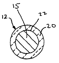
[0020] Figure 3 is a cross-sectional view of an outside framing wire 12 as
seen from the
line 3-3 of Figure 1;
[0021] Figure 4 is a plan view of an alternate oven rack in accord with the
present
disclosure;
[0022] Figure 5 is a side view of the alternate oven rack shown in Figure 4;
[0023] Figure 6 is a cross-sectional view of an outside framing wire 12' as
seen from the
line 6-6 of Figure 4;
[0024] Figure 7 is a plan view of a further alternate oven rack in accord with
the present
disclosure;
[0025] Figure 8 is a side view of the oven rack shown in Figure 7;
[0026] Figure 9 is a cross-sectional view of an outside framing wire 12' as
seen from the
line 9-9 of Figure 7;
[0027] Figure 10 is a broken-away front view of an oven showing a lubricious
porcelain-
coated oven rack positioned within a porcelain-coated oven cavity;
- 6 -
CA 02653325 2008-11-24
WO 2008/013596
PCT/US2007/012398
[0028] Figure 11 is a schematic drawing of the friction and wear testing
apparatus used to
collect the friction and wear data shown in Figures 13A, 13B, 14A and 14B;
[0029] Figure 12 is a bar graph showing the Vickers microindentation hardness
values
collected on a baseline and seven test samples containing different dry
lubricants in the oven
rack porcelain coatings (top coat);
[0030] Figures 13A, 13B, 14A and 14B are bar graphs showing the friction and
wear
behavior at 50N and 1000 cycles (Figs. 13A and 13B) and 13N, 600 cycles (Figs.
14A and
14B) on the baseline and seven test samples; and
[0031] Figure 15 is a graph comparing wear and friction coefficient on the
baseline and test
samples containing TiO2 in relation to TiO2 particle size.
DETAILED DESCRIPTION OF THE PREFERRED EMBODIMENTS
[0032] A lubricious outermost or uppermost surface on the oven rack porcelain
coating can
be achieved either by mixing a dry lubricant refractory powder homogeneously
into the
porcelain composition and then applying the porcelain composition to the steel
oven rack, or
the porcelain coating can be applied to the steel oven rack :and sintered
followed by coating .
the sintered porcelain with a lubricious, temperature-resistive coating
composition. When a
dry lubricant surface layer is applied over a sintered porcelain coating, the
dry lubricant
active material may form a portion of the uppermost coating layer of the
porcelain material,
dispersed homogeneously in additional fine powdered refractory materials or,
the dry
lubricant active material may be discontinuously or continuously embedded into
the surface
of the porcelain coating material as disclosed in U.S. published application
2006/0089270
Al, hereby incorporated by reference.
[0033] In accordance with a preferred embodiment, the lubricious porcelain
material is
coated over the steel oven rack in one or more coating steps, preferably
multiple coating
steps, using an electrostatic dry powder spray. Other suitable coating methods
include wet
spray, electro-static wet spray, wet flow coating, wet dip, electro-phoretic
deposition (EPE-
electro-phoretic enameling), chemical vapor deposition (CVD), physical vapor
depositions
(PVD), plasma deposition, and sputtering. At least this surface coating layer,
as applied on at
least the sidebars (i.e., edge framing wires of the oven rack) that contact
the oven cavity side
wall and/or its protruding rack supports, should include a dry lubricant-
containing
composition in an amount of about 0.1% to about 20% by weight, preferably
about 0.5% to
about 10% by weight, more preferably about 2% to about 5% by weight, and most
preferably
- 7 -
CA 02653325 2008-11-24
WO 2008/013596
PCT/US2007/012398
about 3% by weight. The selected dry lubricant used cannot otherwise
compromise the final
porcelain coating on the oven rack, as such porcelain coating must still pass
the above-
mentioned, required quality control tests for porcelain-coated oven racks.
Suitable dry
lubricant porcelain additives include homogeneously distributed fine powdered
particles, e.g.,
1 nm to about 200 pm, preferably 5 nm to about 200 pm, more preferably 10 nm
to less than
about 105 pm, more preferably 20 nm to less than 45 pm, of carbon; graphite;
boron nitride,
preferably cubic boron nitride; molybdenum (IV) sulfide; molybdenum disulfide;
molybdenum sulfide; molybdenum (IV) selenide; molybdenum selenide, tungsten
(IV)
sulfide, tungsten disulfide, tungsten sulfide, silicon nitride (Si3N4); TiN;
TiC; TiCN; Ti02;
TiA1N; CrN; SiC; diamond-like carbon; tungsten carbide (WC); zirconium oxide
(Zr02);
zirconium oxide or 0.1 to 40 weight % aluminum oxide; alumina-zirconia; and/or
antimony
or its oxides or trioxides. The dry lubricant is conveniently distributed
throughout the
porcelain or glass fit outermost coating composition in one of two ways.
First, it can be
done by adding the dry lubricant to the glass fit (porcelain composition) and
then milling the
entire porcelain composition containing the dry lubricant to the final
particle size distribution,
so that the dry lubricant has approximately the same particle size as the
other glass
components. Second, it can also be done by manuallyadding the dry lubricant to
the
porcelain outermost coating composition. The particle size of the glass frit
or porcelain
compositions described herein is not critical and should be the common
particle size
distribution used by those skilled in the art of porcelain enameling of steel,
e.g., 5 pm to
about 200 pm. The lubricious porcelain composition can be adhered to the metal
oven rack
in any manner known in the art, e.g., electrostatically, preferably by
electrostatic dry powder
spray, as in electro-porcelain enameling. If the porcelain powdered material
is difficult to
adhere, a nickel-based or cobalt-based pretreating composition may be coated
on the steel
prior to the porcelain coating for better adherence of the porcelain to the
metal oven rack, as
well known in the art.
[0034] In another embodiment, the porcelain-coated steel is over-coated (i.e.,
over the base
porcelain coat) with a ceramic wear-resistant powdered refractory composition,
generally in a
thin layer, e.g., 1 to 10 mils, of wear-resistant ceramic material having, for
example, a particle
size in the range of about 5 to about 200 microns, preferably about 10 to
about 45 microns,
followed by sintering, wherein the dry lubricant included in at least a top
layer (outermost
coating) of the ceramic material, has a particle size is in the range of 1 nm
to about 200 pm,
preferably 5 nm to about 200 pm, more preferably 10 nm to less than about 105
pm, more
preferably 20 nm to less than about 45 pm.
- 8 -
CA 02653325 2008-11-24
WO 2008/013596
PCT/US2007/012398
[0035] In one embodiment, the lubricious wear material is a ceramic wear-
resistant powder
such as a carbide, particularly a chrome carbide. The chrome carbide is
typically a material
such as Cr23C6, Cr7C3, Cr3C2, and combinations thereof. The chrome carbide is
generally in
the form of a pre-alloyed carbide powder, wherein the particles of the powder
are
homogeneous and uniform throughout their cross sections. Alternatively, the
chrome
carbide, such as Cr3C2, is blended with another material, such as NiCr which
functions as a
metallic binder. The carbide may be subsequently treated with a halogen
etchant gas at high
temperature to provide additional lubricity in the integral surface thus-
formed, as described in
U.S. 6,579,833, hereby incorporated by reference.
[0036] In another embodiment, the particulate material for the lubricious
coating is
comprised of an alloy wear material. In this case, it is advantageous to
utilize an alloy that
forms a lubricious oxide film over its surface during actual use, which oxide
functions to
lubricate the interface between the treated porcelain surfaces of the oven
racks and the
porcelain surfaces of the oven cavity walls at high temperatures (e.g., at
least about 900 F
during oven cleaning) to reduce wear. For example, wear is reduced due to
presence of the
oxide forming alloy during the self-cleaning oven cycle. One particular group
of materials
that forms a lubricating or lubricious oxide film includes cobalt alloys.
Suitable cobalt-based
lubricious alloys include the following:
(1) 28.5 wt % molybdenum, 17.5 wt % chromium, 3.4 wt % silicon, balance
cobalt;
(2) 22.0 wt % nickel, 22 wt % Cr, 14.5 wt % tungsten, 0.35 wt % silicon,
2.3 wt
% boron, balance cobalt;
(3) 10 wt ')/0 nickel, 20 wt % Cr, 15 wt % tungsten, balance cobalt;
(4) 22 wt A nickel, 22 wt % Cr, 15.5 wt A tungsten, balance cobalt; and
(5) 5 wt % nickel, 28 wt % Cr, 19.5 wt % tungsten, balance cobalt.
[0037] The lubricious, wear resistant outer coating is fused to the underlying
porcelain by
heating to the fusing temperature, e.g., 1550 - 2000 F followed by cooling.
Alternatively, the
lubricious wear-resistant cobalt or chrome carbide material or cobalt-based
alloys can be
applied directly to the metal oven rack and fused thereon to provide the
lubricious, wear-
resistant surface.
[0038] Other useful methods of applying the initial porcelain coating over the
steel oven
rack or for applying a final lubricious coating layer over the base porcelain
layer, include
- 9 -
CA 02653325 2014-04-30
64267-1564
chemical vapor deposition and plasma deposition, as well as sputtering. It
should be noted
that sputtering is a momentum transfer process wherein atoms of the coating
material are
bombarded onto an underlying porcelain layer by energetic particles. The
bombarding
species are generally ions of a heavy inert gas, such as argon. The sputtered
dry lubricant
atoms collide repeatedly with the heavy inert gas atoms before reaching the
porcelain layer
where they condense to form a coating of the lubricious, wear resistant outer
layer. As well
known in the art, the underlying porcelain layer may be given a pretreatment,
e.g., a plasma
treatment to help the outer lubricious, wear-resistant layer adhere to the
outer surface of an
underlying porcelain layer. Plasma ion bombardment of the outer surface of an
underlying
porcelain layer may be useful to modify the outer layer of the porcelain by
plasma etching in
order to achieve better adherence of an outermost layer of lubricious, wear-
resistant
refractory powder material in order to achieve excellent bonding of the final
lubricious
coating layer,
[0039] Another excellent final finishing lubricious surface coating material
includes the
self-lubricating material PS-200 developed by NASA, which is a chromiurri
carbide matrix
having particles of silver and calcium fluoride -barium fluoride eutectic
dispersed therein. In
accordance with this embodiment, the chromium carbide matrix may be. applied
directly over,
an underlying porcelain material or, as described in U.S. Patent No.
5,413,8.77,
the underlying material may be a zirconia thermo barrier material
and the outer chromium carbide layer may be nickel alloy-bonded thereto.
100401 In accordance with still another embodiment of providing an outer
lubricious, wear-
resistant temperature-resistant outer surface on the oven rack and/or interior
surface of the
oven cavity, the glassy or porcelain material can-be formed from a metal
carbide, such as
silicon carbide, and treated in a halogen-containing gaseous etchant at high
temperature, e.g.,
about 100 C to about 4000 C, preferably about 800 C to about 1200 C in order
to form an
integral carbon or diamond surface on the metal carbide, as disclosed in U.S.
Patent No.
6,579,833. Another method for forming a diamond surface
on the outside of the oven rack or exterior of the oven cavity is disclosed in
U.S. Patent No.
5,108,813 and published U.S. Application No. 2006/0059688 Al.
[00411 Referring now to the drawings, and in particular Figures 1-3, a
lubricious, dry
porcelain-coated metal wire oven rack 10 is shown having a lubricious, dry
outer surface
thereon ancUor on the porcelain coating 13 of the oven where the oven rack 10
slides into
- 10-
CA 02653325 2008-11-24
WO 2008/013596
PCT/US2007/012398
position within the oven cavity (see Fig. 10). Preferably, the oven rack 10
has an entire outer
surface that is lubricious, but it is only necessary to provide the lubricious
material in or on an
outside edge framing wire portion 12 or on the oven side walls where the
outside edge
framing wire 12 contacts the oven cavity. The porcelain-coated metal oven wire
rack 10
includes the outside edge framing wire 12 stabilized by two frame stabilizing
support wires
14 and a series of upper surface metal wire members 16 which generally run
front to back to
provide an upper support surface for oven utensils (not shown) that are placed
on the coated
oven rack 10. Preferably the upper support surface also includes the
lubricious porcelain
surface for helping reduce abrasion, chipping, flaking, spalling and other
damage to the
porcelain material during insertion and removal of cooking pans and utensils.
[0042] Referring now also to Figures 4-6, an alternate oven rack 10', as
described herein, is
shown that has only minor differences from the oven rack 10 shown in Figures 1-
3.
[0043] Referring now also to Figures 7-9, a further alternate oven rack 10" in
accordance
with the articles and method described herein is shown, having a few other
minor differences,
but in most other ways being virtually the same as the oven racks shown in
Figures 1-6.
[0044] The preferred oven rack 10 is coated with a lubricious glass material
20, preferably
porcelain, which is coated onto the'outer surface 22 of welded steel wire
parts 15 of the
coated oven rack 10, in a process which generally follows these steps. Steel
rod material (not
shown) is preferably purchased, which is made primarily of iron but includes
the elemental
composition shown below, in Table 1.
-11-
CA 02653325 2008-11-24
WO 2008/013596
PCT/US2007/012398
TABLE 1
PORCELAIN WIRE SUBSTRATE B SPECIFICATIONS
0.259 Diam. 0.192 Diam. 0.239 Diam.
Rod Size 5/16 9/32 5/16
Area Reduction 31% 53% 41.50%
Chemistry Substrate B
111111Mart:, 411C1 0.259 Diam. 0.192 Diam. 0.239 Diam.
Carbon 0.046% 0.052% 0.051%
Vanadium 0.014% 0.012% 0.013%
Manganese 0.350% 0.360% 0.340%
Phosphorus 0.004% 0.003% 0.003%
Sulfur 0.004% 0.004% 0.005%
Silicon 0.130% 0.140% 0.130%
Copper 0.110% 0.100% 0.120%
1" Sample Size Substrate B (pre-fire)
Tensile Testing 0.259 Diam. 0.192 Diam.
0.239 Dawn.
Yield Strength 88200 100300 98600
Ultimate Strength 89700 103400 ,102600
% Elongation in 1" 21 . 15 20
% Reduction of Area 71 67 , 67 .
1" Sample Size Substrate B (post-fire)
Tensile Testing 0.259 Diam. 0.192 Diam.
0.239 Diam.
Yield Strength 57200 41400 51900
Ultimate Strength 71700 58100 70000
% Elongation in 1" 40% 43% 37
% Reduction of Area 77% 80% 79
PEMCO POWDER-lst Coat: GP2025 (CAS# 65997-18-4), 2nd Coat: GP1124 (CAS#
65997-18-4, plus 0.1-20% dry lubricant)
Furnace Line Speed: 22 ft/min (494 hangers/hour), 988 parts/hour
Washer Line Speed: 22 ft/min (494 hangers/hour), 988 parts/hour
4-10 mil thickness
1585 F Zone 1 Temp.
1543 F Zone 2 Temp.
25 minutes in furnace
10,000 lbs/hr maximum line capacity
Specific Gravity: 2.59
[0045] The preferred steel rod is then drawn in an area reduction process,
preferably
through a cold (e.g., room temperature) die, to reduce the diameter of the
cross-sectional area,
- 12 -
CA 02653325 2008-11-24
WO 2008/013596
PCT/US2007/012398
preferably at least about 20%, more preferably at least about 30%, more
preferably at least
about 35%, even more preferably about 40%, even more preferably about 45%, and
most
preferably about 50%, in order to incorporate cavities within the steel wire
which allow steel
wire-released hydrogen to be received within the cavities and also to reduce
the diameter of
the wire to that which is desired. The table above gives the general
specifications for non-iron
elements and other aspects of the steel wire and the steel rod used to make
the steel wire.
[00461 Once the preferred steel rod is converted into wire in the wire drawing
process, the
steel wire is straight cut to predetermined lengths according to need. The
various cut steel
wire members are then formed, e.g., bent, as needed to provide the various
parts of the coated
oven rack. These parts are then welded together to form an oven rack substrate
(not shown),
for subsequent coating, in a standard welding operation. The oven racks are
then cleaned in a
washing process and then power acid washed with an electrically charged acid
wash material
to remove any remaining weld scale. The rack is then dried in an oven at about
500 F and
then air cooled. The clean oven rack is then sprayed with powdered glass
preferably in an
electrostatic charged paint (porcelain enameling) process in which the oven
rack substrate is-
charged negatively and the glass powder is charged positively. Other metal
rack-cleaning,
methods may be Used e.gõ blasting (glass beads, steel balls or sand)
ultrasonic cleaning, high,
temperature or low temperature alkaline cleaning or acid cleaning; or the
like.
100471 The preferred spraying process (electrostatic dry powder spray) is
divided into a first
coating process in which a first or base coat is placed upon the oven rack
substrate. In
preferred embodiments the first coat is a Pemco powder, GP2025 (CAS# 65997-18-
4) from
Pemco International Corp. It will be appreciated that other similar or
equivalent porcelain
powders may also be used in alternate embodiments. After the first coat is
applied a second
or top coat is applied using the same process. In preferred embodiments, this
top coat is a
Pemco powder, GP1124, from PEMCO (CAS# 65997-18-4) containing 0.1% to about
20%,
preferably 0.5% to about 10% of a dry lubricant refractory material having a
particle size less
than about 200 pm, preferably less than about 105 pm, more preferably less
than about 45 pm,
as previously described. If desired for aesthetic reasons, the final coating
may also include a
coloring refractory material, such as Ti02, generally of a much larger
particle size, e.g., >200
pm, added to the milled porcelain composition and homogeneously distributed,
in an amount
of about 0.1 to 10% by weight, more preferably about 1% to about 5%, to
provide white
surface fleck coloring in the otherwise black composition. Again, it will be
appreciated that
other similar or equivalent powders containing the active dry lubricant
powder, distributed
- 13 -
CA 02653325 2008-11-24
WO 2008/013596
PCT/US2007/012398
homogeneously throughout, may also be used in alternate embodiments. The
coated oven
rack substrate is then heated in an oven to about 1500-1600 F, e.g., about
1550 F for about
25 minutes and then cooled. This coating and baking process is generally
referred to as a
double coat, single fire coating process. The coated oven racks are then
cooled and then
packaged for shipping to the customer. It is to be noted that, in view of the
lubricious outer
coating, and contrary to the prior art, the lubricious outer surface is dry,
and no additional
step of then after-coating the finished porcelain-coated steel wire oven rack
with a suitable
liquid lubricant, such as vegetable oil, e.g., Wesson oil, is needed.
[0048] In an alternate process to provide a lubricious outer coating, the oven
rack substrate
is coated using a wet spray process, wherein the porcelain is coated onto the
steel wire, in
number of steps selected from each of five distinct wet coating processes
including wet spray,
electrostatic wet spray, wet flow coating, wet dip or electro-phoretic
deposition, or, more
specific, as applied to porcelain, "EPE-Electro-phoretic enameling." This
later process
involves the use of a dip system where electric power is used to deposit
porcelain enamel
material on a metal surface. The wet coating processes can be single step,
double step or
multiple step processes followed by at least single or double heating process
steps in which
the temperature is preferably raised to a temperature in the range of about
1500 F to about
1600 F, preferably about 1550 F. In these processes, porcelain can be coated
to steel by any
well known basic methods of wet spraying by air atomization, including hand
spraying,
automatic spraying and electrostatic spraying. When the steel oven rack is
processed through
a dipping operation, the part is immersed in the "slip", removed, and the slip
is allowed to
drain off. In flow coating, the slip is flowed over the part and the excess is
allowed to drain
off. Carefully controlled density of the porcelain enamel slip and proper
positioning of the
part is necessary to produce a uniform coating by dip or flow coat methods.
The dry
lubricant-containing porcelain composition can be coated on the steel oven
racks by
immersion or flow coating, as well, by five basic methods: hand dipping, tong
dipping,
automatic dip machines or systems, electro-phoretic deposition systems and
flow coating. It
will be appreciated that any number of these various methods may be adapted
for use in
providing a final porcelain layer or surface that is sufficiently lubricious
for porcelain-to-
porcelain sliding contact without the need for a subsequently-added liquid or
oil lubricant for
wear-resistance or any periodic re-applications of the same to the oven rack
by the ultimate
consumer.
- 14 -
CA 02653325 2008-11-24
WO 2008/013596
PCT/US2007/012398
[0049] Other potential metal substrates to receive a lubricious porcelain
coating can include
Type I, II, and III porcelain enamel coated steels, as described in PEI-201
Manual for
Selection of Porcelain Enameling Steels. Examples of other porcelain coated
wire, cast iron
or other metal products to receive a lubricious porcelain coating in addition
to porcelain
coated oven racks includes ladder racks, barbeque grill racks and stove burner
grates.
Experimental
[0050] Some of the above-mentioned dry lubricant materials were tested for
their
tribological properties as coatings on the oven racks described herein.
Hardness
[0051] The Vickers microindentation hardness values of the baseline and
modified coating
are shown in Fig. 12. There are two observations:
= Most modified coatings were slightly softer than the baseline except #6
that
turned out to be harder.
= The #1, #3, and #6 coatings had no visible cracking under indentation,
implying their less brittleness compared with the baseline and others (#2, #4,
#5, and #7) that clearly showed indentation-induced Cracks.
Friction and Wear Tests
[0052] Eight racks with seven modified enamel coatings (#1-7) and a baseline
were tested.
Coating specifications are show in Table 2. (The coating thicknesses were
calculated based
on the wear scar measurements described later.)
[0053] The WS2 additive produced non-smooth porous enamel coating (#3),
because the
curing temperature (1150 F) was above the critical oxidation temperature
(1000 F) of WS2.
Table 2. Specifications of Coatings.
Enamel coating BL #1 #2 #3 #4 #5 #6 #7
Additive material N/A TiO2 TiO2 WS2 TiO2 TiO2
TiO2 TiO2
Additive particle N/A -325 mesh 0.9-1.6 - -
100 mesh -140, +325 mesh 30-40 10x40
size (<45 gm) gm (<145 gm) (45-105 gm) nm
11111
Coat. Thick. 173 241 213 337 143 185 173 213
(11m)
[0054] Vickers microindentation was conducted under a 200 g-g load to measure
the
hardness of coatings.
- 15 -
CA 02653325 2008-11-24
WO 2008/013596
PCT/US2007/012398
[0055] Friction and wear tests were conducted on those racks by rubbing
against a baseline
oven liner using cylinder-on-flat reciprocating sliding test configuration, as
schematically
illustrated in Fig. 11, on a Plint TE-77 tribo-tester. Cylinders were cut off
oven rack rims
with a length of 20 mm. Flats were cut off from a baseline oven liner in the
size of 25.4x25.4
mm. Sliding stroke was 10 mm and oscillation frequency was 5 Hz. All coatings
were tested
at 400 F (204 C). Two sets of tests were conducted:
= Test Set I: 50 N load and 1000 cycles. The 50 N load was used to generate
a
nominal initial contact stress of 194 MPa, similar to that for rack-on-liner
in
oven under 40 lbs load (see Figs. 13A and 13B).
= Test Set II: 13 N load and 600 cycles. The 13 N load produced a nominal
initial contact stress of 98 MPa, similar to that for the rack-on-liner in
oven
under 10 lbs load (See Figs. 14A and 14B).
[0056] The results for Test set I are shown in Figs. 13A and 13B.
[0057] The results for Test set II are shown in Figs. 14A and 14B.
[0058] The #1, #2, and #6 racks had about 35% w,ear reduction compared with
the baseline.
Test Set 1(50 N, 1000 cycles)
[0059] It was observed that the friction behavior .of all coatings was in a
similar pattern
during the test: started relatively high followed by a gradual decrease but
then climbed up to
a higher level. The turnaround point was when the rack coating wore through
and the
substrate metal started in contact. Most coatings wore through during the 1000-
cycle test.
The coating survival time depended on both the coating thickness and wear-
resistance. Based
on the wear scar measurement, the calculated coating thickness varied
significantly, from 173
to 337 tim, as listed in Table 2.
[0060] Friction and wear results of the baseline and seven modified enamel
coatings are
show in Figs. 13A and 13B. Initial friction coefficient for all the coatings
was in a narrow
band of 0.7-0.75. The steady-state friction coefficient, captured right before
coating wear-
through, varied in a larger range, 0.51-0.66. The #1 and #6 racks produced
lower friction
than the baseline by 15%.
[0061] The wear volumes of the coatings were calculated by wear scar
measurement.
Results are shown in Fig. 13B. All modified coatings had lower wear rates than
the baseline
to some extent.
- 16 -
CA 02653325 2008-11-24
WO 2008/013596
PCT/US2007/012398
Test Set II (13 N, 600 cycles)
100621 In test set II, the TiO2 modified coatings were benchmarked against
both dry and
oiled baselines. The WS2 modified coating (#3) was ruled out due to its
porosity and
unsatisfactory performance in test set I. With a lower load 13 N applied in
test set II, all
coatings survived without wearing through. Friction and wear results are
summarized in
Figs. 14A and 14B. Some observations are made below:
= The oiled base (baseline) showed very little improvement over the dry
one,
with slightly lower friction and comparable wear.
= The #1, #2, and #6 coatings had the lowest steady-state friction
coefficient,
about 15% and 10% lower than the dry and oiled baseline, respectively (Fig.
14A).
= The #1, #2, and #6 coatings also had the lowest wear rates, about 35-45%
lower than the dry and oiled baselines (Fig. 14B).
= All TiO2 modified coatings produced less wear on the liner compared with
the
baselines. The #5 coating removed the least material from the liner, but
suffered high wear on itself.
= Results have suggested significant effects of the TiO2 particle size and
shape
on the friction and wear behavior. As plotted in Fig. 15, a threshold particle
size seems to exist between 45 gm and 105 gm where the friction and wear
transitioned from a lower level to a higher level. When particles are smaller
than 45 gm, the coatings (#1, #2, and #6) performed much better than the
baseline; while when the particles are larger than 105 gm, the coatings (#4
and
#5) did not show much improvement. There was an exception, #7, that used
nano-sized particles but did not work well, probably because of the needle
shape particles (aspect ratio 4:1). Results suggest that small-sized (<45 gm)
and low-aspect-ratio (less than 2:1, preferably 1:1, e.g. spherical) particles
are
preferred.
100631 It is to be understood, however, that even though numerous
characteristics and
advantages of the various embodiments of the present invention have been set
forth in the
foregoing description, together with details of the structure and function of
the various
embodiments of the present invention as shown in the attached drawings, this
disclosure is
illustrative only and changes may be made in detail, especially in manners of
shape, size and
arrangement of the parts, within the principles of the present invention, to
the full extent
indicated by the broad general meaning of the terms in which the appended
claims are
expressed.
- 17 -