Note: Descriptions are shown in the official language in which they were submitted.
CA 02653353 2013-05-23
,
,
1
A BED MATTRESS HAVING MOTORIZED PIVOTING DEVICE
The present invention relates to a pivoting device for pivoting of segments
which are
pivotable relative to one another of a bearing construction, providing a
bearing
surface for a mattress, a cushioning element or the like, of an item of
furniture for
sitting and/or lying on, in particular a bed.
Beds per se are well known in the art. For this reason is not necessary to
support
this fact at this point by citing documents.
For supporting a mattress, a cushioning element or the like as intended, beds
which
are known from prior art have a bearing construction providing a bearing
surface for
the mattress, the cushioning element or the like. Such a bearing construction
can be
formed for instance by a lattice, a slatted base or the like. Particularly
slatted bases
have delivered an optimal performance in daily use as a bearing construction
for a
mattress, a cushioning element or the like. They are normally comprised of a
frame
which carries the slats of the slatted base, and the slats can be designed as
resilient
slats made of plastic, wood or the like.
To provide an option to a user for adjusting a desired sitting and/or lying
position,
slatted bases are known from prior art which consist of individual segments
which
are pivotable relative to one another. Normally, these segments of a pivotable
slatted base are carried by a supporting frame.
An adjustable slatted base as known from prior art typically comprises a
central or
seat part which is received by a supporting frame. To one end of this seat
part a
head part is connected in an articulated manner, so that the head part can be
,
CA 02653353 2008-11-25
2
pivoted relative to the central part. A foot part is connected in an
articulated manner
to the other end of the central part, so that the slatted base is comprised of
totally
three segments. It is further known from prior art to again subdivide the foot
part in
two segments which are pivotable relative to one another. According to this
embodiment, the slatted base is comprised of totally four segments.
It is known from prior art to pivot the mutually pivotable segments of a
slatted base
by means of an electric motor. For this purpose, beds which are known from
prior
art are equipped with electric motors which are arranged under the bearing
construction, i.e. under the slatted base. Preferably, these motors can be
operated
by a wired remote control. The individual segments of the bearing
construction, i.e.
of the slatted base, are coupled to the electric motors by respective
connecting rods
which are provided under the segments, so that the position of the segments in
relation to one another can be pivoted as desired, by the connecting rods
which are
provided for this purpose, when the electric motors are operated.
Although the above-described construction has delivered good performance in
daily
use, there are a few drawbacks. The electric motors and the connecting rods
for
instance which are arranged under the segments require a certain installation
space, so that the entire bed construction must have a considerable height
which is
opposed particularly to customers' requests for low beds that offer easy
entry. But
additionally, these connecting rods include a certain risk of injury and hence
a safety
risk, because objects and not least extremities may become pinched between the
movable parts of the connecting rods during movement thereof. Incidentally,
the
optical appearance of these known constructions is relatively poor, because
particularly in the pivoted state of some segments the connecting rods below
these
segments are exposed.
CA 02653353 2008-11-25
3
In view of the above-described drawbacks, it is an o b j e ct of the present
invention to provide a pivoting device which only requires a small
installation space
and at the same time ensures safe operation.
According to the present invention, this object is a chieved by a pivoting
device
for pivoting of segments which are pivotable relative to one another of a
bearing
construction, providing a bearing surface for a mattress, a cushioning element
or the
like, of an item of furniture for sitting and/or lying on, in particular a
bed. The pivoting
device includes an electromotive drive device which is arranged on the end
face
between two neighboring segments.
Differently from constructions which are known from prior art, the drive
device
according to the pivoting device of the invention is arranged on the end face
between two neighboring segments, whereby the space under the bearing
construction, i.e. under the segments, remains free, so that an overall low-
height
bed construction is obtained.
Between the two neighboring segments a drive device is arranged on each end
face. Thus, two neighboring segments are each connected to a common pivoting
device. In the case of four segments for instance, the invention provides a
total
number of three pivoting devices, a first pivoting device being arranged
between a
first and a second segment, a second pivoting device being arranged between
the
second and a third segment, and a third pivoting device being arranged between
the
third and a fourth segment. The segments which are each coupled by means of a
pivoting device according to the present invention are adapted for pivoting in
relation
to one another, so that all in all a bearing construction is provided which
consists of
segments that can be pivoted in their position relative to one another
individually
and so as to suit the needs.
CA 02653353 2008-11-25
4
The drive device of a pivoting device includes an electric motor and a gear
transmission flanged to the motor. An axial drive device is preferred. For
reasons of
safety and not least for optical reasons, the motor and the gear transmission
are
accommodated inside a housing.
A shaft which is supported for rotation is flanged to the power output side of
the gear
transmission of a drive device. Preferably, this shaft is comprised of two
semi-
shafts, and the gear transmission is substantially disposed centrally between
these
two semi-shafts. Also for reasons of safety, i.e. for protecting the user
during the
rotation of the semi-shafts, the same extend within a housing, i.e. are
supported for
rotation inside the housing. Each of the two semi-shafts of a pivoting device
carries
on one end thereof a fixing flange which serves to connect one of the two
segments
which are coupled to the pivoting device to said pivoting device.
The drive device of a pivoting device is connected to a fixed bearer element.
The
bearer element preferably consists of two segments, and the drive device is
mainly
arranged between the two segments. Each of the two segments carries a neck
flange on its end serving to connect the other one of the two segments which
are
coupled to the pivoting device, to said pivoting device.
According to a particular advantage of the present invention, the two segments
of
the bearer element are formed by the housing which accommodates the respective
semi-shafts, whereby a compact and space-saving overall construction is
obtained.
The pivoting device according to the invention comprises one driving device in
total.
This driving device on its part includes an electric motor and a gear
transmission
connected to the electric motor, a fixed bearing element consisting of two
segments,
and a shaft which is composed of two semi-shafts and flanged to the gear
transmission of the drive device. The motor and the gear transmission of the
drive
device are accommodated inside a housing, just as the semi-shafts which are
CA 02653353 2008-11-25
supported for rotation and flanged to the gear transmission of the drive
device. In a
preferred manner, the housing which surrounds the semi-shafts constitutes the
bearer element which is rigidly connected to the drive device. The entire
assembly
of the pivoting device is disposed on the face side between two mutually
pivotable
segments of the bearing construction. For this purpose, the semi-shafts
supported
for rotation each carry fixing flanges on the one end side, and the segments
of the
bearer element each carry neck flanges on the one end side. The fixing flanges
serve for the arrangement of a first segment on the pivoting device, whereas
the
neck flanges serve for the arrangement of a second segment on the pivoting
device.
All in all, this provides for a construction in which a pivoting device is
disposed
between two segments which are arranged for pivoting in relation to one
another
and is connected to these segments, and these segments can be moved relative
to
one another by this pivoting device through an electric motor. Both the drive
device
of the pivoting device and the components transmitting the pivoting power to
the
segments, i.e. the segments of the bearer element and the semi-shafts of the
driving
shaft, are arranged in a space-saving manner on the face side between the
segments. Advantageously, connecting rods which are arranged under the
segments as in prior art, can be omitted. Thus, the pivoting device according
to the
present invention is extremely space-saving concerning its installation, and
it also
offers safety-related advantages, because the entire construction unit
constituting
the pivoting devices is encapsulated.
The semi-shafts of the pivoting device define the pivoting shaft about which
the
segments which are connected to the pivoting device can be pivoted realtive to
one
another. The semi-shafts and hence the pivoting device as such are aligned
transversely with respect to the pivoting movement of the segments.
According to a special proposal of the invention, at least one of the segments
which
are connected to a pivoting device is arranged on the pivoting device for
relative
displacement in a direction transversely to the longitudinal extension of the
semi-
CA 02653353 2013-05-23
6
shafts of the pivoting device. The purpose of this arrangement is that in the
course
of the pivoting movement, this segment which is arranged for relative
displacement
on the pivoting device is moved either towards or away from the pivoting
device,
depending on the pivoting direction. This construction provides for a length
adjustment which is necessary for compensating the variation of the length of
a
mattress, a cushioning element or the like, placed on the bearing
construction. This
variation is inevitably caused by a bead or bulging of a mattress or
cushioning
element in the region of the pivoting shaft between two segments.
The invention also proposes a bed, in particular a hospital and/or nursing bed
having a bearing construction, providing a bearing surface for a mattress, a
cushioning element or the like. The bearing construction is composed of
segments
which are pivotable relative to one another, said bed being characterized by a
pivoting device of the above-described type.
Preferably, one of the two segments which are coupled to each other through
the
pivoting device is arranged for relative displacement on the pivoting device,
so that
a length adjustment for the bearing surface which is provided by the bearing
construction can take place during a pivoting movement. In this way, a
variation of
length of a mattress or cushioning element placed on a bearing surface of the
bearing construction can be compensated. This variation is caused by a bead or
bulging of the mattress or cushioning element in the region of the pivoting
shafts of
the segments during the pivoting movement.
Accordingly, in one aspect there is provided a bed, such as for a hospital or
a
nursing home, comprising: a bearing construction configured to provide a
bearing
surface for a mattress, the bearing construction formed by segments that are
pivotable relative to each other; and a pivoting device arranged between, and
connected to, a first segment and a second segment of the bearing construction
to
pivot the first segment relative to the second segment, the pivoting device
including:
CA 02653353 2013-05-23
6a
a drive device including a motor and a transmission; a shaft flanged to the
transmission, the shaft including a first semi-shaft and a second semi-shaft
that are
both within a common housing; and a supporting element that includes a first
portion
and a second portion, each of which are formed by the housing.
In another aspect, there is provided a bed, such as for a hospital or a
nursing home,
comprising: a first segment including: a first mattress bearing surface; and a
first
frame defining a first hollow receptacle; a second segment including: a second
mattress bearing surface; and a second frame defining a second hollow
receptacle;
a pivoting device arranged between the first segment and the second segment,
the
pivoting device including: a drive device including a motor and a gear
transmission;
a shaft rotatable by the motor and the gear transmission, the shaft including
a first
semi-shaft and a second semi-shaft; a first fixing flange extending from the
shaft
and secured within the first hollow receptacle to secure the first segment to
the
pivoting device; and a fixed bearer element housing both the first semi-shaft
and the
second semi-shaft, the fixed bearer element including a first neck flange
extending
therefrom, the first neck flange secured within the second hollow receptacle
to
secure the second segment to the pivoting device, wherein activation of the
drive
device pivots the first segment relative to the second segment.
In still another aspect, there is provided a bed, such as for a hospital or a
nursing
home, comprising: a pivoting device including: a drive device including a
motor and
a transmission; a fixed bearing element; a first neck flange and a second neck
flange at opposite ends of the fixed bearing element; a first semi-shaft and a
second
semi-shaft both housed within the fixed bearing element and extending from
opposite sides of the drive device; and a first fixing flange at an end of the
first semi-
shaft and a second fixing flange at an end of the second semi-shaft; a first
segment
including a mattress bearing surface and a pair of hollow receptacles, one
hollow
receptacle being in cooperation with the first fixing flange and the other
hollow
receptacle being in cooperation with the second fixing flange; and a second
CA 02653353 2013-05-23
6b
segment including a mattress bearing surface and a pair of hollow receptacles,
one
hollow receptacle being in cooperation with the first neck flange and the
other hollow
receptacle being in cooperation with the second neck flange, wherein
activation of
the motor rotates the first and second semi-shafts, and the first and second
fixing
flanges, to pivot the first segment relative to the second segment, and
wherein the
first neck flange and the second neck flange remain stationary during
activation of
the motor and rotation of the first and second semi-shafts.
Further features and advantages of the invention will become apparent from the
following description of the drawing figures. It shown by:
Figure 1 a schematic perspective view of a detail of a bed;
Figure 2 a schematic lateral view of the illustration according to
figure 1;
CA 02653353 2008-11-25
7
Figure 3 a schematic perspective view of the pivoting device according to
the present invention;
Fig. 4 to 20 a partially schematic representation of a first embodiment of
the
pivoting device according to the present invention;
Fig. 21 to 36 a partially schematic representation of a second embodiment
of the
pivoting device according to the present invention;
Fig. 37 to 43 a partially schematic representation of a third embodiment of
the
pivoting device according to the present invention;
Figure 44 a schematic representation of a fourth embodiment of the
pivoting
device according to the present invention;
Figure 45 a schematic representation of a fifth embodiment of the pivoting
device according to the present invention;
Fig. 46 to 50 a partially schematic representation of a sixth embodiment of
the
pivoting device according to the present invention;
Fig. 51 to 60 a partially schematic representation of a further embodiment
of the
pivoting device according to the present invention; and
Fig. 61 to 68 a partially schematic representation of an embodiment of the
present invention including a double motor.
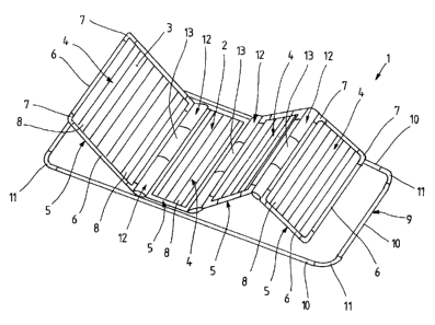
Figure 1 schematically illustrates in perspective view the bearing
construction 2 of a
bed 1. The bearing construction 2 is configured as a slatted base and provides
a
bearing surface 3 serving to support a mattress, a cushioning element or the
like.
CA 02653353 2008-11-25
8
The bearing construction 2 illustrated in the figure 1 can be supported in a
height-
adjustable fashion by a bearer frame not shown which is supported in turn by
load-
bearing rollers. The bearing construction 2 as such is designed as a slatted
base
and comprises segments 4 which are pivotable relative to one another. The
segments are carried by a supporting frame 9. Each segment 4 is comprised of a
frame 5, and each frame 5 is comprised of frame parts 6 which are connected to
each other by means of connectors 7. The slats 8 of the slatted base are
supported
by the respective frame 5. The slats 8 can be made for instance of wood,
plastic or
the like.
The supporting frame 9 of the bearing construction 2 also consists of frame
parts 10
which are connected to each other by means of corresponding connectors 11.
Both
the frame parts 6 of the frames 5 and the frame parts 10 of the supporting
frame 9
can be made of aluminum, for example in the form of extruded aluminum parts.
The
connectors 7 or 11 connecting the frame parts 6 or 10 are also made of
aluminum,
but it is also possible to use a plastic material for fabricating the
connectors 7 or 11.
The central segment 4, i.e. the second segment 4 from the left with respect to
the
drawing plane according to figure 1, is connected in a stationary fashion to
the
supporting frame 9. A pivoting device 12 (still to be described in more
detail)
according to the invention is flanged to the front face of the segment 4 on
both
sides. With reference to the sheet plane according to figure 1, a second
segment 4
joins the central segment 4 to its left. This second segment 4 can be also be
referred to as head part. The segment 4 which serves as a head part and the
segment 4 which serves as a central part are pivotable in relation to one
another, by
means of the pivoting device 12 interposed there between.
The segment 4 which is referred to as central part is joined to its right with
respect to
the drawing plane according to figure 1 by two additional segments 4. These
segments 4 are each arranged on the segment 4 which is disposed on the left
side
CA 02653353 2008-11-25
9
with regard to the drawing plane according to figure 1, so that they can be
pivoted
each in relation to this segment by the interposition of a pivoting device 12
according to the invention. All in all, a bearing construction 2 is formed
which
comprises four segments 4, and the individual segments 4 are pivotable in
relation
to one another thanks to these two pivoting devices 12 which are each arranged
between to neighboring segments 4.
Figure 2 illustrates the bearing construction according to figure 1, in a
schematic
lateral view. From this illustration, too the individual segments can be seen,
which
are adapted for pivoting in relation to one another, thanks to the pivoting
device 12
which is interposed between two neighboring segments each.
The pivoting device 12 which is arranged between two segments each is
schematically illustrated in the figure 3.
As shown by the figure 3, a pivoting device 12 each comprises a drive device
13
which is disposed on the face side between two neighboring segments ¨ as
already
explained in connection with the figures 1 and 2. The drive device 13
comprises a
motor 14 and a gear transmission 15. The motor 14 and the gear transmission 15
are accommodated in a housing 16 which preferably is in a two-part
configuration
from plastic.
A Shaft 17 is flanged to the power output side of the gear transmission 15. In
the
embodiment according to figure 3, the shaft is composed of two semi-shafts 18
and
19, and the gear transmission 15 is mainly disposed centrally between the two
semi-
shafts 18 and 19.
The semi-shafts 18 and 19 each carry on the end side thereof a fixing flange
21
which serves to couple one of the two neighboring segments 4 to the pivoting
device
= CA 02653353 2008-11-25
12. These fixing flanges 12 are preferably designed as stud links that can be
pushed
into the hollow frame parts 6 of the frame 5 and fixed therein.
Figure 3 further shows that the drive device 13 is connected to a fixed bearer
element 22. This bearer element 22 is composed of two segments 23, and the
drive
device 13 is arranged mainly centrally between these two segments 23.
Preferably, these segments 23 each constitute a housing 20 in which the
respective
associated semi-shafts 18 or 19 are supported for rotation.
The segments 23 each carry on one end thereof a neck flange 24, by which the
pivot device 12 can be mounted to a second segment. The neck flanges 24 just
as
the fixing flanges 21 are preferably formed as stud links which can be pushed
into
the hollow frame parts of the associated frame 5 of the segment 4 and fixed
there,
for arranging a segment 4 on the pivot device 12.
The pivot device 12 serves to interconnect two segments 4 for pivoting in
relation to
one another. The fixing flanges 21 serve for arranging the first segment,
whereas
the neck flanges 24 are provided for arranging the second segment. Upon
operation
of the pivoting device, the fixing flanges 21 are relatively pivoted with
respect to the
neck flanges 24, whereby the segment 4 supported by the fixing flanges 21 is
relatively pivoted with respect to the segment 4 supported by the neck flanges
24.
The pivoting device 12 as illustrated in figure 3 is disposed on the face side
between
two neighboring segments 4, as it can be seen from the figures 1 and 2, thus
achieving a particularly space-saving design of the entire bed construction.
Any
additional connecting rods like those known from prior art are not required.
Thanks to the encapsulated design of the pivot device the same is protected
against
splash water. The drive device 13 is preferably operated by means of a remote
CA 02653353 2008-11-25
. ,
11
control which can be of the wired type or wireless type. Preferably, one of
the two
segments which are coupled through a common pivoting device 12 are arranged
for
longitudinal displacement with respect to the pivot device 12, so that a
variation of
length is possible with respect to the bearing surface 3 provided by the
segments 4.
Accordingly, a variation of length of the mattress placed on the bearing
surface 3
occurring as a result of a pivoting movement can be compensated.
The basic principle of the pivot device according to the present invention has
been
explained above with reference to the schematic illustrations in the figures
1, 2 and
3. In the following, the pivot device according to the invention will be
discussed by
way of exemplary embodiments. A first embodiment is shown in the figures 4 to
20,
a second embodiment in the figures 21 to 36, a third embodiment in the figures
37
to 43, a fourth embodiment in the figure 44, a fifth embodiment in the figure
45, a
sixth embodiment in the figure 46 to 50, and a further embodiment in the
figures 51
to 60. In these figures, same and/or similar parts are identified by the same
reference numbers.
Figure 4 shows in a first embodiment a drive device 13 which comprises a motor
14
and a gear transmission 15. The motor 14 and the gear transmission 15 are each
accommodated in a housing.
Figure 5 shows a partial sectional view of the drive device 13 according to
figure 4,
taken along cutting line V-V. Figure 5 shows in particular the structure of
the gear
transmission 15.
Figure 6 shows a perspective view of the drive device 13 according to figure
4.
Figure 7 shows a lateral view of the drive device 13 according to figure 4,
namely in
a viewing direction from the left with respect to the drawing plane of figure
4.
CA 02653353 2008-11-25
12
Figure 8 shows a detailed view of the drive device 13 according to figure 5,
wherein
particularly the structure of the gear transmission 15 is visible.
The gear transmission 15 in a first embodiment according to figure 8 is a four-
stage
gear mechanism. The gear transmission 15 comprises a ring gear 25 on one side
and gears 26 meshing with said ring gear on the other side. The gears 26 form
the
gear stages in a manner which is known per se.
The ring gear 25 and the gears 26 are arranged inside a transmission case 27.
On
the power output side, a shaft 17 is provided which is in a power-transmitting
connection with the gears 26.
The tooth geometry of the gear transmission 15 is such that all gear stages
have the
identical internal toothing. The ring gear 25 accommodates all the components
and
serves as a case. The geometry of the first three gear stages is identical.
The gear transmission 15 according to figure 8 is a so-called planetary gear
transmission, wherein the sun gears and the planetary carriers form one
component
assembly. For easy manufacturing, the sun gears are pressed into the
respective
carrier discs. The high torques that must be transmitted do not allow a
cylindrical
interference fit assembly. For this reason, the sun gear profile in the disc
is
produced by punching or laser. The shaft is supported by means of an
encapsulated
roller bearing 28 because of the following advantages: low cost and low space
requirement; no axial forces and/or transverse forces; extremely low output
speed;
and the shaft is additionally supported via the planetary gears.
Figure 9 shows a perspective view of the gear transmission 15 according to
figure 8,
wherein particularly the individual gears 26 and the planar discs 29
separating the
gears from each other can be seen.
CA 02653353 2008-11-25
13
The ring gear 25 and an exemplary planar disc 29 are shown in detail in the
figures
10, 11, 12 and 13.
Figure 8 further shows that the gear transmission 15 is closed on the motor
side by
means of cap 30. The cap 30 is shown in detail in the figures 14, 15 and 16.
Figure 17 shows the motor 14 which is flanged to the gear transmission 15
according to figure 8, and in particular the design of the motor-side pinion
31.
The figures 18, 19 and 20 each show in a different view a planetary carrier
32,
wherein the figures 18 to 20 show the planetary carrier 32 of the final stage
of the
gear transmission 15 according to figure 8.
Figure 21 shows an exploded view of a second embodiment of the invention which
differently from the embodiment shown in the figures 4 to 20 is characterized
in that
a toothed belt is employed as a means for transmitting the motor power. The
toothed belt itself is not illustrated in figure 21, but the associated gears
26 can be
seen.
Figure 21 clearly shows the neck flanges 24 or the fixing flanges 21,
respectively.
The right neck flange 24 with respect to the drawing plane according to figure
21 is
shown in a detailed view in the figures 22, 23, 24 and 25. The left fixing
flange 21
with respect to the drawing plane according to figure 211s shown in a detailed
view
in the figures 26, 27 and 28.
For coupling the fixing flanges 21 to the respectively associated semi-shafts
18 or
19 of the shaft, a connecting part 33 is used in the embodiment according to
figure
21. This connecting part 33 is shown in detail in the figures 29, 30, 31 and
32. As
can be seen especially from the figures 29 and 30, the connecting part 33
consists
of a pin-like appendix 34 and a head 35. The head 35 carries on the periphery
CA 02653353 2008-11-25
14
thereof ribs 36 which run in the longitudinal direction and in the mounted
state
engage with corresponding teeth of the respectively associated fixing flanges
21, as
shown particularly by figure 21. A tooth belt gear 26, as it may be used for
example
in the embodiment according to figure 21, is shown in the figures 33, 34, 35
and 36.
A third embodiment of the pivoting device 12 according to the invention is
shown by
the figures 37 to 43.
Particularly the illustration according to figure 21 shows a motor 14 and a
gear
transmission 15 arranged inside a housing 16, the power being redirected to
the
shaft 17 by means of a gear arrangement 37. This gear arrangement 37 is shown
again in more detail in the figure 43. It can be seen from figure 43 that the
gear
arrangement 37 is comprised of two frontally meshing gears 26.
A different design of the gear arrangement 37 is shown by figure 44
illustrating a
fourth embodiment of the invention. According to this embodiment, three bevel
gears cooperate with each other, and each semi-shaft 18 or 19 carries a bevel
gear
38 on its end. These two bevel gears engage with a bevel gear 38 that is
flanged to
the gear transmission 15.
Figure 45 illustrates a further design of a gear arrangement 37 according to a
fifth
embodiment of the invention. According to this embodiment, a tetrahedron
sprocket
chain in the form of a parallelogram is employed for the transmission of
power.
A sixth embodiment of the invention is shown by the figures 46 to 50. The
distinctive
feature of this design results particularly from the compact structure of the
drive
device 13 which is accommodated inside the housing 16, as it can be seen
especially in figure 50. The particular advantage of this design is that the
downward
dimension of the drive device 13 with respect to the drawing plane according
to
figure 50 is rather small, so that the pivot device 12 according to the
invention can
CA 02653353 2008-11-25
be employed also in low beds. Moreover, according to this embodiment a spring
39
is arranged which serves to provide a basic load. The provision of such a
spring
advantageously allows the entire drive device 13, i.e. the motor 14 and the
gear
transmission 15, to have comparatively small dimensions.
The above description is merely exemplary and shall not be limiting in any
way.
Accordingly, it can be provided for instance that the pivoting device
according to the
invention not only includes a single motor. It can also include two motors,
for
instance in the form of a double motor. This is beneficial for the provision
of the
required adjustment force, especially in oversize beds.
A further embodiment is illustrated in the figures 51 to 60.
From the illustration according to the figure 51 is can be seen that also in
this
embodiment a bearing construction 2 is provided which is comprised of
individual
segments 4. The bearing construction 2 is supported by a supporting frame 9 in
the
manner which has already been described.
The distinctive feature of this embodiment according to the figures 51 to 60
are the
five segments which are provided for pivoting in relation to one another,
wherein
three segments 4 are coupled to each other via a common pivoting device 12.
As can be learnt especially from the figures 51 and 54, the bearing
construction 2
includes a central segment 4 which in its finally mounted state is arranged on
the
supporting frame 9 by means of two connecting rails 40 and in a stationary
fashion,
which means that the central segment 4 is not relatively pivotable with
respect to the
supporting frame 9.
The central segment 4 is joined by two additional segments to its left and to
its right
with respect to the drawing plane according to figure 51. The segments 4 which
are
. . CA 02653353 2008-11-25
16
arranged adjacent to the central segment 4 are movable relative to this
central
segment 4. The segments 4 arranged adjacent to the left side and the right
side of
the movable segments with respect to the drawing plane according to figure 51
are
again arranged for movement relative to the movable segments 4. The
adjustability
of the bearing construction 2 which results from the movable arrangement of
the
segments 4, i.e. the adjustability of the individual segments 4 relative to
one
another, are shown by way of an example in the figures 55, 56 and 58 to 60,
wherein the figure 60 merely illustrates the bearing construction 2, i.e. not
the
supporting frame 9 which supports the bearing construction in the finally
mounted
state.
Particularly the illustrations according to the figures 51 to 54 show that the
central
segment 4 and the segments 4 which are arranged to the left and to the right
of the
central segment with respect to the drawing plane according to figure 51, are
coupled to each other via a common pivoting device 12. This common pivoting
device 12 provides a double drive which includes a motor on one side and two
gear
transmissions on the other side. One gear transmission serves to the one
segment
4 arranged adjacent to the central segment 4, whereas the other gear
transmission
serves to the other segment 4 arranged adjacent to the central segment 4. As a
result of this construction one motor can be saved, because due to the common
pivoting device only one motor must be provided for totally three segments.
This not
only allows a low-cost design of the invention, but also easy handling and
less
mounting and maintenance work.
It can be clearly seen from the figures 58 to 60 that the pivoting device
according to
the present invention requires a comparatively small installation space, so
that a
compact, space-saving overall construction is achieved which can be
advantageously used also in low beds. Moreover, any connecting rods, cables or
other connecting and coupling means extending under the bearing construction
2,
i.e. under the individual segments 4, become unnecessary.
CA 02653353 2008-11-25
17
One embodiment of the invention employing a double motor at least for a
pivoting
device 12 is shown by the figures 61 to 68. A pivoting device 12, for which a
double
motor can be used, is for instance the pivoting device 12 of a central segment
4, as
this is shown by way of an example in the figure 51.
It can be seen particularly from figure 61 that the pivoting device 12
includes two
motors 14. Each motor 14 is flanged to an associated gear transmission 15
which is
connected in turn to an associated shaft 17 for power transmission. To
transmit
power between the gear transmission 15 on one side and the shaft 17 on the
other
side, an articulated lever 45 is used for example.
The figures 65 and 66 or 67 and 68 illustrate a neck flange 24 or a fixing
flange 21,
respectively.
As it can be seen from the figures 65 and 66, the neck flange 24 includes a
connecting section 42 which is attached to the segment 23 of a bearing element
22
in the finally mounted state, as this is illustrated particularly by the
figure 61. The
neck flange 24 also includes an elbow part 43. This engages in a hollow frame
part
6 of a segment 4 in the finally mounted condition, as this has already been
explained above. Similarly, the fixing flange 21 includes an elbow part 44, as
this
can be seen from the figures 67 and 68. In addition, a fixing flange comprises
a
shaft neck 41 which is also shown in the figures 67 and 68. In the mounted
state,
the shaft neck 41 engages in the associated semi-shaft 18 or 19 of a shaft 17
in a
power-transmitting fashion.
CA 02653353 2008-11-25
18
List of reference numbers
1 bed 32 planetary carrier
2 bearing construction 33 connecting part
3 bearing surface 34 appendix
4 segment 35 head
frame 36 rib
6 frame part 37 gear arrangement
7 connector 38 bevel gear
8 slat 39 spring
9 supporting frame 40 connecting rail
frame part 41 shaft neck
11 connector 42 connecting section
12 pivoting device 43 elbow part
13 drive device 44 elbow part
14 motor 45 articulated lever
gear transmission
16 housing
17 shaft
18 semi-shaft
19 semi-shaft
case
21 fixing flange
22 bearer element
23 segment
24 neck flange
ring gear
26 gear
27 housing
28 roller bearing
29 planar disc
cap
31 pinion