Note: Descriptions are shown in the official language in which they were submitted.
CA 02653522 2008-11-26
WO 2007/138283 PCT/GB2007/001954
COMMUNICATION APPARATUS AND METHOD
The present invention relates to an apparatus and method for communicating
over power cables. In particular, but not exclusively, the present invention
relates to a
method and apparatus for allowing detectors to communicate over existing, or
newly
installed power cables within buildings, such that if one detector is
triggered a signal
is transmitted alerting other detectors. The term "detector" includes, but is
not limited
to, smoke and/or heat detector, carbon monoxide detectors and security
detectors,
such as motion detectors.
As an example of the prior art, within domestic and cominercial buildings,
sinoke and heat detectors are commonly provided in order to detect a fire or
the risk
of a fire and alert people within the building. Typically, once smoke or
excessive heat
is detected at a first detector that detector triggers an alarm.
Alternatively, the first
detector may trigger some other device, such as turning on lights, or reinote
signalling, for exainple alerting the fire brigade.
Commonly, there is more than one detector per building. For instance, in a
large building there may be one detector in each room, or one detector per
group of
rooms. It will readily be appreciated that in such a scenario it may be that
only the
detector closest to the fire will detect a fire and trigger an alarn2. People
some
distance from the detector that detects the fire may not hear the alarm.
There is a recognised requirement for communication between smoke/heat
detectors, such that once a first detector detects a fire other detectors are
alerted
allowing their alarms to be set off, warning people in other parts of the
building. This
allows the warning of the fire to be spread more generally throughout the
building.
This may be particularly needed in a multi-occupancy building such as a block
of
flats.
At present, the usual method of providing this communication between
smoke/heat detectors is to provide dedicated wires between pairs of detectors.
Alternatively, radio frequency transinitters/receivers may be used to connect
a
network of detectors. However, such communication can be expensive to install
and
maintain.
Smoke/heat detectors are often connected to a mains electricity supply via
power cables within a building, allowing them to operate in standby mode for
1
CA 02653522 2008-11-26
WO 2007/138283 PCT/GB2007/001954
extended periods of time. Usually, a battery is connected to each detector to
act as a
backup in the event of the mains electricity supply being interrupted (either
when the
detectors are in a standby mode, or during a fire). The battery is typically
recharged
from the mains electricity supply via the power cable.
Cornmunications protocols that operate over mains electricity supplies are
known. This avoids the necessity of providing additional wiring, or radio
frequency
communications links, between devices that are already connected to a mains
electricity supply. However, such communications protocols are typically
synchronised to the mains electricity supply, and are therefore not suitable
for
communications between detectors. This is because the mains electricity supply
can
fail during a power cut and is often interrupted during fires, thus preventing
detectors
from communicating with each other.
It is an object of the present invention to obviate or mitigate one or more of
the
problems associated with the prior art, whether identified herein or
elsewhere.
According to a first aspect of the present invention there is provided a
communication apparatus for communicating over an electrical power cable,
comprising: a transmitter circuit adapted to transmit a communication signal;
and a
receiver circuit adapted to receive a communication signal from another
communication apparatus; wherein the communication apparatus is adapted to
transmit and receive communication signals over the power cable both when said
power cable is conducting electricity and when said power cable is not
conducting
electricity.
By allowing communications over power cables, even when the mains
electricity supply is interrupted, reliable communications between connected
devices
can be provided. This is particularly desirable for communications between
safety
critical devices such as smoke/heat detectors.
The electrical power cable may be adapted to conduct mains electricity.
Preferably, the communication apparatus is adapted to be connectable to a
device, the transmitter circuit being adapted to transmit the communication
signal in
response to an input control signal received from the device, and the receiver
circuit
being adapted to generate an output control signal indicative of whether a
communication signal has been received and transmit the output control signal
to the
device. Said device may be a heat or smoke detector.
2
CA 02653522 2008-11-26
WO 2007/138283 PCT/GB2007/001954
The cominunication apparatus may be adapted to be supplied with electrical
power by a battery contained within said device or said communication
apparatus.
Preferably, the communication signal comprises an amplitude shift keying
signal. Preferably, the amplitude shift keying signal comprises the presence
or
absence of a carrier signal at 108 kHz.
Preferably, the coinmunication signal comprises a Gold codeword. Preferably,
the transmitter circuit is adapted to cyclically transmit the Gold codeword.
Preferably, the transmitter circuit is adapted to wait for a predetermined
guard time
period before each transmission of the Gold codeword.
The communication apparatus may be adapted to transmit and receive only
one assigned Gold codeword. Alternatively, the communication apparatus may be
adapted to transmit and receive more than one assigned Gold codewords.
Preferably, the receiver circuit further comprises: an analog to digital
converter adapted to sample the communication signal and output digital
samples; and
a filter adapted to filter the digital samples.
Preferably, the receiver circuit further comprises: an amplitude tracker
adapted
to calculate the magnitude of each of a group of digital samples from the
filter; a mark
counter adapted to count the number of digital samples within the group having
magnitudes equal to or greater than a predetermined threshold; a space counter
adapted to count the number of digital samples within the group having
magnitudes
less than the predetermined threshold; a comparator adapted to output an
output signal
indicative of whether or not the mark counter exceeds the space counter; and a
buffer
adapted to store the output of the comparator.
Preferably, the buffer is adapted to store the output of the comparator for
each
of a predetennined number of groups of digital samples.
Preferably, the receiver circuit is further adapted to calculate the logical
exclusive OR of the contents of the buffer and the or each assigned Gold code,
and to
generate an output control signal indicative of the result of said
correlation.
According to a second aspect of the present invention there is provided a
method of communicating over an electrical power cable, the method
coznprising:
transmitting a communication signal; and receiving a communication signal;
wherein
said transmitting and receiving communication signals over said power cable
takes
3
CA 02653522 2008-11-26
WO 2007/138283 PCT/GB2007/001954
place both when said power cable is conducting electricity and when said power
cable
is not conducting electricity.
Preferably, transmitting a cominunication signal comprises: transmitting the
communication system in response to an input control signal; and wherein the
method
further comprises: generating an output control signal indicative of whether a
coinmunication signal has been received.
Preferably, transmitting a communication signal further comprises
transmitting an amplitude shift keying signal.
Preferably, transmitting a communication signal fiuther comprises
transmitting a Gold codeword.
Preferably, transmitting a communication signal further comprises
transmitting the Gold codeword cyclically.
Preferably, transmitting a communication signal farther comprises waiting for
a predetermined guard time period before each transmission of the Gold
codeword.
Preferably, receiving a communication signal comprises: sampling the
communication signal to generate digital samples; and filtering the digital
samples.
Preferably, receiving a communication signal further comprises: grouping a
predetermined number of consecutive digital sainples; calcuiating the
magnitude of
each digital sainple in the group; comparing the magnitude of each digital
sample in
the group to a predetermined threshold; incrementing either a mark counter or
a space
counter if the outcome of the said comparison is above or below the
predetermined
threshold respectively; comparing the mark counter and the space counter at
the end
of the group; and buffering the result of said comparison.
Preferably, receiving a coinmunication signal further comprises: buffering the
result of said comparison for each of a predetermined number of groups of
digital
samples.
Preferably, receiving a communication signal further comprises: computing
the logical exclusive OR of the buffered results of said comparison for each
of the
predetermined number of groups of digital samples and at least one assigned
Gold
code; and generating an output control signal indicative of the result of said
computed
logical exclusive OR.
According to a third aspect of the present invention there is provided a fire
detection system comprising: a communication apparatus for communicating over
an
4
CA 02653522 2008-11-26
WO 2007/138283 PCT/GB2007/001954
electrical power cable, the communication apparatus comprising: a transmitter
circuit
adapted to transmit a communication signal; and a receiver circuit adapted to
receive a
communication signal from another communication apparatus; and a fire detector
adapted to receive output control signals from the communication apparatus and
transinit an input control signal to the communication apparatus upon
detecting a fire;
wherein the transmitter circuit is adapted to transmit the communication
signal in
response to the input control signal, and the receiver circuit is adapted to
generate the
output control signal to indicate whether a communication signal has been
received,
the communication apparatus being adapted to transmit and receive
communication
signals over said power cable both when said power cable is conducting
electricity
and when said power cable is not conducting electricity.
Embodiments of the present invention will now be described, by way of
example only, with reference to the accompanying drawings, in which:
Figure 1 schematically illustrates a coinmunication apparatus for
communicating over power cables in accordance with an embodiment of the
present
invention, associated with a detector; and
Figure 2 schematically illustrates a signal detection algorithm for receiving
communications signals in accordance with an embodiment of the present
invention.
Embodiments of the present invention are described herein with specific
mention of their use in connection with smoke and/or heat detectors. The
present
invention is not limited to this, and is suitable for connecting any type of
detector, or
indeed any other device, over power cables.
It is known to send communications signals over power cables. X10 is an
industry standard protocol for communication between connected devices over
power
cables within domestic properties. XIO uses mains electricity power cables for
signalling and control purposes. X10 signals comprise short radio frequency
bursts
representing digital information. These bursts are synchronised to, and
transmitted
during, the relatively quiet periods around the zero-crossing points of a
domestic 50 or
60 Hz AC electricity supply.
However, the fact that X10 is synchronised to the zero-crossing points of the
AC waveform means that if the mains power supply is interrupted the Xl0
protocol
breaks down due to the transmitting and receiving units losing
synchronisation.
Furthemlore, X10 operates at a relatively high power. Without the mains
electricity
5
CA 02653522 2008-11-26
WO 2007/138283 PCT/GB2007/001954
supply, X10 communication would rapidly drain the power from any battery
backup
provided for a detector. X10 is also widely considered to be unreliable due to
its
susceptibility to blocking and interference caused by other electrical
equipment. For
these reasons, X10 is unsuited for use in communications between detectors.
A communication system in accordance with an embodiment of the present
invention allows smoke/heat detectors to communicate over existing mains
electricity
power cables within a building. In accordance with alternative embodiments of
the
present invention, the communication system can also work over other power
cables
that carry a DC or AC voltage power supply. The power cable supplies
electrical
power to the smoke/heat detector.
The term "power cable", as used herein is to be interpreted as an electrical
conductor, capable of supplying sufficient electrical power to act as a source
of
electrical power to connected devices. Thus, a cable carrying only a
conventional
communications signal would not fall within the definition of power cable for
the
present purposes.
Each detector may also have a battery to provide electrical power in the event
that the mains electricity supply is interrupted. If the detector has such a
back-up
batter, then typically the electrical power suppiied by the power cable is
arranged to
recharge the battery.
When a first detector has detected a fire or a risk of a fire, a communication
apparatus associated with the detector begins to transmit a communication
signal over
the power cable connected to that detector. The communication signal is
transmitted
either for a predetermined period or until the detector indicates that it no
longer
detects smoke or excess heat.
Each communication apparatus associated with a smoke/heat detector is
arranged to continuously listen for signals from other communication
apparatuses
indicating that a fire or a risk of a fire has been detected (for instance in
another part
of the building). As long as the transmitting and receiving communication
apparatuses remain connected via power cables (whether or not the power cables
continue to carry electrical power) transmitted signals will be detected. If
appropriate,
a connnunication apparatus receiving such a signal can also trigger the alarin
of an
associated detector, or take any other predetermined action.
6
CA 02653522 2008-11-26
WO 2007/138283 PCT/GB2007/001954
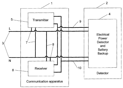
Referring now to Figure 1, this schematically illustrates a communication
apparatus 1 in accordance with the present invention. The communication
apparatus 1
is associated with a detector 2, for instance, a smoke/heat detector 2.
Smoke/heat
detector 2 may be entirely conventional, and as such will not be described in
fut-ther
detail.
In a preferred embodiment of the present invention, the communication
apparatus 1 coinprises a modular component, arranged to slide into a standard
push fit
connection in a smoke/heat detector 2, such that the communication apparatus 1
fits
between the smoke/heat detector 2 and a ceiling mounting.
The component parts of the communication apparatus 1 are typically
integrated into a single programmed microprocessor. However, the present
invention
is not limited to any particular physical implementation. The component parts
of the
communication apparatus are mounted on a printed circuit board. Connected to
the
printed circuit board are metal pins, which protrude through a plastic
housing. Upon
connection to the smoke/heat detector 2, the metal pins electrically couple
the
cominunication apparatus 1 to the detector 2, such that electrical power and
communications signals can be transferred.
The communication apparatus I is arranged such that it interfaces with
standard terminals provided on detector 2 for providing electrical power to
the
detector from a mains electricity power cable and for passing communications
signals
indicating that the detector has detected a fire, or that another detector has
detected a
fire. The detector 2 may be such that it can connect to an existing form of
communication apparatus, which communicates with other detectors over
dedicated
communication links. Such an existing detector need not be modified, and
operates in
the same way as before, when associated with a communication apparatus 1 in
accordance with an embodiinent of the present invention.
Figure 1 further illustrates the mains electricity power cable 3 supplying
power
to the detector 2, depicted as a live wire L and a neutral wire N. An earth
wire (not
illustrated) may also be provided. The power cable 3 extends through the
communication apparatus 1 and connects to the detector 2. The detector 2
comprises
a rechargeable battery 4 (and also an electrical power detector, arranged to
detect
whether power cable 3 is supplying electrical power). Battery 4 is charged
from the
7
CA 02653522 2008-11-26
WO 2007/138283 PCT/GB2007/001954
mains electricity supply when this is connected via power cable 3, in a
conventional
manner. Battery 4 in turn powers the operation of the detector 2.
Communication apparatus 1 comprises a transmitter circuit 5 and a receiver
circuit 6. Alternatively, the transmit and receive functions of the present
invention can
be integrated into a single transceiver circuit. Transmitter circuit 5 and
receiver circuit
6 are arranged to transmit and receive communication signals to and from the
power
cable 3 respectively. As such, both the transmitter circuit 5 and the receiver
circuit 6
are connected to the power cable 3 by connectors 7 and 8 respectively.
Connectors 7
and 8 may comprise wires.
Power is supplied to the transmitter circuit 5 and the receiver circuit 6 from
-battery 4 via a DC power cable 9. As an alternative, power for the
communication
apparatus 1 may be supplied directly from the power supply cable 3 when the
mains
electricity supply is connected. As a further alternative, the communication
apparatus
1 may further comprise another battery to supply the communication apparatus
with
power. This further battery may be in place of, or in addition to, the battery
within the
detector.
Transmitter circuit 5 and receiver circuit 6 are connected to the detector 2
by a
control connector 10. Control connector 10 may comprise a control wire. When
detector 2 detects a fire, a control signal is passed to the transmitter
circuit 5 via
control wire 10, activating transmitter circuit 5 to transmit the
communications signal
to other communication apparatuses 1 connected to power cable 3. As will be
described in greater detail below, the transmitter 5 is arranged to cyclically
transmit
the control signal, with gaps (or guard intervals) between each transinission.
Conversely, receiver circuit 6 is arranged to listen for communications
signals
transmitted by other communication apparatuses 1 on power cable 3. When
receiver
circuit 6 receives such a communications signal, it sends a control signal to
the
detector 2 via control wire 10 such that the detector 2 can take a
predetermined action,
such as to trigger an alarm.
The transmitter 5 is triggered by a non-zero DC signal supplied via control
wire 10, originating from the detector 2. This activates the transmitter to
send the
communication signal. This state of operation is called a "local alarm". The
transmitter remains in the local alarm state until the DC signal on control
wire 10 is
removed by the detector 2. When the receiver 6 receives a communication signal
8
CA 02653522 2008-11-26
WO 2007/138283 PCT/GB2007/001954
from another communication apparatus, it sets a non-zero DC voltage control
signal
on control wire 10. When the control signal is detected on control wire 10 by
the
smoke/heat detector, an alarm sound is activated by the detector, in a
conventional
inanner. This state of operation is referred to as a "remote alann" state.
In certain embodiments of the invention, the cominunication signal ttansmitted
by each communication apparatus on power cable 3 is arranged to be detectable
by
other coinmunication apparatuses within at least IOOm of power cable of the
transmitting coinmunication apparatus by providing sufficient signal
transmission
power to the transmitters together with robust specialised signal processing,
(described below). The system may include any number of communication
apparatuses, arranged to receive the communication signal.
The communication signal transmitted by a communication apparatus
indicating that sinoke or excess heat has been detected comprises a
periodically
repeated Gold code. A Gold code is a class of error correcting codes in
information
theory, which is a binary sequence chosen for its good correlation properties
for a
cyclic transmission. A Gold code comprises a set of Gold codewords. A Gold
codeword within a set of n Gold codewords, if correlated with every Gold
codeword
in the set, has a high correlation only with itself, and minimal correlation
with the
remaining n-1 codewords. This property of Gold codes still hold true even if
any bits
in a given codeword are inverted due to the effects of noise in communication
channels. This key property of Gold codes enables unique identification of
each
communication signal, such that a detector will only trigger another if its
unique
identification perfectly matches the codeword even in noisy communication
channel
conditions. In an einbodiment of the present invention the length of each Gold
codeword is 31 bits.
Each communication apparatus has an adjustable 4-bit address. This address
can be set for each communication apparatus 1. For instance, each
communication
apparatus 1 can further comprise 4 manually set dipswitches on the
communication
apparatus 1. The positions of the dipswitches are interpreted by a
coinmunication
protocol to correspond to a particular stored address. In an embodiment of the
present
invention, each address corresponds to one of 16 different 31 bit long Gold
codewords. The choice of Gold codeword length is a compromise between system
complexity and detection accuracy in noisy channel conditions. It is possible
to use
9
CA 02653522 2008-11-26
WO 2007/138283 PCT/GB2007/001954
Gold codewords that are longer or shorter than 31 bits in variants of this
communication apparatus. If more than 16 addresses are needed, then further
dipswitches may be provided.
Each communication apparatus is arranged to only respond to a received
communication signal if it is the saine Gold codeword as that set within the
coinmunication apparatus. In this way zones of smoke detectors can be created
such
that if one detector detects a fire only certain other detectors prograrnxned
with the
same Gold code will sound the alann. This may have particular utility in
domestic
properties as, otherwise, smoke detectors in neighbouring properties could be
triggered by a detected fire in a first property (due to the neighbouring
properties
being within the minimum transmission range along the power cable of IOOin).
As
discussed above, each detector could be arranged to detect two or more Gold
codewords, for instance to respond to fires in its own zone and immediately
adjacent
zones. A communication apparatus can either be in a transmission or a
reception
mode. In the case that two communication apparatuses transmit at exactly the
same
time, this will cause interference within the 100m range of each communication
apparatus. However this is unlikely, as each transmitter does not continuously
transmit Gold codewords without interruptions. Between consecutive
transmissions of
codewords there is sufficient guard time period, greater than the length of a
Gold
codeword, in terms of time. This guard time period has been found to give a
sufficient
safety level to avoid collision in case two apparatuses are both transmitting.
If the transinitted Gold codeword is interrupted then communication
apparatuses previously receiving the communication signal will stop carrying
out the
action associated with the signal (e.g. in the case of a smoke/heat detector
the alarm
will stop). However, the system is resilient in the face of noise and short
interruptions
of the signal.
The Gold code sequence is transmitted between the communication
apparatuses using amplitude shift keying (ASK). In this modulation scheine,
either a
carrier frequency is present or absent. The presence of the carrier frequency,
for a
single time period, corresponds to a transmitted `1' and its absence
corresponds to a
`0'. Thus, in each time period, the modulation scheme transmits a single bit
of
information. In a preferred embodiment of the present invention the carrier
frequency
used is 108 kHz. This frequency is chosen as it falls within an unregulated
frequency
CA 02653522 2008-11-26
WO 2007/138283 PCT/GB2007/001954
band, available for public unlicensed use. In alternative embodiments of the
present
invention, it is possible to use other carrier frequencies, for instance
frequencies that
fall within an unlicensed frequency band between 95kHz and 125 kHz.
Each receiving communication apparatus is arranged to synchronise itself to a
received cominunication signal, based upon a known duration of each bit. The
receiver 6 initially expects to receive a preamble of altemating `1's and `0's
before
every Gold codeword. The length of this alternating binary sequence is known
to the
receiver. Therefore, until the receiver detects the full preamble, it ignores
the
associated Gold codeword. If the receiver fails to detect the full preamble on
its first
attempt, it has another opportunity after the first Gold codeword to receive
the full
preamble, when the codeword is next transmitted by the transmitter. The length
and
the duration of the preamble can vary depeziding on the particular embodiment
of the
cominunication apparatus. Once a full preamble is detected by the receiver, an
absolute time reference is assigned to the beginning of the Gold codeword.
Once the
receiver establishes this time reference, it can then uniquely identify which
bit of the
Gold codeword it receives.
As described above, detectors are typically already provided with batteries
recharged from the mains electricity supply. As such, the communication
apparatus
can be powered by the battery in the event of the mains electricity supply
being
interrupted.
There are three main types of noise that can affect signal detection for
cominunications between power cable communication apparatuses in accordance
with
an embodiment of the present invention: amplitude noise, frequency noise and
phase
noise.
Amplitude noise in the system originates, for instance, from the following
sources: additive noise of the mains power cables (e.g. from dimmer switches
and
mains powered equipment), impedance variations on the power cables and noise
generated within the communication apparatus, e.g. within the microprocessor.
Frequency noise is due to variation in the timing circuit inside the
microprocessor for the transinitter and receiver and ambient temperature
variations,
Phase noise is a consequence of inductors in the system causing electrical
noise if any electromagnetic interference is present.
11
CA 02653522 2008-11-26
WO 2007/138283 PCT/GB2007/001954
The impact of noise on the communication signals transmitted on the power
cables is minimised due to the design of the signal detection algorithm, which
will
now be described with reference to Figure 2. The signal detection algorithm 21
(referred to herein as MSAC - Mark Space Amplitude Comparison) consists of
four
key components. Figure 2 depicts the process of signal detection and recovery
within
the receiver circuit.
After appropriate input filtering to reduce amplitude, frequency and phase
noise (not shown) the analog input carrier waveform 22 passes through an 8-bit
analog to digital converter 23. The output of the ADC 23 is passed to a
digital Finite
Impulse Response (FIR) band pass filter stage 24, which has a narrower pass
board
than external analogue band-pass filters. The output of the FIR filter is
processed by a
MSAC block 25 as shown in Figure 2.
The operation of the MSAC block 25 is shown in greater detail by blocks 27,
28, 29 and 30. Amplitude tracker 27 calculates the magnitude of each of a
group of
incoming sample from the ADC 23. The size of the sample group can be varied
depending on the particular implementation. In a preferred embodiment of the
present
invention, the group is large enough to last half a bit period. As such, the
size of the
group is dependent upon the ADC 23 sampling frequency and the bit frequency of
the
communication signal.
The inagnitudes of each sample in the group of ADC samples are passed
simultaneously to mark counter 28 and space counter 29 blocks to be compared
to a
pre-determined threshold. If a sample magnitude is greater than the threshold,
the
mark counter 28 is incremented by one; else the space counter 29 is
incremented by
one. The pre-determined threshold can be calibrated according to the amplitude
noise
present on the mains electricity supply for a specific implementation of a
coirununication system in accordance with an embodiment of the present
invention.
This is necessary as the counter values will vary according to the amplitude
of the
incoming analogue input waveform 22.
At the end of each sample group, the mark counter 28 and the space counter
29 counter values are passed to a comparator 30. The output of the comparator
30 is a
`1' if the mark counter 28 content is greater than the Space counter 29
content.
Otherwise, it is a`0'. The binary output of the comparator 30 is stored in the
hard
decision buffer 26, which stores the sequence of bits of a Gold codeword. The
size of
12
CA 02653522 2008-11-26
WO 2007/138283 PCT/GB2007/001954
this buffer depends on the Gold codeword length that is used and is chosen as
31 bits
in a preferred embodiment of this invention.
As discussed above, each codeword is preceded by a fixed length preamble of
alternating 'I's and `0's. In embodiments of the present invention this
preamble is not
stored in the hard decision buffer. Once the hard decision buffer has received
the full
codeword (that is once the buffer contains the correct number of bits - 31
bits in
certain einbodiments of the present invention) the receiver 6 correlates the
content of
the hard decision buffer 26 with the Gold codeword assigned to that
cominunication
apparatus. The correlation is performed by computing the logical exclusive OR
(XOR) of the locally stored Gold codeword and the content of buffer 26. If the
result
of the XOR operation is `0', then the correct Gold codeword has been received.
Otherwise, a different codeword has been received.
In alternative embodiments of the invention, the correlation of the content of
the hard decision buffer 26 with the Gold codeword assigned to that
communication
apparatus is adapted to determine whether the Gold codeword has been received,
even
if a proportion of the received codeword is corrupted. Due to the intrinsic
properties
of Gold codes, embodiments of the present invention are able to correctly
identify if a
Gold codeword has been received even if up to 30% of the 31 bits have been
reversed.
This is because the 16 chosen Gold codewords are chosen to be as mutual
different as
possible.
Each transmitted Gold codeword is preceded by a synchronisation preamble
that consists of alternating `1's and `0's of a constant length. The preamble
always
starts with a 1. The length of this preamble can vary depending on the
particular class
of Gold codewords used. In a preferred einbodiment of this invention, the
preamble
length is chosen as 10 bits. This is arranged to be greater than the maximuin
number
of alternating `1's and `0's in any of the 16 Gold codewords chosen in the
described
embodiinent of the invention. The receiver attempts to detect all 10 bits of
the
preamble first in order to establish a reliable time reference for the Gold
codeword. If
the receiver cannot synchronise to the full preamble on its first attempt, it
keeps on
retrying and is able to synchronise on consecutive attempts (during later
transmission
of the communication signal). Detection of the preamble works in the same way
as the
detection of a Gold codeword (as described above). Once the preamble is
detected, the
13
CA 02653522 2008-11-26
WO 2007/138283 PCT/GB2007/001954
absolute timing reference is acquired for calculating a symbol period for the
detection
of the successive Gold codeword.
Due to variations in the attenuation levels along the power cables between
smoke/heat detectors, the received peak-to-peak voltage at the analog waveform
input
for the microprocessor may not vary fully between OV and VDD (the maximum
possible input voltage of the ADC 23). This directly affects the dynamic range
of the
sampled values at the output of the ADC 23. This variation in the dynamic
range has
an impact on the threshold used in mark counter 28 and the Space counter 29.
This is
because the optimum decision threshold may move up and down changing the
confidence in making accurate bit decisions. The threshold can therefore be
fine
tuned experimentally for installed communication apparatuses and left
unchanged
once the optimum threshold has been found.
Advantageously, the signals transmitted by the communication apparatuses are
arranged to jump between different power cable circuits within a building. For
instance, the signals may jump between a lighting mains circuit and a power
outlet
circuit. Such transfer of the signal occurs at a transformer serving the
building.
Alternatively, a capacitive bridge between different power circuits may be
provided to
ensure optimum coupling, and hence optimal transmission of the communications
signal.
In order to prevent the communications signals leaving a local area (for
instance leaving the building in which the smoke/heat detectors are installed)
a filter,
for instance an inductive filter, may be provided.
Although the present invention has been described above with reference to
cominunication between heat/smoke detectors, it will be readily apparent to
the
appropriately skilled person that the present invention may be equally
applicable for
communication between other devices connected to a mains electricity supply.
Furthermore, although the above-described preferred embodiment of the
invention comprises a system in which only a single item of information can be
conveyed (i.e. whether or not a smoke/heat detector has been triggered), the
invention
is not limited to this. Specifically, in the above-described embodiment, each
communication apparatus is arranged to detect whether a single Gold codeword
assigned to that communication apparatus is received froin the power cable.
However, in an alternative embodiment of the present invention, each
communication
14
CA 02653522 2008-11-26
WO 2007/138283 PCT/GB2007/001954
apparatus could be arranged to detect two or more Gold codewords of the
present
invention, with the receipt of each Gold codeword triggering different
actions.
Alternatively, communication apparatuses in accordance with embodiinents of
the present invention could be arranged to transmit and receive a series of
concatenated Gold codes. The concatenated Gold codes could be transmitted
once, or
cyclically. A particular series of Gold codewords may indicate a particular
operation
for the device associated with that communication apparatus.
In the above described preferred embodiment, there are 16 different Gold
codewords, each 31-bits long. Each communication apparatus is arranged to
transmit
or receive a single Gold codeword set for that communication apparatus by
manually
setting four dipswitches. However, the present invention is not limited to
this. For
instance, the Gold codewords may vary in length, and/or there may be a
different
chosen number of Gold codewords. For instance, it may be necessary to increase
the
length of the Gold codewords if more Gold codewords are used, in order to
maintain
the required level of difference between each Gold code (required for robust
detection
of particular Gold codewords in a noisy environment). Multiple communication
apparatuses may be arranged to detect and receive the same Gold codewords.
Each
communication apparatus may be arranged to transmit only a single codeword,
but
arranged to receive multiple codewords. Each communication apparatus could be
arranged to transmit or receive any number of Gold codewords.
The transmitted signal has been described above as being a continuous cyclic
signal. However, the signal could be an intermittent signal of varying length
and
varying Gold codewords. In intermittent signalling, the transmission of a Gold
codeword is preceded by a period of inactivity where no transinission takes
place.
Tntennittent signalling is more power efficient than continuous signalling and
can
yield significant power savings at the transmitter. For instance, one
communication
apparatus may send an alternating calibration signal to cause all of the other
communication apparatuses to go into a calibration mode wherein the devices
automatically adapt their operation to account for variations in the
communication
channel or the operating environment. For instance the threshold within the
mark
counter 28 a.nd the space counter 29 may be adjusted in order to optimally
detect the
calibration signal.
CA 02653522 2008-11-26
WO 2007/138283 PCT/GB2007/001954
Other modifications and applications of the present invention will be readily
apparent to the appropriately skilled person, without departing from the scope
of the
appended claims.
16