Note: Descriptions are shown in the official language in which they were submitted.
CA 02653740 2008-12-24
WO 2008/000075 PCT/CA2007/001142
INTEGRATED PLATFORM JOIST SYSTEM
FIELD OF THE INVENTION
[0001] The present invention relates to an integrated platform joist, an
integrated platform
joist system, and a method for assembling such a system.
DESCRIPTION OF THE PRIOR ART
[0002] Joist systems are used in the construction industry to span a distance
between
opposing walls and provide a structural support for a floor, a roof or other
platform. The joists
are spaced apart and support a decking that forms a sub-floor. Such joists can
be manufactured
from a variety of materials including softwood, wood based laminates, metals
and metal alloys.
[0003] Joists manufactured from a metal, in particular steel, may be
fabricated in an open-
web configuration or in a roll-formed configuration. Open-web joists consist
of spaced-apart
upper and lower chord members that are connected with truss members such as
steel rods.
Typically, open-web joists are coated or finished with a coloured primer. Roll-
formed joists are
generally shaped from sheet-steel and cold-formed into a shape, such as a C-
shape when viewed
in cross section. Other configurations may include the assembly of multiple
cold-formed
sections to form an I-shape section. Roll-formed joists can be made from hot-
rolled steel, cold-
rolled steel, metallic-coated sheet-steel, and/or painted steel. Such joists
are intended to be
located at spaced locations and provide point supports for the decking.
[0004] Traditionally, joist systems have required bridging of the upper and
lower chord
members to brace the joists laterally to resist twisting during, or after
installation. Sub-floors, or
roofing, or sheathing of various materials is then usually installed on top of
the joist system.
These joist systems sometimes require multiple fastening means, such as, for
example, a tongue
and groove joint between the sub-floor components, an adhesive to secure the
sub-floor to the
joist and a screw to hold the sub-floor in situ and a bolt a rivet or a weld.
[0005] Over the years, the building industry has introduced various types of
composite steel
concrete and \ non-combustible floor and roof systems in which the upper chord
members are
21654766.2
-I-
CA 02653740 2008-12-24
WO 2008/000075 PCT/CA2007/001142
embedded within a concrete slab. The concrete slab has both load bearing and
fire resistant
properties. Examples of such composite joist can be found in US Patent Nos.
5,941,035;
4,741,138; and 4,454,695 and US Patent Publication Number 2002/0069606 Al. A
composite
joist design permits the upper chord member of a joist to be designed with
less steel in
comparison with the non-composite system, since the concrete slab, when
properly bonded to the
upper chord member, provides additional load support for the floor or roof
system.
[0006] One of the major drawbacks of modern joist systems is that they require
substantial
time to erect. They are also dependent on the availability of skilled labour.
100071 It is an object of the present invention to obviate or mitigate the
above-mentioned
drawback.
SUMMARY OF THE INVENTION
[0008] Accordingly, the present invention provides a deck assembly comprising
a deck
assembly comprising a plurality of joists located side by side and each having
a web portion and
a deck portion integrally formed with the web portion. The deck portion
extending laterally from
the web portion and said joists being spaced from one another such that the
deck portions from a
continuous deck surface with said joists being connected to one another.
[0009] The adjacent joists, once assembled in nested engagement, may be
secured together
using fastening means. The fastening means may be selected from the group
consisting of a
screw, a nail, a bolt, an adhesive, a weld, a folded seam and a toggle lock.
[0010] The deck assembly may optionally comprise lower chord bridging to span
an open
area beneath the platform portion of the joist to provide structural rigidity,
and prevent the
platform from tortionally deforming.
100111 According to a further aspect of the present invention there is
provided a joist for use
in a deck assembly, said joist having a web portion integrally formed with a
deck portion that
projects laterally to one side of said deck portion and has a distal edge for
connection to an
adjacent joist, whereby said deck portion maintains said web portions of
adjacent joists in spaced
relationship and provides a continuous deck surface between said web portions.
21654766.2
-2-
CA 02653740 2008-12-24
WO 2008/000075 PCT/CA2007/001142
100121 Preferably, the joists of the deck assembly are manufactured from a
metal or a metal
alloy, or a plastics material. Alternatively, the joists may be manufactured
from a composite
material.
100131 The joists, when manufactured from a metal or a metal alloy, may be
formed by cold-
forming techniques. Alternatively, the joist may be extruded into a desired
shape when said joist
is manufactured from aluminium, a plastics material, or a composite material.
[0014] Preferred uses of the deck assembly in accordance with the present
invention include
flooring systems; sub-floor systems; transverse or longitudinal walkways;
stairway treads;
specialty floors, for example, raised floors for computer rooms, electronic
and other
manufacturing plants and the like and flat or pitched roof systems.
[0015) The present invention also provides a method for assembling a deck
assembly in
accordance with the present invention, which method comprises the steps of a)
intercalating one
or more male and female portions of an adjacent joist in nesting engagement to
form a seam and
b) closing the seam.
BRIEF DESCRIPTION OF THE DRAWINGS
100161 The features of the invention will become more apparent in the
following detailed
description in which reference is made to the appended drawings wherein:
[0017] Figure 1 is a sectional view of a joist for use in the deck assembly;
[0018] Figure 2 is a sectional view showing a deck assembly comprising two
joists of Figure
1;
[0019] Figure 3 is a sectional view of an alternative joist;
[0020] Figure 4 is a sectional view showing a deck assembly comprising two
joists of Figure
2;
[0021] Figure 5A to 5C show a sequence of a closure of a seam formed by
intercalating male
and female portions from adjacent joists;
21654766.2
-3-
CA 02653740 2008-12-24
WO 2008/000075 PCT/CA2007/001142
[0022] Figure 6 is a sectional view of a deck assembly in a stair
configuration;
[0023] Figure 7 shows a joist with reinforcing ribs;
[0024] Figure 8 is a sectional view of a further embodiment of joist;
[0025] Figure 9 is a sectional view of a yet further embodiment of joist;
[0026] Figure 10 is an enlarged view of a portion of the joist shown in Figure
8;
100271 Figure 11 is a view on the line XI-XI of Figure 10;
[0028] Figure 12 is a perspective view of a deck assemble utilizing the joists
shown in
Figures 1 to 11; and
100291 Figure 13 shows a deck assembly in accordance with the present
invention in a
specialty floor configuration.
[0030] In the figures, like numerals denote like parts.
DETAILED DESCRIPTION OF THE INVENTION
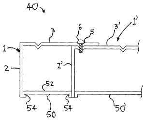
[0031] Referring to Figure 1, a joist 1 for use in a deck assembly 40
comprises a web portion
2 and a deck portion 3. It will be appreciated that the joists are of
indeterminate length L and
may be customized to the length required. The deck portion 3 extends outwardly
from the web
portion 2 and the included angle between the deck portion 3 and web portion 2
is typically 90 ,
although other angles may be incorporated. The deck portion 3 is provided with
a pair of V-
shaped recesses 4, 5 at spaced locations that are proximal to and distal from
the web portion 2
respectively. The joist I is formed from a rolled steel strip of appropriate
gauge and the joists 1
may be pre-finished by painting or powder coating to inhibit corrosion.
[0032] A plurality of joists 1, 1' of Figure 1 are assembled as shown in
Figure 2 to form a
deck assembly 40. The web portions 2, 2' of each joist are aligned vertically
in parallel with the
deck portions 2, 2' overlapping. The distal V-shaped recess 5 engages the
recess 4 to provide a
positive inter-engagement of the decking portions 3, 3". The joists 1, 1'are
joined together by
fasteners 6, such as self tapping screws or pop rivets to form an integral
unit. A lower chord
21654766.2
-4-
CA 02653740 2008-12-24
WO 2008/000075 PCT/CA2007/001142
bridge 50, 50' is located between upstanding portions of adjacent joists
spaced from the deck
portion to provide additional support and prevent tortional deformation of the
deck assembly 40.
[0033] The bridge 50, 50' has a planar body 52 with a pair of flanges 54 that
are secured to
the webs 2, 2'. The bridges 50 maintain the webs 2, 2" in spaced relationship
and provide a box
section to enhance the structural rigidity. The bridges 50 may be continuous
along substantially
the entire length of the joist I or may be relatively short lengths spaced
apart along the joist I to
provide rigidity of select locations.
[0034] The joists 1 may be added side by side to the deck assembly 40 to
provide a platform
of the required width and length. The individual joists are relatively light
to handle and assemble
but provide high strength and rigidity when in place. The joists 1 may be
fastened together with
mechanical fasteners, such as screws, bolts, clips or rivets, or may be
permanently connected, as
for example by welding. In typical applications for a residential deck, the
joists 1 are formed
from rolled steel strip having a thickness of between lmm and 3mm with 2mm
preferred. The
deck portion 3 has a lateral extent of typically 12 inches, although has up to
16" may be used
and the web has a height of between 3/2 inches and 8" with a preferred height
of 5'/2 inches. Fpr
such application, a length L of 12 feet has been found appropriate. The
dimensions may be
varied to suit the loading and the unsupported span as per normal engineering
practices.
[0035] The deck assembly 40 may be used as the final platform or may be used
to support a
non structural decking surface, such as slate, concrete or exotic hardwood.
The deck assembly
may also be used as a roof deck with a membrane bonded to the deck portions 3
after assembly.
[0036] Referring to Figure 3, an alternative design of a joist 1 of the deck
system is shown in
which like components will be identified with like reference numbers with a
suffix a added for
clarity. The joist 1 a comprises a web portion 2s and a deck portion 3a. One
end of the web
portion 2a includes a raised parapet structure 8 where part of the web portion
2a is bent back on
itself and projects above the deck portion 3a. The deck portion 3a extends
outwardly from the
parapet.
[0037] The distal edge of deck portion 3a has an upstanding rib 11 of
complimentary
configuration to the parapet 8 of an adjacent joist la of the deck assembly
40.
21654766.2
-5-
CA 02653740 2008-12-24
WO 2008/000075 PCT/CA2007/001142
[0038] The parapet 8 and rib 11 provide inter-engaging male and female
portions that are
exaggerated compared with the recesses 4, 5 in Figure 2 but perform a similar
function.
[0039] In use, the ribs 11, 11' of a first joist 1a intercalates with the
return portion 8 of
corresponding configuration on an adjacent joist la'. The resulting seam 12
formed by the
intercalating male and female portions is then secured together using a
suitable fastening means,
either mechanical or by welding.
100401 The joist 1 a are arranged, as can be seen at Figure 4 to define a deck
assembly 40a.
In this embodiment each joist 1 a,1 a' is interconnected in nested engagement
by intercalating the
parapet 8 with the rib 11 located on adjacent joists 1, 1'. Such intercalation
of male and female
portions results in an upstanding seam 12 which can be folded and swaged (see
Figure 5) as an
alternative to individual mechanical fasteners.
[0041] Figures 5A to 5C show a sequence of a closure of the seam 12. Figure 5A
shows the
open seam 12 formed by intercalating adjacent joists. A pneumatic seam closing
apparatus (not
shown) is used to fold the open seam in the direction of arrow A (Figure 5B).
This results in a
closed seam 13 that is impervious to the environment external of the deck
assembly and
inclement weather.
[0042] Figure 5C shows that the closed seam 13 of Figure 6B can be swaged to
reduce
material thickness at the closed seam. The closed seam 13 has been swaged in
the direction of
arrows B and B'.
[0043] As may be seen in Figure 6 where a suffix b is added for clarity, a
plurality of joists
lb, lb', lb" may be assembled in a stair-like configuration. Each joist lb,
lb', lb" has an
exaggerated web portion 2b, 2b', 2b" which is bent back on itself to form a
parapet 8b, 8b', 8b".
The deck portion 3b, 3b', 3b" of the joists lb extends substantially
perpendicularly outwardly
from the upstanding portions 2b, 2b', 2b". The parapet 8b, 8b', 8b" projects
above the deck
portion 3b, 3b', 3b"to form the individual steps of the stair-like deck
assembly 40b.
[0044] The deck 3b of the joists lb, lb', lb" are provided with V-shaped
recesses 5b as
shown in the embodiment of Figure 1. Similarly, the upper end face 10 of the
parapet 8b has a
V-shaped recess 4b formed to receive the recess 5b of the deck 3b. The height
of the web 2b
21654766.2
-6-
CA 02653740 2008-12-24
WO 2008/000075 PCT/CA2007/001142
will vary for each step and bridges may be incorporated between the webs to
interconnect them if
so required. The joists 1 are connected by fasteners as described above with
respect to Figure 1.
[0045] Figure 7 shows a joist lc with reinforcing ribs in the deck portion 3c.
The joist lc
comprises an upstanding portion 2c and a platform portion 3c extending
substantially
perpendicularly outwardly from the upstanding portion 2c. The platform portion
3c is provided
with a plurality of castellations 80. The castellations 80 provide additional
structural rigidity to
the deck 3c to prevent twisting of the platform 40c. The castellations 80 are
arranged parallel to
the longitudinal axis of the joist portion 3c, however, the ribs 80 can be
positioned perpendicular
to longitudinal axis depending on the application the deck assembly is being
used for.
[0046] It will be noted that the V-shaped recesses 4c, 5c are provided in the
deck portion 3c
adjacent the web 2c and distal edge of the deck 3c. The castellations 80 are
located between
recesses 4.5 to permit the units lc to be joined side by side.
100471 A further embodiment is shown in Figure 8 in which like reference
numerals will be
used to denote like component with a suffix d added for clarity. In the
embodiment of Figure 8,
each of the joists ld has a flange 60, 62 formed at the free edge of the web
portion 2d and the
deck portion 3d respectively. To form a continuous deck, the flange 62 is
butted against the web
of the adjacent unit ld with the decks aligned. The flange 62 may then be
secured to the adjacent
web 2a as described above. The flange 60 at the lower end of the web 2d
enhances the bending
stiffness of the joist and provides a bearing surface when the deck assembly
is located on a
support.
[0048] A similar arrangement is shown in Figure 9 in which a pair of webs 2e'.
2e" extend
perpendicularly from opposite edges of deck 3e. Each of the webs 2e', 2e"
terminates in a
flange 64. The deck assembly 40e is assembled by abutting the webs 2e', 2e"of
adjacent joists
1 e against one another and securing the webs 2e', 2e" by mechanical fasteners
or the like.
100491 The attachment of the adjacent units to one another is shown in greater
detail in
Figures 10 and 11, as applied to the embodiment shown in Figure 8. It will be
appreciated
however that a similar arrangement may be utilized in each of the embodiments
described above.
Referring therefore to Figures 10 and 11, a hole 90 is punched into the web
2e" and elongate slot
21654766.2
-7-
CA 02653740 2008-12-24
WO 2008/000075 PCT/CA2007/001142
92 punched into the web 2e'. The hole 90 and slot 92 are aligned permitting
limited fore and aft
adjustment between the two joists. A fastener 94 is inserted through the slot
and engages with
the hole 90. The fastener 94 is preferably self tapping so as to cut the
thread on the hole 90 and
pull the web 2e" up to and in abutment with the web 2e'.
[0050] To assist alignment of the units 1, each of the opposed portions of the
joists 1, either
the web portions or the deck portions may be formed with a registrar such as a
witnessed
deformations or dimples 96 that provide for registration of one unit against
another. Such an
arrangement assists in the rapid assembly and alignment of the deck assembly.
[0051] In each of the embodiments described above, it will be noted that the
joists may be
assembled to provide a continuous deck surface whilst providing integral
support for that surface
in the form of the webs. The deck assembly 40 may be used in a variety of
environments and
under different conditions. As illustrated in Figure 12, the deck assembly 40
may be utilized as
an elevated deck in residential or commercial environments. Referring
therefore to Figure 12, a
pair of posts 100, 102 support a beam 104 that extends generally parallel to
the face of a building
B to which the deck structure is connected. The beam 104 is dimensioned to
support the load
imposed upon the deck in the normal use and in accordance with the relevant
building standards.
It will also be appreciated that whilst a steel beam is preferred, a wooden
beam may be used with
the span adjusted accordingly.
[0052] The joists 1 are then assembled side by side to run perpendicular to
the beams 104.
The joists 1 are connected to one another through the fastening and enhanced
rigidity provided
by the bridges 50 that may extend either continuously along the length of the
joist I or extend
intermittently along the length.
[0053] The webs 2 of the joists I are secured to the beams 104 by clips or
other fasteners to
secure the joists.
[0054] Depending upon the cross section of the joists 1 that is utilized, it
may be necessary to
support the distal edge of the final unit with an additional web that may be
fastened to the distal
edge of the joist I and may be provided with an inter-engaging formation.
21654766.2
-8-
CA 02653740 2008-12-24
WO 2008/000075 PCT/CA2007/001142
[0055] During assembly of the deck assembly 40, each of the joists is
relatively easy to
handle due to the light weight construction. The joists 40 may be aligned and
interconnected
through the use of the inter-engaging formations and secured to one another by
fasteners, either
mechanical or permanent. Where necessary, the length of the units 1 may be
extended by joining
two joists end to end with an overlap between the ends of the joists over a
beam.
[0056] With the deck assembly 40 assembled, it is possible to utilize a
variety of finishes
providing increased flexibility in achieving the desired aesthetics. The deck
assembly 40 may,
for example, support tile, stone, slate, concrete, pavers, wood tiles or the
like. These may be free
floating on the deck surface or may be attached with adhesive or screws or the
like.
[0057] As may be seen in Figure 13, the deck assembly 40 using joists la as
shown in Figure
3 provides a recessed area into which cement or concrete or other filler or
substrate 100, 100' can
be poured. This is particularly useful when a raised floor is required in, for
example, special
equipment rooms. The cement or other filler serves to provide a durable
surface and also
provides structural support to the deck assembly by preventing twisting of the
platform structure.
The deck assembly is also provided with lower chord bridging 50, 50' to
further support the deck
assembly 40.
[0058] Although the joists have been described above in the context of
building a deck
assembly, it will be appreciated that a similar system may be used to provide
a flat roof of a
building or as an inclined roof with the rafters integrally formed by the
webs. The deck
assembly may also be used as a self supporting structural vertical wall.
[0059] Although described principally in a construction environment, the
product may also
be used in other horizontal application, such as the bed of a trailer, or in a
vertical application
such as a billboard.
[0060] In each embodiment, the webs 2 may be formed with predefined apertures
to
accommodate services being provided beneath the deck 3 and to minimize the
cutting necessary
at final installation. This enables the applied finish to be maintained after
installation and inhibit
corrosion.
21654766.2
-9-