Note: Descriptions are shown in the official language in which they were submitted.
CA 02653997 2009-06-30
1
FOLDABLE DISPLAY SYSTEM
Field of the Invention
The present description refers to an application for a patent of invention for
a display
receiving a series of assembly units, or assembly parts, each one basically
composed by two
foldable walls formed by a wrinkle, also in agreement by means of wrinkles
with two adjacent
walls, separated from each other by their free edges, being moved by a system
of tweezers,
being said assembly part liable to receive an elastic band through which it
will be fixed to
especially made grooves at pre-determined spots of the juxtaposed rims from
both parts forming
the display body.
Thus, the assembly part rests its foldable walls over the internal faces of
the parts
forming the display body and, by action of the elastic band, jointly with the
effect of tweezers
provided by the separate walls, said display is automatically opened, also
allowing it to close if
required.
Background of the Invention
Varieties of devices acting to form self-supporting displays are already known
in the
market and may be seen in documents such as BR 0,303,694-4, filed on August
14, 2003, BR
0,303,693-6, filed on August 14, 2003, BR 0,502,306-8, filed on June 21, 2006,
BR 0,505,915-1,
filed on December 27, 2005, FR Al 0106569, filed on May 18, 2001, and BR
0,007,143-9A, filed
on July 11, 2000. The latter one also mentions French documents such as FR-A-
2680030, FR-
A-2650907 and FR-A-2210317, while the document BR 0,201,711-3, filed on May
10, 2002, also
mentions other two French documents, namely FR 2,760,880 and FR 2,795,217.
In the case of document FR Al 0106569, a device formed by carton parts with
various
fitting and elastic elements is disclosed, including a set of details in the
form of grooves, folds,
wrinkles and others, working to allow the set to be practically automatically
assembled, so to
obtain a prismatic vertical structure with means to receive general
advertising.
Generally speaking, documents present devices having means to offer displays
with self-
supporting characteristics, i.e. to be automatically opened, working by means
of a generally
diagonal complementary internal structure, some of them elastically or
telescopically, liable to
be extended or retracted to assemble the set.
Concerning other documents, some of them with no internal complementary
structure,
we can see that all of them show devices obtained by means of semi-rigid parts
of carton,
projected with grooves, fittings, wrinkles, folds and other details allowing
to assemble the set.
CA 02653997 2009-06-30
2
Therefore, each one of the above devices presents constructive and functional
details
characterizing different solutions to overcome one or another disadvantage
over the existing
state of the art.
Thus, known devices present appropriate means to meet different purposes,
mainly to
form a self-supporting advertising display which is substantially vertically
elongated, and also
to allow to be sold (ex factory) fully disassembled or folded, substantially
facilitating its transport,
stocking and storing while not in use.
Despite accomplishing, in a way, proposed objects, such conventional devices
present
complex constructivity, also generating a range of equally complex assembly
details, resulting
in products with really very high cost and many of them also have an
internally located
complementary structural part to obtain the self-supporting condition, i.e.
the condition for its
automatic assembly.
Summary of the Invention
A defined embodiment for the device to be able to have a really simplified
construction
over conventional devices is proposed in the present patent application by an
assembling part
made of a square tubular body, formed by two walls which may be folded by a
wrinkle which,
from other wrinkles, agree with two separate walls by their juxtaposed free
edges. Said foldable
walls receive a pair of aligned higher and lower grooves each, into which an
elastic ring band
is fitted.
On the other hand, the display has junction rims for the two parts composing
its body,
folded and juxtaposed, both receiving identical grooves forming higher and
lower hooks, through
which the ends of the elastic ring band will be fitted as already fixed to the
grooves of foldable
walls of the assembly part.
Therefore, the already fixed assembly part rests by means of its foldable
walls to the
internal faces of both parts composing the body of the display, being
tensioned by the action of
the elastic band. Separate walls of the assembly part, on the other hand,
embrace each side
of the juxtaposed rims of said parts composing the display, acting as
tweezers, jointly to the
action of the elastic band.
Therefore, when both parts composing the display are pressed against each
other, i. e.
in the case of a closed display folded by its sections, the assembly part, by
operation of the
tweezers, also has its walls both foldable and separate, extended but
tensioned by the action
of the elastic band.
After unfolding and vertically positioning the display, its two parts get
slightly apart, just
enough for the elastic band, tensioned between the grooves of juxtaposed rims,
to open foldable
walls of the assembly part. When opened, foldable walls, jointly to the
separate walls acting as
CA 02653997 2014-07-10
3
tweezers, naturally force both parts composing the body of the display to get
apart, thus
obtaining their automatic assembly.
Assembly parts will be applied to as many units as required, always in pairs
and opposed
to the juxtaposed rims of the parts composing the body of the display.
Apart from quadrangular configuration, the assembly part may have triangular
configuration, as we will see below, so to allow quadrangular (rectangular or
even square)
displays to be formed, besides elliptical ones. Thanks to the system of
tweezers, the wrinkling
itself of juxtaposed rims of the parts composing the display may vary, so to
allow other
automatic assembly options for displays, both elliptical and quadrangular.
In accordance with an aspect of the present invention, there is provided a
display for an
automatic assembly system comprising a display formed by a front part and an
end part, both
the front part and the end part are provided with bends forming foldable
sections, the front part
and the end part are capable of receiving advertising printing, and are folded
lengthwise,
forming front flaps on each end of the front part and end flaps on each end of
the end part, the
front flaps and the end flaps comprise at a pre-determined spot a higher hook-
shaped groove
and an invertedly repeated lower hook-shaped groove; and an assembly part,
that is received
in the higher and lower grooves when the front flaps and end flaps are
adjacent, the assembly
part having a tubular body with a quadrangular cross section, formed by a wall
having three
bendable portions and two free ends, the free ends adjacent and spaced from
each other, the
three bending portions creating two foldable walls internal to the wall and
two adjacent walls at
the free ends, the foldable walls have a pair of vertical open grooves on each
of the higher and
lower periphery thereof that receive an elastic band.
Brief Description of the Drawings
Having been superficially explained, the display with its assembly part and
the involved
system are now better detailed by means of the attached figures. Figures as
listed below, from
1 to 8, refer to an ellipsoidal display, where juxtaposed rims of both parts
composing its body
are formed from a wrinkle, receiving the assembly part having, in this case,
quadrangular
configuration:
Figure 1 - Perspective view of the display showing, from its higher edge,
juxtaposed rims
from both parts composing its body;
Figure 2- Higher part of the display, with one of the parts composing its body
being cut,
showing juxtaposed rims with their higher and lower hook-shaped grooves, so to
receive the
elastic ring band to fix and tension the assembly part;
CA 02653997 2009-06-30
4
Figure 3 - Perspective view of a part of juxtaposed rims, which grooves
receive the
elastic ring band to fix and tension the assembly part. On its side, enlarged
detail A of the
assembly part with its foldable walls open, in a position to keep the display
as assembled;
Figure 4 - Plain view of the closed display. Under this condition, the walls
of the
assembly part extend jointly with both parts composing the body of the
display;
Figure 5- View as per previous figure, with both parts composing the body of
the display
being opened, when the foldable walls of the assembly part get apart thanks to
the action of the
elastic band and the effect of tweezers of its, separate walls;
Figure 6 - View of the display as already assembled. Below, enlarged detail B;
Figure 7 - Illustrative view showing the display in perspective being closed;
Figure 8 - View of the previous figure, showing the display as already closed;
Figures as listed below, from 9 to 14, refer to a quadrangular (rectangular)
display,
where the two parts composing its body receive two wrinkles each made shortly
from the
juxtaposition rims. In this case, the rims project from an intermediate point
in the display after
being assembled and receive the assembly part, which has, in this case, a
triangular
configuration;
Figure 9- Perspective view of the display showing, from its higher edge,
juxtaposed rims
from both parts composing its body, also formed from an intermediate point,
receiving the
assembly part, with triangular configuration;
Figure 10- Higher part of the display, with one of the parts composing its
body, showing
juxtaposed rims with their higher and lower hook-shaped grooves, so to receive
the elastic ring
band to fix and tension the assembly part, in this case in triangular
configuration;
Figure 11 - Perspective view of the two parts composing the body of the
display,
separately, showing hook-shaped grooves of juxtaposed rims, through which the
elastic ring
band will be fitted to fix and tension the triangular assembly part. On its
side, enlarged detail
C of the assembly part with its foldable walls open, in a position to keep the
display as
assembled;
Figure 12 - View of the closed display. The walls of the assembly part extend
jointly with
both parts composing the body of the display;
Figure 13 - View as per previous figure, with both parts composing the body of
the
display being kept apart through the opening of the foldable walls of the
assembly part, thanks
to the action of the elastic band and the effect of tweezers of its separate
walls. Below,
enlarged detail D;
Figure 14 - View of the display as already assembled;
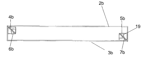
Figures as listed below, from 15 to 21, refer to a quadrangular (rectangular)
display,
where the two parts composing its body receive just one wrinkle, at a point
near just one of the
CA 02653997 2009-06-30
folds of its juxtaposition rims. The parts thus composed should be glued so
that their only
wrinkles remain inverted and juxtaposition rims are consequently projected in
opposition, one
at each opposed vertex from the quadrangular display;
Figure 15 - Perspective view of the two parts composing the body of the
display, each
5 one provided with one single wrinkle from just one of its juxtaposition
rims. When parts are
assembled, wrinkles position themselves, consequently in inverted position, at
opposed
vertexes, thus obtaining another kind of assembly;
Figure 16 - Perspective view of the display showing, from its higher edge, the
pairs of
juxtaposed rims from both parts composing its body, each one receiving its
corresponding
assembly part;
Figures 17 to 19- Perspective sequence showing the opening of foldable parts
from the
assembly part, by action of the tensioned elastic band between the grooves of
juxtaposed rims,
combined to the effect of tweezers as provided by separate walls. Said opening
will naturally
make both parts composing the body of the display come apart, automatically
opening it;
Figure 20 - View of the closed display. The walls of the assembly part extend
jointly with
both parts composing the body of the display;
Figure 21 - View as per previous figure, with both parts composing the body of
the
display being opened, when the foldable walls of the assembly part also open
thanks to the
action of the elastic band and the effect of tweezers of its separate walls.
Below, enlarged detail
E;
Figure 22 - View of the display as already assembled. In this view, we can see
inverted
rims thanks to the formation of the wrinkle, as effected at the cutting and
wrinkling step as per
the project.
Detailed Description of the Invention
In agreement with the attached drawings, the "IMPROVEMENT IN DISPLAY FOR
AUTOMATIC ASSEMBLY SYSTEM" object of the present application for a patent of
invention
is constituted by a display (1) of carton or another appropriate material,
presenting elliptical
crosswise section, formed by a front (2) and end (3) part, both provided with
crosswise wrinkles
(4) forming sections (5) for folding, being said parts liable to receive
advertising printing and
furthermore folded lengthwise at their ends, so to form, on part (2), rims
(4), (5) and, on part (3),
rims (6), (7).
For the intended system, rims (4), (5) and (6), (7) receive, at the cutting
and wrinkling
step, at pre-determined spots, preferably at each section (5), a higher hook-
shaped groove (8)
which, after a short free path (9), is invertedly repeated into a lower groove
(10).
CA 02653997 2009-06-30
6
Parts (2) and (3), after being assembled by means of juxtaposition of their
rims (4), (5)
with rims (6), (7), already containing their grooves (8) and (10) receive, at
their sections (5), at
least one assembly part (11) in a tubular body in quadrangular section, formed
by two foldable
walls (12) by a central wrinkle (13) which, after new wrinkles (14), project
two adjacent walls
(15), apart from each other, at their free edges (16).
The walls (12) receive a pair of grooves each, projected from their higher and
lower
edges, being therefore a higher vertical groove (17) and a lower vertical
groove (18), both
aligned and made in juxtaposition, receiving the introduction of an elastic
ring band (19). As
especially shown by detail A of Figure 3, the ring band (19) involves, through
grooves (17) and
(18), foldable walls (12).
Being thus the set constituted, the assembly part (11) installed in pairs has
its elastic
band (19) introduced, from its edges, between higher (17) and lower (18)
grooves of the
juxtaposed rims (4), (5) and (6), (7), so to rest their foldable walls (12) to
the internal faces of
both parts (2) and (3) composing the body of the display (1). On the other
hand, separate walls
(15) are anchored by their free edges (16) to the foldings of the rims (4),
(5) and (6), (7), so to
embrace them in the form of tweezers.
Therefore, when both parts (2) and (3) get close to close the display (1),
separate walls
(15), due to the effect of tweezers, allow the whole assembly part (11) to
extend, taking plain
condition but remaining strongly tensioned by the action of the elastic band
(19).
To open it, when the display (1) is positioned vertically, after slightly
taking apart both
parts (2) and (3), foldable walls (12) then tensioned, jointly to the effect
of tweezers from
separate walls (15), open, causing both parts (2) and (3) to naturally get
apart, thus
automatically assembling the display (1), as especially shown by Figures 4, 5
and 6.
The above description refers to an ellipsoidal display (1), when wrinkles are
made from
folding juxtaposition rims (4), (5) and (6), (7) themselves.
In the case of forming quadrangular or rectangular displays (1a), their two
parts (2a) and
(3a) receive a wrinkle (20) after each one of the rims (4a), (5a) and (6a),
(7a), keeping the same
system, to fix and tension assembly parts (11a). In this case, the parts (2a)
and (3a), after being
joined, form juxtaposed rims (4a), (5a) and (6a), (7a) projected from an
intermediate point in the
body of the sides (21) of the display (1a). Assembly parts (11), on the other
hand, after the
wrinkles (14), project coplanar walls (22), equally separated by their free
edges (16).
With such constitution, the part (11a) takes triangular shape and rests their
coplanar
walls (22) to the sides (21) of the body of the display (1), with free edges
(16) equally involving,
under the same system of tweezers, rims (4a), (5a) and (6a), (7a).
CA 02653997 2013-09-24
7
Finally, in another version, by using the same self-assembling system, both
parts (2b)
and (3b) composing the body of the display (1b) receive just one wrinkle (20),
at a point just
near one of the folds of its juxtaposition rims. Both parts (2b) and (3b) thus
composed should
be glued so that their only wrinkles (20) remain inverted, as shown by Figure
15, and
juxtaposition rims (4b), (5b) and (6b), (7b) are consequently joined,
projected in opposition, one
at each opposed vertex of the display (1b), causing its quadrangular shape.
According to the longer distance from the wrinkle (20) over juxtaposition rims
(4b), (5b)
and (6b), (7b), display (1 b) may progress from a rectangular shape to square
shape.