Note: Descriptions are shown in the official language in which they were submitted.
CA 02654223 2008-12-03
WO 2007/146227 PCT/US2007/013686
FLOW-INDUCED DELIVERY FROM A DRUG MASS
CROSS-REFERENCE TO RELATED APPLICATIONS
[01] This application claims the benefit of U.S. Provisional Application Ser.
No.
60/804,394 (attorney docket number 006501.00022), filed June 9, 2006 and
titled
"Drug Delivery by Flow Dissolution," hereby incorporated by reference herein.
BACKGROUND
[02] Use of drugs in combination with devices capable of tissue-specific
delivery poses
special problems for drug formulation. In some cases, the formulation should
be
stable over an extended period of time, especially if that formulation is
intended for
use in. an implanted drug delivery device.
SUMMARY
1031 This Summary is provided to introduce a selection of concepts in a
simplified form
that are further described below in the Detailed Description. This Summary is
not
intended to identify key or essential features of the claimed subject matter,
nor is it
intended to be used as an aid in determining the scope of the claimed subject
matter.
[04] At least some embodiments of the invention address problems posed by
tissue-
specific drug delivery devices. In at least some such embodiments, a solid
form of a
drug is stored in the device and delivered to a desired region using an
appropriate
vehicle. Embodiments of the invention also include preparing a solution (or
suspension) of a therapeutically effective concentration of a drug which is
sparingly
soluble in water, with the solution (or suspension) being formed by removal of
drug
from a mass of solid drug using an appropriate vehicle.
BRIEF DESCRIPTION OF THE FIGURES
1051 The following detailed description is better understood when read in
conjunction with
the accompanying drawings, which are included by way of example, and not by
way
1
CA 02654223 2008-12-03
WO 2007/146227 PCT/US2007/013686
of limitation. Some of the drawings include shading. Shading is provided only
for
the purpose of enhancing readability, and the presence or absence of shading
in a
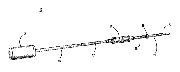
particular drawing is not otherwise intended to have significance.
[06] FIG. 1 shows a drug delivery device according to one embodiment.
[07] FIG. 2 is a cross-sectional view of a sleeved drug chamber from FIG. 1.
[08] FIGS. 3A through 3C are cross-sectional views of drug chambers including
screens.
[09] FIGS. 3D and 3E are perspective and cross-sectional views, respectively,
of a drug
chamber that includes an air vent.
[10] FIG. 3F is a perspective view of a drug chamber that includes flats.
[11] FIG. 4 shows a sleeved drug chamber joined to catheters and to a 3-D
antibacterial
filter.
[12] FIG. 5 is a cross sectional view of a solid drug and 3-D antibacterial
filter housing.
[13] FIG. 6 shows a subcutaneously-implantable port attached with a catheter
to a sleeved
drug chamber.
[14] FIG. 7 shows an open subcutaneously-implantable port containing pellets
of solid
drug.
[15] FIGS. 8 and 9 show a two piece solid drug and 3-D antibacterial filter
housing
according to another embodiment.
[16] FIG. 10 is a cross-sectional view of the sleeved drug chamber from FIG.
2, with
example dimensions included.
[17] FIG. 11 shows an embodiment in which a dual lumen tube extends from a
pump
and/or reservoir containing solid drug.
[18] FIG. 12 is an enlarged view of the distal ends of the dual lumen tube
shown in FIG.
11.
2
CA 02654223 2008-12-03
WO 2007/146227 PCT/US2007/013686
[19] FIG. 13 is a perspective view showing an embodiment in which a semi-
permeable
membrane allows interstitial fluid to pass into a chamber containing a solid
drug.
[20] FIG. 14 is a fully cross-sectional view of the embodiment of FIG. 13.
[21] FIG. 15 shows the embodiment of FIGS. 13 and 14 containing solid drug
pellets.
[22] FIG. 16 shows an embodiment where fluid is circulated unidirectionally
through a
loop containing a semi-permeable hollow fiber.
[23] FIG. 17 is an enlarged view of the distal end of the embodiment of FIG.
16, and
shows additional details of the hollow fiber loop.
[24] FIG. 18 is a cross-sectional view of the connection between the hollow
fiber and non-
permeable tubing of FIG. 17.
[25] FIGS. 19 through 22 show an embodiment implementing electrophoresis-
stimulated
delivery of drug.
[26] FIGS. 23 and 24 show an embodiment implementing magnetically-stimulated
delivery of drug.
[27] FIG. 25 is another embodiment implementing magnetically-stimulated
delivery of
drug.
[28] FIG. 26 shows the elution of gacyclidine from a drug dissolution chamber
as a
function of the concentration of hydrochloric acid in Ringer's solution used
to erode
pellets of crystalline gacyclidine base.
DETAILED DESCRIPTION
[29] At least some embodiments include methods for delivering a
therapeutically effective
concentration of a drug for which either the acidic or basic form of the drug
is water
insoluble or sparingly water-soluble. As used herein, a drug form is
"sparingly water-
soluble" if only an insignificant amount of that drug form can be dissolved by
water
alone. For a drug with acid-base functional groups, a less water-soluble form
is likely
3
CA 02654223 2008-12-03
WO 2007/146227 PCT/US2007/013686
to be more stable than a form of the drug which is water-soluble. This is a
consequence of such a form being less prone to solution-dependent
decomposition
processes, especially if the drug is stored as a solid (e.g., in a crystalline
state).
Moreover, a crystalline or amorphous solid drug will often occupy a smaller
volume
than is required for another form of the drug. This can facilitate
construction of small
delivery devices and/or reservoirs for storing a drug. When a drug is stored
in solid
form, properties of a vehicle can be used to control the rate at which drug is
removed
(whether by dissolution, elution, erosion or some other mechanism or
combination of
mechanisms) from one or more masses of solid drug, thereby offering a
flexibility for
modulating a concentration of drug that is delivered to a tissue or other
target region.
[30] As used herein (including the'claims), a "vehicle" is a fluid medium
'used to'remove
solid drug from one or more masses of solid drug and/or to deliver the removed
drug
to a target tissue or to some other desired location. A vehicle can be a
bodily fluid, an
artificial fluid or a combination of bodily and artificial fluids, and may
also contain
other materials in addition to a drug being removed and/or delivered. A
vehicle may
contain such other materials in solution (e.g., NaCI in saline, a solution of
an acid or
base in water, etc.) and/or suspension (e.g., nanoparticles). Further examples
of
vehicles are included below.
[31] Drug that is removed from a solid drug mass by a vehicle and retained in
that vehicle
is sometimes referred to herein as being entrained within (or by) the vehicle.
As used
herein (including the claims), "entrained" drug includes drug that is eroded
from a
mass and dissolved in the vehicle, drug that is eroded from a mass and
suspended in
the vehicle, and drug that is eroded from a mass and adsorbed/absorbed to
nanoparticles or other components of the vehicle. A drug that is removed from
a solid
drug mass and remains within the vehicle in another chemical form (e.g., a
salt that
results when a basic solid drug mass is placed into contact with an acidic
vehicle) is
also included within the scope of the phrase "entrained drug."
[32] According to at least some embodiments in which the basic form of a solid
drug is
less soluble than an acidic solid form, solid pellets of the basic form are
eluted with an
acid at a concentration that is substantially the same as the desired drug
concentration.
4
CA 02654223 2008-12-03
WO 2007/146227 PCT/US2007/013686
In at least some embodiments in which the acidic form of a drug is less
soluble than
the basic form, solid pellets of the acidic form are eluted with a base at a
concentration that is substantially the same as the desired drug
concentration.
According to at least some additional embodiments, an aqueous solution
comprising
one or more components having an amphipathic molecule which can solubilize a
water-insoluble drug can be used to erode a solid drug pellet to effect
delivery of a
therapeutically effective amount of the drug.
[33] At least some embodiments also include a drug reservoir which can contain
one or
more masses of one or more solid drugs. The solid drug can be eluted from the
reservoir with an appropriate solution or other vehicle capable of effecting
solid drug
dissolution or otherwise=capable of removing small amounts of drug from the
one or
more solid drug masses at a desired rate.
[34] An advantage of using solid drug in an implanted device is, in at least
some
embodiments, the ability to store drug in the device using a smaller volume
than
might be required if a premixed (or other liquid) form of the drug were used.
In some
cases, this smaller volume enables implantation of a device containing enough
drug to
provide (when combined with an appropriate vehicle source) substantially
continuous
long term therapy. This long term therapy can be over a period of days, weeks,
or
months. In some cases, long term therapy may extend over several years. One
example of a basic crystalline or solid amorphous drug suitable for use in
methods
according to some embodiments is gacyclidine. It is estimated that 18 mg of
gacyclidine will deliver 100 pM drug over 4 years at a flow rate of 20
microliters per
hour. The hydrochloride salt of gacyclidine, its acidic form, is highly water
soluble.
However, the acidic form of gacyclidine is also unstable at body temperature.
By
contrast, the basic form of gacyclidine is sparingly soluble in water and is
much more
stable than its acidic form in the presence of water. Dissolution of the basic
form of
gacyclidine in water requires the presence of an acid (e.g., hydrochloric acid
or lactic
acid) to convert the basic form to the water-soluble acidic form. The
concentration of
gacyclidine in solution will therefore depend on the amount of acid available
to
convert the basic form to the acid form. This ability of an appropriate
vehicle to
CA 02654223 2008-12-03
WO 2007/146227 PCT/US2007/013686
change the amount of drug dissolved and delivered offers substantial
flexibility in
changing the concentration of delivered drug, without requiring the changing
of a
device holding the solid drug, and without loading a different concentration
of a
therapeutic solution into a liquid reservoir.
(35] One example of an acidic crystalline drug that is suitable for use in
methods according
to some other embodiments is carbamathione. See U.S. Patent Application
Publication No. 2005/0130904. Carbamathione contains four acid-base
functionalities: two carboxylic acids, one thiol group, and one amino group.
In its
monobasic-triacidic form, carbamathione will readily form crystals that are
sparingly
soluble in water. Dissolution of this form of the drug in water requires one
equivalent
of base, such as sodium bicarbonate or sodium hydroxide, to convert this form
to the
dibasic-diacidic form, which is water soluble.
1361 Methods of the invention are not limited to delivery of gacyclidine or
carbamathione.
At least some embodiments include methods applicable to delivery of any drug
which
is water (or other vehicle) soluble in one of an acid or base form and
sparingly soluble
in the other of the acid or base form. A solid comprised of the less water
soluble drug
form is eluted or eroded with a compatible vehicle (e.g., Ringer's solution,
Ringer's
lactate, saline, physiological saline, artificial perilymph) comprising, as
appropriate,
either an acid or a base. If the less water-soluble drug form is a basic form,
then the
vehicle can contain a pharmaceutically acceptable acid, such as hydrochloric
acid,
monobasic sodium phosphate (e.g., monosodium phosphate), lactic acid,
phosphoric
acid, citric acid, a sodium salt of citric acid, or lactic acid. If the less
water-soluble
drug form is an acidic form, then the vehicle can contain a pharmaceutically
acceptable base, such as sodium hydroxide, sodium bicarbonate, or choline
hydroxide.
(37] Methods according to at least some embodiments of the invention can
employ solid
drug pellets. Those pellets can be crystalline masses or solid amorphous
masses.
One example of manufacturing drug pellets is included herein as Example 1. A
solid
drug could also include a combination of crystalline and amorphous masses. The
drug can be melt molded into any desired shape or can be pressed into pellets
using
pressure. Crystalline drug (if available) may be more desirable than amorphous
solid
6
CA 02654223 2008-12-03
WO 2007/146227 PCT/US2007/013686
drug forms in some cases, as crystalline substances typically are more stable.
Crystal
lattice energy may also help stabilize the drug. However, the invention is not
limited
to crystalline drug forms or the use thereof.
[38] The invention is not limited to drugs (or to methods or devices employing
drugs) with
acid-base functionalities. Embodiments also include dissolution (or removal
from a
mass by other mechanism) of any drug which is sparingly soluble in water by
eluting
the drug with a pharmaceutically acceptable vehicle (e.g., saline, Ringer's
lactate,
artificial perilymph, Ringer's solution) comprising one or more components
having an
arnphipathic molecule, such as monopalmitoyl glycerol or polysorbate 80 (e.g.,
TWEEN 80 ). Other suitable amphipathic molecule components include (but are
not
limited to) an acyl glycerol, a poly-oxyethylene ester of 12-hydroxysteric=
acid (e.g.,
SOLUTOL HS15), beta-cyclodextrin (e.g., CAPTISOL ), a bile acid such as
taurocholic acid, tauroursodeoxycholic acid, cholic acid or ursodeoxycholic
acid, a
naturally occurring anionic surfactant such as galactocerebroside sulfate, a
naturally
occurring neutral surfactant such as lactosylceramide or a naturally occurring
zwitterionic surfactant such as sphingomyelin, phosphatidyl choline or
palmitoyl
carnitine. Dissolution (or other removal) can also be accomplished by use of
physiological fluid vehicles, such as cochlear perilymph, cerebrospinal fluid,
or
interstitial fluid. Physiological fluid vehicles contain amphipathic
molecules, such as
proteins and lipids, which are capable of effecting dissolution of a water-
insoluble
drug. Dissolution can also be carried out without the use of an amphipathic
molecule
where an acceptable concentration of drug is obtained.
[39) One example of a drug that does not have acid-base functionalities is
triamcinolone
acetonide. Triamcinolone acetonide is commercially available as a crystalline
solid
with very low water solubility. If solid pellets of triamcinolone acetonide
are exposed
to a continuous stream of a vehicle, such as Ringer's solution, the expected
concentration of extracted triamcinolone acetonide in solution should be 40 M
or
less. A higher concentration of triamcinolone acetonide can be solubilized by
including an amphipathic molecule in the vehicle. Such a pharmaceutically
acceptable amphipathic molecule would be polysorbate 80. The concentration of
7
CA 02654223 2008-12-03
WO 2007/146227 PCT/US2007/013686
triamcinolone acetonide solubilized can be increased above its water
solubility, 40
M, by adding the required amount of amphipathic molecule to the vehicle that
will
support the desired drug concentration. The invention is not limited to
methods
implemented through use of triamcinolone acetonide, Ringer's solution or
polysorbate
80. Any sparingly soluble drug, pharmaceutically acceptable vehicle and
pharmaceutically acceptable amphipathic molecule can be used.
[40] Nanoparticles can maintain a drug in a mobile phase capable of passing
through an
antibacterial filter. Some embodiments would use, in place of or in
combination with
an amphipathic drug carrier, a suspension of particles (e.g, nanoparticles)
that would
have affinity for a drug (e.g., that would adsorb/absorb a drug) and act as
carriers.
Still other embodiments include use- of pure drug - nanoparticles. -Yet other
embodiments include combinations of both pure drug nanoparticles and drug
adsorbed/adsorbed to carrier nanoparticles. Particles according to at least
some
embodiments would be small enough to pass through an antibacterial filter of
0.22
microns or less. Removal of a drug from a mass thereof using a vehicle having
suspended carrier nanoparticles would be advantageous to both drug stability
and
delivery. Removal of solid drug from a mass of drug nanoparticles would have
similar benefits.
[41] As indicated above, in at least some embodiments a vehicle includes a
suspension of
small carrier particles (100 nm to 0.1 mm in size) or carrier nanoparticles
(10 nm to
100 nm in size) having an affinity for the drug(s) to be delivered. Examples
of
materials from which the carrier particles or nanoparticles could be formed
include
(but are not limited to) polylactic acid, polyglycolic acid, a co-polymer of
lactic acid
and glycolic acid, polypropylene, polyethylene and polystyrene. Additional
examples
of materials from which carrier particles or nanoparticles can be formed
include
magnetic metals and magnetic metals having a coating to attract a drug (or
drugs) of
interest. These small carrier particles or nanoparticles will adsorb/absorb or
otherwise
attract drug that is eroded from a mass of solid drug (which may be stored in
a
reservoir such as is described herein) by a vehicle in which the carrier
particles (or
nanoparticles) are suspended.
8
CA 02654223 2008-12-03
WO 2007/146227 PCT/US2007/013686
[42] In some embodiments, a vehicle will be to used to erode pure drug
nanoparticles from
a solid mass composed of such pure drug nanoparticles. Such a solid mass of
nanoparticles could be formed by compression and/or by use of a binder.
[43] In some cases, a small amount of acid or amphipathic excipient (e.g.,
SOLUTOL
HS15, TWEEN 80 or CAPTISOL ) can be employed to facilitate drug removal
from a mass of solid drug (or from a mass of solid drug nanoparticles) and
transfer to
a mobile nanoparticle suspension.
[44] In some embodiments, polymeric material used to fabricate carrier
nanoparticles is
biodegradable (so as to help promote ultimate delivery of drug), commercially
available and approved for human use. Polymers of L- and D,L-lactic acid and
copolymers of lactic acid and glycolic acid [poly(lactide-co-glycolide)]
(available
from Lakeshore Biomaterials in Birmingham, AL) are examples of polymeric
materials that have the potential to meet the desired properties of the
polymer for
carrier nanoparticles. Nanoparticles small enough to pass through a 0.22 m
antibacterial filter have been fabricated from a 50:50 mix of poly(lactide-co-
glycolide) by the solvent replacement method.
[45] Several methods have been employed to fabricate nanoparticles of suitable
size.
These methods include vaporization methods (e.g., fr ee jet expansion, laser
vaporization, spark erosion, electro explosion and chemical vapor deposition),
physical methods involving mechanical attrition (e.g., pearlmilling),
interfacial
deposition following solvent displacement and supercritical COa. Additional
methods
for preparing nanoparticles include solvent displacement of a solubilizing
solvent and
a solvent in which the nanoparticle is not soluble, vibrational atomization
and drying
in the atomized state, sonication of two liquid streams, use of micropumps
(such as
ink jet-like systems delivering nano and micro-sized droplets of drug) and
continuous
flow mixers.
[46] When preparing nanoparticles by the solvent displacement method, a
stirring rate of
500 rpm or greater is normally employed. Slower solvent exchange rates during
mixing produce larger particles. Fluctuating pressure gradients are
fundamental to
9
CA 02654223 2008-12-03
WO 2007/146227 PCT/US2007/013686
producing efficient mixing in fully developed turbulence. Sonication is one
method
that can provide adequate turbulent mixing. Continuous flow mixers (two or
more
solvent streams) with and without sonication may provide the necessary
turbulence to
ensure small particle size if the scale is small enough. The solvent
displacement
method has the advantage of being relatively simple to implement on a
laboratory or
industrial scale and has produced nanoparticles able to pass through a 0.22 m
filter.
The size of nanoparticles produced by the solvent displacement method is
sensitive to
the concentration of polymer in the organic solvent, to the rate of mixing and
to the
surfactant employed in the process.
[47] Pure drug nanoparticles can be prepared by neutralization of a dissolved
acid or basic
drug or dilution of the dissolved drug (in insoluble form) with a miscible
solvent in
which the drug is not soluble. With rapid mixing and the introduction of the
precipitating solvent at the correct speed for that particular drug,
nanoparticles are
produced. Alternatively, drug nanoparticles can be derived from atomized
microparticles that were dried while suspended in a drying gas and collected.
Solid
nanoparticle masses suspended in a solvent (for example, composed of pure
basic
gacyclidine) can be isolated by accelerated sedimentation rates with a
centrifuge (e.g.,
a Herrnle Z229 centrifuge operating at 15,000 rpm with an average g force of
30,000
g (25,000 g to 35,000 g)) either with a binding agent to facilitate the pellet
formation
or by mixing later with the binding agent and/or by compression of a dried
pellet.
There is a correlation between particle size and sedimentation rate according
to
Stoke's Law [v = D2(pp - pi)g/18rj]. At one gravity, the time required for.
sedimentation of a 100 nm particle will be about 200 days, while a 10 nm
particle will
take approximately six years to settle out. The exact time required for
sedimentation
will depend on particle density (pp), liquid density (pi), liquid viscosity
(rl) and
particle diameter (D). Once isolated the dried or wet pellet of drug particles
can be
compressed into a solid mass or mixed with a pharmaceutically acceptable
binder and
compressed into a mass.
[48] In at least some embodiments, a device employed for removal of drug from
a solid
drug mass with (and entrainment by) a vehicle can include any chamber capable
of
holding a less water-soluble form of the drug and permitting a vehicle
comprising a
CA 02654223 2008-12-03
WO 2007/146227 PCT/US2007/013686
dissolving or other removal agent (e.g., acid, base, an amphipathic molecule,
a
suspension of nanoparticles) to flow past the solid drug. The size of the
chamber, rate
of vehicle flow and concentration of acid, base, amphipathic molecule or
nanoparticles used are determined by the intended application of the drug
delivery
device and dissolution characteristics (or erosion or other physical
characteristics) of
the drug substance and/or drug mass, as well as by any required vehicle
reservoir
and/or pumping system. Determination of the parameters for such a device is
within
the ability of one skilled in the art, once such a person is provided with the
information included herein.
1491 Fluid flow to effect drug dissolution (or removal by other mechanism) can
be
accomplished by any pump with fluid flow parameters that match the desired
application. Such pumps include, but are not limited to, syringe pumps =(e.g.,
the
MiniMed 508 pump described below in Example 2), a MEMS pump, an osmotic
pump, a peristaltic pump, a piston pump, piezo-electric pump and the like.
Selection
of an appropriate pump is similarly within the ability of one skilled in the
art, once
such a person is provided with the information included herein. In some
embodiments, a pump can be fully implanted within a human (or other animal)
body.
In other embodiments, a pump may be external to the body and delivering
vehicle
through a subcutaneous port or other connection to a reservoir holding solid
drug.
[50] In at least some embodiments, solid drug can be removed from a mass
thereof using a
liquid that is delivered from an implanted or external source containing a
fluid such as
saline, Ringer's solution, Ringer's lactate, or artificial perilymph in order
to dissolve
or otherwise load the drug into the liquid. The drug-laden liquid solution is
then
delivered to the target tissue. Examples of target tissues include, but are
not limited
to, a cochlea, lymph nodes, tumors, a brain, a spine, etc.
[51] In at least some embodiments, a fully implantable drug delivery device
includes a
fluid delivery device, such as an osmotic pump, in fluid communication with a
drug-
containing chamber and a three-dimensional antibacterial filter. One
embodiment is
shown in FIG. 1. In the embodiment of FIG. 1, device 10 includes an osmotic
pump
12 coupled to a sleeved drug reservoir 14 via a catheter 16 and 17. A three-
11
CA 02654223 2008-12-03
WO 2007/146227 PCT/US2007/013686
dimensional (3-D) antibacterial filter 19 is coupled to drug reservoir 14 via
a catheter
18. Another catheter 21 and connector 22 connects 3-D filter 19 via an
additional
catheter (not shown) to a terminal component (also not shown) positioned for
delivery
of a drug-laden solution into the target tissue. The terminal component may
be, e.g., a
needle, a cochlear implant electrode, a cochlear catheter, or even an open end
of a
catheter. Drawing figure 1 from U.S. Patent Application Ser. No. 11/414,543
(filed
May 1, 2006 and titled "Apparatus and Method for Delivery of Therapeutic and
other
Types of Agents") illustrates an embodiment where the terminal component is a
bone
needle. Prior to implantation, the osmotic pump is filled with a solution that
will
dissolve the solid drug.
[52] A solid di-ug reservoir is designed to provide a cavity for fluid to flow
around and
erode one or more masses of solid drug (e.g., solid drug pellets). FIG. 2 is a
cross-
sectional view of sleeved drug reservoir 14 of FIG. 1, which is but one
example of a
drug reservoir according to at least some embodiments. Drug reservoir 14
includes
two hollow metal tubes 28 and 29 (made from a drug compatible material)
forming a
chamber 20 into which multiple solid drug pellets 25 are loaded. A sleeve 27
(made
from silicone or other appropriate material) is rolled over tubes 28 and 29 to
form a
liquid tight seal. Tapered ends of tubes 28 and 29 fit into ends of catheters
18 and 17,
respectively. Drug reservoir 14 of FIG. 2 is shaped to contain the drug
pellets within
chamber 20 and prevent solid pieces from moving out of chamber 20. Drug
reservoir
14 may also be pulled apart and reattached to thereby allow loading of one or
more
solid drug pellets.
[53] In some embodiments, circular screens are placed inside a drug chamber to
further
prevent migration of drug pellets. In some cases, at least one of the screens
may be
removable to allow for replenishment of drug. FIGS. 3A and 3B are cross-
sectional
views of a drug reservoir 40 according to another embodiment, and that
includes such
screens. As seen in FIGS. 3A and 3B, drug reservoir 40 includes housings 44
and 46
that mate together (with threads 51 and 52) to form a fluid-tight connection.
Solid
drug can be placed inside chamber 42 within housing 44, with housing 44
including a
stationary meshed screen 43 on the side of tubing connection inlet 50 and a
removable
meshed screen 41 at the edge of housing 44. As seen in FIG. 3A, screen 41 is
directly
12
CA 02654223 2008-12-03
WO 2007/146227 PCT/US2007/013686
before 3-D antibacterial filter 45, which rests within housing 46. Screens 41
and 43
are porous and may be woven wire cloth made of titanium, stainless steel, or
biocompatible, drug compatible polymers such as fluoropolymers. In other
embodiments, the screens may be made of porous metal, such as titanium or
stainless
steel. Meshed screens 41 and 43 prevent drug pellets from going into the
housing 46,
antibacterial filter 45 or tubing (not shown) that may be connected to inlet
connection
50 or outlet connection 48. In FIG. 3A drug reservoir 40 is shown with housing
halves 44 and 46 threaded together. FIG. 3B shows housings 44 and 46
separated, but
with removable screen 41, stationary screen 43 and antibacterial filter 45 in
place. As
seen in FIG. 3B, removable screen 41 covers the outer circular surface of the
end of
housing 44. Stationary screen 43 only covers the inner circular surface of
space 42.
Screens can be of any shape to fit the shape of the drug chamber. Screens are
not
required, however, and may be omitted in certain embodiments.
1541 An antibacterial filter is similarly not required. For example, FIG. 3C
is a cross-
sectional view of drug reservoir 40 without antibacterial filter 45. At least
some
embodiments may also include features which permit air bubbles to bleed off
during
filling of the system. This can help to prevent vapor lock in cases where a
fluid
delivery system (e.g., an osmotic pump or an external pump) does not generate
sufficient pressure to overcome surface tension holding liquid within
capillary-like
structures of a wet porous filter (such as 3-D filter 45 of FIGS. 3A and 3B).
In some
embodiments, a set screw or plug may be incorporated into the side of a drug
chamber
housing on the upstream (i.e., higher pressure) side of the filter. The set
screw or plug
may be removed during priming and reattached for use once all air bubbles have
been
bled from the system. In still other embodiments, a vent valve may include an
upstream semi-permeable membrane allowing for venting of gases. In yet other
embodiments, the set screw or plug may be non-removable, but may include a
portion
which is gas-permeable but not liquid-permeable so as to allow degassing.
1551 FIG. 3D shows a drug reservoir 60 according to at least one embodiment,
and which
includes vent valve 61 having a semi-permeable membrane allowing for venting
of
gases. Tubing connector barb 62 is on the upstream side of reservoir 60, and
tubing
connector 63 is on the downstream side. FIG. 3E is a cross sectional view of
drug
13
CA 02654223 2008-12-03
WO 2007/146227 PCT/US2007/013686
reservoir 60. Drug reservoir 60 includes housings 64 and 65 which join to form
a
fluid-tight connection with threads 71, 72. A cavity 66 holds one or more
solid drug
pellets or other masses. Although not shown, screens similar to screens 43 and
41 in
FIGS. 3A and 3B can be placed (in either a stationary or removable
configuration)
over face 69 on the upstream side of space 66 and over face 68 on the
downstream
side of space 66. In the embodiment of FIG. 3D, a 3-D antibacterial filter 67
fits
within a space 74 formed in housing 65.
[56] Housings 44 and 46 of drug reservoir 40, housings 64 and 65 of drug
reservoir 60, and
housings of drug reservoirs in other embodiments can be made of a drug-
compatible,
corrosion-resistant material such as titanium, stainless steel, a
biocompatible coated
metal, a chemically inert polymer such as PTFE, FEP, PFA and other
fluoropolymers
or a fluoropolymer-coated metal. During low flow rates at body temperature,
drug
may tend to adsorb to the walls of the chamber, causing lower than expected
concentrations of drug to be delivered to the patient. Fluoropolymers are the
best
known materials for resisting adsorption.
[571 As indicated above, drug reservoirs in various embodiments may be opened
and
closed to allow for replenishment of solid drug. The reservoir components may
be
threaded (as shown in FIGS. 3A-3C and 3E) or may consist of a locking tab and
groove. In still other embodiments an external clamp may be used. In yet other
embodiments, reservoir housings may be joined by a snap-fit. As also indicated
above, reservoir 14 (FIG. 2) includes two metal tubes 28 and 29 held together
by a
surrounding sleeve 27. Surrounding sleeve 27 may be made of a flexible polymer
such as silicone rubber. In some embodiments, a biocompatible gasket can be
placed
between mating portions of a drug reservoir (e.g., between tubes 28 and 29 of
FIG. 2,
between housings 44 and 46 of FIGS. 3A-3C, between housings 64 and 65 of FIG.
3E) to prevent leaks. In still other embodiments, external portions of a drug
reservoir
housing may include flats or other regions to facilitate easier tightening.
FIG. 3F
shows an embodiment of a drug reservoir 80 having mating housings 81 and 82. A
flat 83 is formed on one side of housing 81. A second flat (not shown) can be
formed
on an opposite side of housing 81. Similarly, housing 82 includes a flat 84
formed on
one side, and can also include an additional flat (also not shown) on an
opposite side.
14
CA 02654223 2008-12-03
WO 2007/146227 PCT/US2007/013686
[58] In at least some embodiments, catheter tubing on the upstream side of a
drug reservoir
(e.g., tubing for catheter 16 on the pump side of device 10 in FIG. 1) is a
vehicle- and
biocompatible, flexible polymer such as silicone, polyurethane, or
fluoropolymer
including PTFE, FEP, and PFA and the catheter tubing on the downstream side of
the
drug reservoir is a biocompatible, drug compatible, flexible polymer such as
PTFE,
FEP and other fluoropolymers.
[59] In some embodiments, the solid drug reservoir and a 3-D antibacterial
filter are in
fluid communication via catheter connection. This is seen generally in FIG. 1,
and in
more detail in FIG. 4 (where upstream and downstream directions are
indicated).
Also shown in FIG. 4 are metal tubing connectors 22 and 89 that can be used to
connect to upstream or downstream components. In another embodiment, a single
housing may contain solid drug as well as a three-dimensional antibacterial
filter.
One example of such a configuration can be seen in drawing FIG. 2 from
commonly-
owned U.S. Patent Application Ser. No. 11/414,543 (titled "Apparatus and
Method
for Delivery of Therapeutic and Other Types of Agents" and filed May 1, 2006),
the
housing for which holds a separate container (a cage in that case) for drug.
Such a
housing may also be opened and closed to allow for replenishment of solid
drug.
FIG. 5 is a cross-sectional view of a drug reservoir 95 according to another
embodiment. Drug reservoir 95 includes housings 96 and 97 joined by mating
threads
101, 102. A cavity 103 inside housing 96 holds solid drug (not shown). Screens
similar to screens 41 and 43 of FIGS. 3A and 3B may also be included. A 3-D
antibacterial filter 98 is located in a space 99. Instead of the barbed
fittings shown in
FIGS. 3A-3F, drug reservoir 95 includes an upstream inlet hole 105 and a
downstream inlet hole 106.
[60] In some embodiments the solid drug reservoir is a subcutaneously-
implantable port
(or is in fluid communication with such a port). One such embodiment is shown
in
FIG. 6, where osmotic pump 12 of device 10 (FIG. 1) has been replaced with a
subcutaneous port 110. In other embodiments, a subcutaneously-implantable port
reservoir contains solid drug pellets which are eroded by a vehicle that is
introduced
into the port via a needle that pierces a septum of the port (with the needle
in fluid
communication with an external pump or some other source of vehicle). FIG. 7
CA 02654223 2008-12-03
WO 2007/146227 PCT/US2007/013686
shows a subcutaneously-implantable port 120 with its cover (and septum)
removed,
and containing solid drug pellets 25. As also shown in FIG. 7, a 3-D
antibacterial
filter 121 may be attached to an outlet of port 120. A 3-D antibacterial
filter could
alternatively be located elsewhere between the drug-holding cavity of port 120
and
the distal end of a catheter delivering drug from port 120. The shape of the
solid drug
can be molded into any appropriate shape.
[61] In at least some embodiments, a housing for a drug and filter is made
from titanium
and is small enough to be implanted into a human body. The inner diameter is
sized
so that a 3-D antibacterial filter can be bonded to the inside of the housing.
Examples
of possible filter sizes (in various embodiments) include but are not limited
to 0.2
micron pore size 3-D filters with= a -physical outer diameter of 0.03 to
0=.25"-. In still
other embodiments the physical outer diameter is between 0.1" and 0.3".
[62] FIG. 8 is a perspective view of two separated housings 126 and 127 a drug
reservoir
125 according to at least one embodiment. FIG. 9 is a cross-sectional view of
drug
reservoir 125, with housings 126 and 127 joined (via threads 130 and 131). The
entire outer ends of housings 126 and 127 have barbs 128 and 129
(respectively)
formed thereon. Also seen in FIG. 9 are a space 132 for holding.solid drug and
an
optional 3-D antibacterial filter 133.
[63] FIG. 10 is a cross-sectional view of sleeved drug reservoir 14 from FIGS.
1 and 2, and
with example dimensions included. In the example of FIGS. 1, 2 and 10, the
interior
chamber 20 volume is approximately 43 mm3 (43 L), with approximately 32 mm3
available to hold solid drug.
[64] FIG. 11 shows an additional embodiment in which a dual lumen tube 145
extends
from a pump and/or reservoir containing solid drug. Dual-lumen tube 145
separates
into two separate lines. Tube 146 is attached to one lumen and receives
inflowing
physiological fluid from a patient. Tube 147 is attached to another lumen and
delivers
therapeutic fluid to the patient. Physiological fluid received in line 146
flows past
solid drug pellets in the reservoir and slowly removes (e.g., by dissolution)
drug from
those pellets. The resulting solution of drug and physiological fluid is then
delivered
16
CA 02654223 2008-12-03
WO 2007/146227 PCT/US2007/013686
to a target tissue through tube 147. FIG. 12 is an enlarged view of the distal
ends 148
and 149 of tubes 146 and 147, and further illustrates the two lumens for
recirculating
fluid flow. In other embodiments, two completely separate tubes (i.e., two
tubes that
do not emerge from a dual lumen tube) may be used. Such an embodiment could be
useful in cases where physiological fluid is withdrawn from a region that is
more
distant from the region in which therapeutic fluid is to be delivered.
[65] FIG. 13 is a perspective view showing an embodiment of a system which
does not
require a pump to generate flow. A semi-permeable membrane 155 allows an
interstitial fluid vehicle to pass into a chamber of a reservoir 156
containing solid
drug. As drug within the chamber dissolves (or is otherwise removed from the
solid
drug mass and- entrained in the interstitial fluid vehicle), the concentration
difference
across the membrane causes fluid 'to flow from low = concentration to higher
concentration. Osmotic pressure forces fluid past membrane 155, into the drug
chamber, through the outlet, and past an optional 3-D antibacterial filter 157
in a
catheter 158 (shown as a clear catheter for purposes of illustration) to the
target
delivery site. Semi-permeable membrane 155 has a pore size cutoff sufficient
to let
interstitial fluid through but not let the entrained solid drug diffuse out.
Antibacterial
filter 157 has pores sufficient to retain bacteria but to let dissolved (or
otherwise
entrained) drug pass through. An electric field may also be applied to
membrane 155
resulting in diffusion by electro-osmosis. FIG. 14 is a fully cross-sectional
view of
the embodiment of FIG. 13, and shows in more detail a cavity 160 for holding a
solid
drug. FIG. 15 shows the embodiment of FIGS. 13 and 14 containing solid drug
pellets 25 in cavity 160. Appropriate check valves (not shown) can be included
within cavity 160 or elsewhere in the fluid path so as to prevent backflow.
[66] FIG. 16 shows an embodiment of a system 170 where fluid is circulated
unidirectionally from a pump/reservoir (via one lumen of dual-lumen tubing
175)
through a loop 172 containing a semi-permeable hollow fiber 173 and returned
through a second lumen of tubing 175. Hollow fiber loop 173 is a terminal
component which can be positioned at a target delivery area. The pump
circulates
vehicle past solid drug located in the reservoir, and the resulting drug-
loaded vehicle
diffuses through the walls of hollow fiber 173 into the target tissue. FIG. 17
is an
17
CA 02654223 2008-12-03
WO 2007/146227 PCT/US2007/013686
enlarged view of hollow fiber Ioop 172 shown in FIG. 16, with the various
components made partially transparent for purposes of explanation. Loop 172
containing hollow fiber 173 is attached to respective inflow and outflow
lumens in
dual-lumen tube 175 with non-permeable tubing sections 176 and 177. FIG. 18 is
a
cross-sectional view of the connection between hollow fiber 173 and non-
permeable
tubing sections 176 and 177. Connectors 178 may be made of titanium, stainless
steel, or other biocompatible, drug compatible metals or polymers.
1671 Still other embodiments include pH and/or round window noise sensors
(e.g., an ultra
micro microphone) with attached battery and power electronics (power supply,
recharging circuitry, etc.) and communication electronics to receive and send
information. In these embodiments, the electronics could be bundled with the
reservoir section of the device and the sensors could be combined with a wire
following the surface of the catheter or contained within one of the lumens of
a multi-
lumen tubing and exiting within a cochlea or other target tissue.
[68] At least some embodiments include electrophoresis-stimulated delivery of
charged
drug ions or other particles of drug. For charged drugs, applying an electric
field on a
fluid containing the drug (or containing nanoparticles that have
adsorbed/absorbed
drug) can induce the migration of the drug faster than normal diffusion. In
the case of
gacyclidine, a negative charge on a device exit (e.g., at the end of a
catheter) or just
outside of a device exit can be used to accelerate the drug delivery to the
cochlea or
any other target tissue without the need for a pump. A same or similar charge
of
opposite polarity (e.g., a positive charge in the case of gacyclidine) could
similarly be
applied to a drug containing compartment (e.g., a chamber in which solid drug
is
held), thereby enabling drug delivery out of the device without the need for a
pump.
The electrophoresis environment would induce an electro-osmotic flow to the
natural
low resistance outlet within the cochlea or target tissue. The rate of
migration of drug
to the catheter tip (or the concentration of drug) could be modulated by field
strength
of the electric charge and other parameters modulated by an appropriate
electronics
package, battery, recharging assembly, on/off switch, communication circuitry
and
other electronics. If a drug having an opposite charge is used, then the
electronic
circuitry would reverse the charges on the electrodes. Electrophoresis-
stimulated
18
CA 02654223 2008-12-03
WO 2007/146227 PCT/US2007/013686
drug delivery embodiments would be very low power devices in order to promote
patient safety, and because small amounts of drug are being delivered. A
charged
device in a cochlea may provide additional benefits to tinnitus patients who
report
benefit from electrical stimulation. Indeed, in some embodiments a catheter
includes
an electrode that is only used for delivery of electrical stimulation (pulsed
or
otherwise) to a cochlea. In still other embodiments, a catheter includes an
electrode
that is alternatively (or additionally) used to sense noise, electrical
potential or some
other physical characteristic in a cochlea or in some other target tissue.
Methods and
electronics for such stimulation and/or sensing are known in the art (although
not in
combination with the drug delivery devices described herein). Because
inclusion of
appropriate stimulation and/or sensing electronics into the herein-described
drug
delivery systems would be within the routine skill of a person of ordinary
skill in the
art once such a person is provided with the information contained herein,
additional
details of such stimulation and/or sensing electronics is not included.
[69] FIG. 19 shows an electrophoresis-stimulated drug delivery system 195
according to at
least some embodiments. Tube 197 contains a fluid delivery lumen and an
electrode
wire, and extends from drug reservoir 196. FIG. 20 is a cross-sectional view
of drug
reservoir 196 and a portion of tube 197. Reservoir 196 includes a semi-
permeable
membrane 200 and an internal cavity 201 for holding solid drug pellets. An
electronics package 203 and battery 205 are attached to the underside of
reservoir
196. Electronics package 203 induces a charge of one polarity in electrode tip
207
and a charge of opposite polarity in a tip 208 (see FIGS. 19 and 22) of
electrode wire
209. The portion of wire 209 within cavity 201 may be coated with a dielectric
or
otherwise insulated to prevent premature charge exchange with tip 207. FIG. 21
is
similar to FIG. 20, but shows solid drug pellets 25 within cavity 201. FIG. 22
shows
(in an orientation that is inverted relative to FIG_ 21) the terminal (or
distal) end of
tubing 197 and illustrates electrode tip 208 and fluid outlet 210. When
opposite
charges are applied to electrode 207 and wire tip 208, an electro-osmotic flow
is
induced to a natural low resistance outlet within a cochlea or other target
tissue.
Interstitial fluid enters cavity 201 through semi-permeable membrane 200. In
other
embodiments, a separate tube is used (instead of membrane 200) to withdraw
fluid
19
CA 02654223 2008-12-03
WO 2007/146227 PCT/US2007/013686
from another bodily region that is remote from the drug reservoir. Fluid
entering
cavity 201 dissolves drug in cavity 201 and delivers the drug to the target
tissue.
[70] Some embodiments include magnetic field induced delivery of drug. Two
such
embodiments are shown in FIGS. 23-25. Current applied through a coil
surrounding a
delivery catheter will produce a directional magnetic field. If there are
magnetic or
charged particles inside the catheter, they can be used to carry drug. For
example,
carrier nanoparticles formed from a magnetic material can be propelled by the
magnetic field and circulated around a loop or expelled from another type of
terminal
component. In some embodiments (e.g., that of FIGS. 23 and 24), a hollow fiber
wall
allows dissolved drug to pass through but does not allow magnetic carrier
particles to
pass through. =Thus, the magnetic 'carrier will load at the solid drug surface
and
release its load at the exit pore, such as the hollow fiber. ' The magnetic
field will
ensure there is a circular flow within the tubing.
[71] FIG. 23 shows a system 210 configured to provide magnetic field induced
drug
delivery. A magnetic field actuator attached to a reservoir 213 induces a
magnetic
field so as to carry fluid and drug through a dual lumen catheter 212 to a
hollow fiber
loop 211. FIG. 24 is an enlarged view of a portion of system 210 and shows
reservoir
213 with attached electronics package 221, battery 215 and magnetic coil 219.
Magnetic coil 219 surrounds a tube (exiting reservoir 213) containing fluid,
drug, and
magnetic or charged particles, and creates a magnetic field that circulates
the fluid
around the system.
[72] FIG. 25 shows a system 250 according to another embodiment providing
magnetic
field induced drug delivery. System 250 includes a system such as shown in
FIG. 13,
e.g., a reservoir 156 having a semi-permeable membrane 156 on one end and a
catheter 158 for delivery of drug to a target region. In system 250, however,
a coil
251 surrounds reservoir 156 and at least a portion of catheter 158.
Electronics 253
provide electric current to coil 251 via wires 252, thereby creating a
magnetic field to
induce flow of charge drug particles (e.g., drug ions) from a drug chamber
inside
reservoir 156 and through catheter 158 to the target region. In some
embodiments,
serni-permeable membrane 155 is replaced with a one-way valve to admit fluid
(e.g.,
CA 02654223 2008-12-03
WO 2007/146227 PCT/US2007/013686
physiological fluid from a bodily region in which reservoir 156 has been
implanted)
into the drug chamber. In some additional embodiments, electronics 253 are
contained within the housing of reservoir 156. A 3-D antibacterial filter may
also be
included within catheter 158 or elsewhere in the system.
[73] Embodiments of the invention can also be implemented using devices and
methods
described in U.S. Patent Application Ser. No. 11/337,815 (filed January 24,
2006 and
titled "Apparatus and Method for Delivering Therapeutic and/or Other Agents to
the
Inner Ear and to Other Tissues," published as U.S. Patent Application
Publication No.
2006/0264897).
[74] In some embodiments, an electronics package coupled to a drug reservoir
(e.g.,
electronics package 203 in FIG. 20 or electronics package 221 in FIG. 24)
includes
components for sensing properties of a drug/vehicle solution (or suspension).
The
sensed properties could include one or more of pH, absorbance of light,
electrical
conductivity, light scattering, drug or electrolyte concentrations, etc. These
sensed
properties can then be used, via appropriate electronics, to adjust operation
of a pump
(internal or external) or other elements (e.g., magnetic coil or
electrophoretic
electrodes). An electronics package could also (or alternatively) be
configured to
detect sound or other physical parameters (e.g., tissue electrical activity)
and/or be in
communication with remote sensors.
[75] In at least some additional embodiments, a vehicle used to remove drug
from one or
more solid drug masses in a reservoir may itself be a pre-mixed suspension of
nanoparticles containing a drug (or drugs). In still other embodiments, drug
devices
according to various embodiments can be used to deliver a pre-mixed suspension
of
nanoparticles containing a drug (or drugs) without employing a solid drug mass
in a
reservoir chamber. In either case, the nanoparticles can be drug nanoparticles
or
nanoparticles of a carrier material to which drug has been absorbed/adsorbed
or
otherwise attached.
[76] As previously indicated, devices and methods such as are described herein
can be
used to provide sustained, long term delivery of a drug. Such devices and
methods
21
CA 02654223 2008-12-03
WO 2007/146227 PCT/US2007/013686
can also be used to provide intermittent drug delivery on a long term basis.
For
example, a reservoir holding a solid drug mass could be implanted in a
patient's body.
That reservoir can then be periodically connected (e.g., using a subcutaneous
port in
fluid communication with the reservoir) to a source of vehicle.
[77] Similar to system 10 shown in FIG. 1, the reservoirs shown in FIGS. 3A-
3F, 5, 8 and
9 can be implanted in a human or other animal and coupled on one end (e.g.,
inlet 50
of reservoir 40, inlet barb 62 of reservoir 60) with a catheter to a vehicle
source (e.g.,
an implanted osmotic pump, a port into which vehicle is introduced from an
external
source). The other end (e.g., outlet 48 of reservoir 40, barb 63 of reservoir
60) can be
connected via another catheter to a terminal component (which may also be
implanted
in the patient).
1781 All patents, patent applications, and references cited in this disclosure
are expressly
incorporated herein by reference. The following specific examples are provided
for
purposes of illustration only and are not intended to limit the scope of the
invention.
EXAMPLE 1
Fabrication ofpellets ofgacyclidine base
[79] Water (500 mL) was brought to a boil. This hot water bath was then used
to melt
solid gacyclidine base. After placing 35 mg of gacyclidine base in a small
glass vial,
the vial was incubated in the hot water bath (90-100 C) until the gacyclidine
base
melted. Small aliquots (2 L) of the melted gacyclidine base were then
transferred to
polypropylene tubes (1.5 mL in size) and allowed to stand at room temperature
until
the gacyclidine base had solidified.
[80] Solidification of the melted gacyclidine is typically complete within 30
minutes, but
can occasionally take many hours. About half of the time, a single solid mass
is
obtained that slowly grows from a single focus. For those aliquots that result
in
multiple smaller crystalline/amorphous masses on standing, the tube containing
the
aliquot can be incubated in a hot water bath (90-100 C) until it is melted a
second
time. Upon cooling, a second crop of single solid masses will be obtained.
This
22
CA 02654223 2008-12-03
WO 2007/146227 PCT/US2007/013686
process can be repeated, as necessary, until all aliquots of gacyclidine base
have been
converted to single solid masses.
[81] Single solid masses (drug pellets) obtained in this way have an average
weight of 1.5
0.3 mg and are hemispheres with a diameter of about 1.9 mm. These drug pellets
have sufficient mechanical stability to be detached from the surface on which
they are
grown and transferred to a dissolution chamber. The shape of the solid pellet
is
determined by the shape of the container in which the liquid drug is
solidified. By
using containers having different shapes, drug can be solidified so as to
conform to a
shape of a drug reservoir in which the solid drug will be placed.
EXAMPLE 2
Dissolution ofgacyclidine base in a continuousflow reactor
[82] A drug chamber similar to the one illustrated in FIGS. 2 and 4 was loaded
with 11
pellets of gacyclidine base having a combined mass of 18 mg. This drug-loaded
chamber was eluted at a flow rate of 20 L/hr at room temperature (23 2 C)
using a
MiniMed 508 syringe pump (available from Medtronics MiniMed of Northridge,
California). The syringe was loaded with 3 mL of Ringer's solution containing
0.05
to 3 mM hydrochloric acid. The eluted volume was collected in PTFE tubing
attached to the pump drug capsule assembly, after a 3-D antibacterial filter.
The pH
of this solution was determined by use of a pH meter equipped with a Calomel
electrode. Drug concentration was determined by HPLC.
[83] The highest pH of the eluted drug solution (5.9) was obtained at 0.05 mM
hydrochloric acid, and the lowest pH of the eluted drug solution (5.6) was
obtained at
3 mM hydrochloric acid. These pH values indicate quantitative conversion of
the
hydrochloric acid to the drug salt and are consistent with the pH expected for
solutions of the hydrochloride salt. As shown in FIG_ 26, the concentration of
gacyclidine obtained in the output from the continuous flow reactor was
linearly
correlated with the concentration of hydrochloric acid used to, elute the
chamber.
These data had a correlation of 0.976 t 0.049 in gacyclidine concentration per
23
CA 02654223 2008-12-03
WO 2007/146227 PCT/US2007/013686
hydrochloric acid concentration used for elution and an intercept at zero
concentration
of hydrochloric acid of 0.0014 f 0.0061 mM gacyclidine.
[84] Numerous characteristics, advantages and embodiments of the invention
have been
described in detail in the foregoing description with reference to the
accompanying
drawings. However, the above description and drawings are illustrative only.
The
invention is not limited to the illustrated embodiments, and all embodiments
of the
invention need not necessarily achieve all of the advantages or purposes, or
possess
all characteristics, identified herein. Various changes and modifications may
be
effected by one skilled in the art without departing from the scope or spirit
of the
invention. Although example materials and dimensions have been provided, the
invention is not limited to such rimaterials or dimensions unless specifically
required
by the language of a claim. The elements and uses of the above-described
embodiments can be rearranged and combined in manners other than specifically
described above, with any and all permutations within the scope of the
invention. As
used herein (including the claims), "in fluid communication" means that fluid
can
flow from one component to another; such flow may be by way of one or more
intermediate (and not specifically mentioned) other components; and such may
or
may not be selectively interrupted (e.g., with a valve). As also used herein
(including
the claims), "coupled" includes two components that are attached (movably or
fixedly) by one or more intermediate components.
24