Language selection

Search

Patent 2654691 Summary

Third-party information liability

Some of the information on this Web page has been provided by external sources. The Government of Canada is not responsible for the accuracy, reliability or currency of the information supplied by external sources. Users wishing to rely upon this information should consult directly with the source of the information. Content provided by external sources is not subject to official languages, privacy and accessibility requirements.

Claims and Abstract availability

Any discrepancies in the text and image of the Claims and Abstract are due to differing posting times. Text of the Claims and Abstract are posted:

  • At the time the application is open to public inspection;
  • At the time of issue of the patent (grant).
(12) Patent: (11) CA 2654691
(54) English Title: A BOUNCING CRADLE
(54) French Title: BERCEAU BASCULANT
Status: Granted
Bibliographic Data
(51) International Patent Classification (IPC):
  • A47D 13/10 (2006.01)
  • A47D 1/00 (2006.01)
(72) Inventors :
  • BERGKVIST, HAKAN (Sweden)
(73) Owners :
  • BABYBJORN AB (Sweden)
(71) Applicants :
  • BABY BJOERN AB (Sweden)
(74) Agent: SMART & BIGGAR LP
(74) Associate agent:
(45) Issued: 2014-05-20
(86) PCT Filing Date: 2007-07-06
(87) Open to Public Inspection: 2008-01-10
Examination requested: 2012-06-22
Availability of licence: N/A
(25) Language of filing: English

Patent Cooperation Treaty (PCT): Yes
(86) PCT Filing Number: PCT/SE2007/000676
(87) International Publication Number: WO2008/004959
(85) National Entry: 2008-12-08

(30) Application Priority Data:
Application No. Country/Territory Date
0601501-0 Sweden 2006-07-07

Abstracts

English Abstract

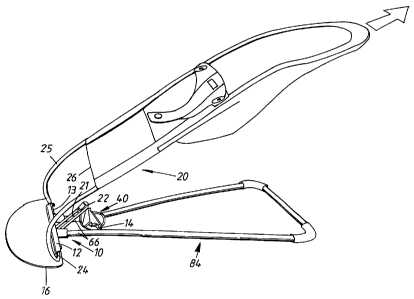
A bouncing cradle comprising a base frame (10), a backrest (20), a first pivot mounting (12) arranged for the backrest (20) and carried by the base frame (10), an arm (22) fixedly connected to the backrest (20) and situated under the backrest (20) as well as at a distance from the first pivot mounting (12), the arm being, via a second pivot mounting (22, 23), connected to an adjustment fitting (40), the adjustment fitting (40) having at least two recesses (51, 52) that are situated at different distances from the second pivot mounting (22, 23) and that can receive a bar (14) carried by the base frame (10) and situated at a distance from the first pivot mounting, for setting different angles of inclination of the backrest (20) in relation to the base frame (10), the bar (14), the arm (22) and the first and the second mounting (12, 22) being axially parallel and the base frame (10) being intended to stand on a substantially horizontal underlay. The adjustment fitting (40) has a through elongate opening (60) having a side (61), which is turned obliquely downward and facing the first pivot mounting and in which the recesses (51, 52, 53) are situated. Each recess (51-53) has a bottom part (62) that supportingly receives the bar (14), and a mouth portion (63) that, obliquely downward and toward the first pivot mounting, mouths into the opening (60).


French Abstract

On décrit un berceau basculant qui comprend: un cadre de base (10), un dossier (20) une première fixation oscillante (12) destinée au dossier (20) et reposant sur le cadre de base (10), un bras (22) fixé au dossier (20) et situé sous ce dernier (20) et à distance de la fixation oscillante (12), ledit bras étant relié par une seconde fixation oscillante (22, 23) à un accessoire de réglage (40). L'accessoire de réglage (40) présente au moins deux évidements (51, 52) situés à des distances différentes de la seconde fixation oscillante (22, 23) et pouvant loger une tige (14) reçue par le cadre de base (10) et situé à une distance de la fixation oscillante pour régler différents angles d'inclinaison du dossier (20) relativement au cadre de base (10). La tige (14), le bras (22) et la première et la seconde fixation oscillante (12, 22) sont axialement parallèles, le cadre de base (10) étant conçu pour reposer sur une assise sensiblement horizontale. L'accessoire de réglage (40) comporte une ouverture allongée débouchante (60) présentant un côté (61) incliné vers le bas et faisant face à la première fixation oscillante, et dans lequel sont situés les évidements (51, 52, 53). Chaque évidement (51, 53) comprend une partie de fond (62) qui reçoit la tige (14) et lui sert de support, et une bouche (63) donnant sur l'ouverture (60) par inclinaison vers le bas et en direction de la première fixation oscillante.

Claims

Note: Claims are shown in the official language in which they were submitted.


10
WE CLAIM:
1. A bouncing cradle comprising a base frame, a backrest, a first pivot
mounting carried by the backrest and carried by the base frame, an arm
fixedly connected to the backrest and situated under the backrest as well as
at a distance from the first pivot mounting, the arm being, via a second pivot

mounting, connected to an adjustment fitting, the adjustment fitting having
at least two recesses that are situated at different distances from the second

pivot mounting and that can receive a bar carried by the base frame, the bar
being situated at a distance from the first pivot mounting, for setting
different angles of inclination of the backrest in relation to the base frame,

the bar, the arm and the first and the second pivot mounting being axially
parallel and the base frame being intended to stand on a substantially
horizontal underlay, characterized in that the adjustment fitting has a
through elongate opening having a side, which is turned obliquely downward
and facing the first pivot mounting and in which the recesses are situated,
that each recess has a bottom part that supportingly receives the bar, and a
mouth portion that, obliquely downward and toward the first pivot mounting,
mouths into the opening.
2. Bouncing cradle according to claim 1, characterized in that a wall of the
mouth portion of each recess that is facing the first pivot mounting forms an
angle of less than 90 to a line through the axes of the bar and of the second

pivot mounting, and that a bottom portion at an opposite wall of the recess is

undercut.
3. Bouncing cradle according to claim 1, characterized in that the opening is
delimited by a locking arm that is turnably mounted on the adjustment fitting
and spring biased against an end position in which it delimits the opening
toward the second pivot mounting, and that the locking arm is possible to

11
turn away against the action of the spring bias, whereby the opening is
brought in communication with an additional elongate opening that extends
up to an area of the second pivot mounting.
4. Bouncing cradle according to claim 3, characterized in that the locking arm
is
formed in order to, on the side thereof facing the opening, guide a shank of
the bar from the opening into an adjacent recess.
5. Bouncing cradle according to claim 3, characterized in that the locking arm
is
arranged to, upon turning away, be turned into an area of the opening, and
then blocks an adjacent recess so that the bar has to be situated in some one
of the other recesses in order to allow the locking arm to be turned away and
allow the bar to be moved into said additional opening.

Description

Note: Descriptions are shown in the official language in which they were submitted.


CA 02654691 2008-12-08
WO 2008/004959 PCT/SE2007/000676
1
A bouncing cradle

The invention relates to a bouncing cradle, or bouncy
chair, of the kind that is seen in the preamble of the
appended claim 1.

Thus, the invention relates to a bouncing cradle (chil-
dren's reclining chair) of the kind that comprises a base
frame, which is intended to rest on a plane underlay, a
backrest, for a first pivot mounting arranged for the
backrest and carried by the base frame, an arm fixedly
connected to the backrest and situated under the backrest
as well as at a distance from the first pivot mounting,
the arm being, via a second pivot mounting, connected to
an adjustment fitting 40, which has at least two recesses
that are situated at different distances from the second
pivot mounting and that can receive a bar carried by the
base frame, for setting different angles of inclination of
the backrest in relation to the base frame, the bar, the
arm and the pivot mountings being axially parallel. By
bringing different recesses into engagement with the bar,
it is possible to set a number of preselected inclination
positions of the backrest, for instance inclination posi-
tions that are suitable for a number of different things
to do for the child, such as play, rest, sleep.

An object of the invention is to provide a bouncing cra-
dle, which easily and with high safety can be readjusted
between said inclination positions.

An additional object is to provide a bouncing cradle that
also upon lifting in the backrest retains the set inclina-
tion position of the backrest in relation to the base

f rame .


CA 02654691 2008-12-08
WO 2008/004959 PCT/SE2007/000676
2

An additional object is to provide a construction that
affords folding of the backrest substantially parallel to
the base frame into a transportation position, as well as
detachable securing of the backrest and the base frame in
the transportation position.

An additional object is to provide a bouncing cradle that,
after conversion from the transportation position into the
using state, automatically, upon load, assumes a stable
inclination position of the backrest.

An additional object is to provide a bouncing cradle that
has a locking device, which upon actuation allows the con-
version of the bouncing cradle between the transportation
state and the using state.

Further other objects and advantages of the invention are
defined directly or indirectly in the following the
description.

The objects are entirely or partly attained by the inven-
tion.

The invention is defined in the appended independent claim
l.

Embodiments of the invention are defined in the appended
dependent claims.

In the following, an embodiment of the invention will be
described, reference being made to the appended drawing.


CA 02654691 2008-12-08
WO 2008/004959 PCT/SE2007/000676
3
Figure 1 schematically and in perspective shows a bouncing
cradle.

Figure 2 shows an enlarged depiction of a detail of the
bouncing cradle according to Figure 1, comprising an
inclination adjustment fitting.

Figures 3, 4, 5 show in depictions corresponding to Figure
2, different rotary positions of the adjustment fitting
upon transition from an inclination-determining using
position, into a transportation position of the bouncing
cradle.

Figure 6 shows a broken-away side view of the adjustment
fitting.

Figure 7 shows a planar view of a support plate belonging
to the base frame.

Figure 8 shows a view taken along the line VIII-VIII in
Figure 7.

Figure 9 shows a section taken along the line A-A in Fig-
ure 8.

Figure 1 illustrates a bouncing cradle comprising a back-
rest 20, which is formed of a generally U-shaped frame
part 25 on which a cloth bag is to be pulled on so as to
form a reclining support for an infant. (In Figure 1, the
bag is shown not fully pulled on, for reasons of lucidity.
On the cloth bag, a pair of cloth trousers is shown, into
which the child should be put down).


CA 02654691 2008-12-08
WO 2008/004959 PCT/SE2007/000676
4
The backrest frame 25 is supplemented by two straight and
axially aligned frame pieces 24 and a generally U-shaped
yoke integratedly attached between the same.

The frame pieces 24 are received in a pivot mounting 12
along a straight edge 13 of a support plate 16 belonging
to a base frame 10, which is intended to stably rest on a
horizontal underlay. An essentially flat yoke of a gener-
ally triangular nature has the free ends 66 thereof paral-
lel to and attached in the support plate. At a distance
from the ends 66, the yoke is widened so as to form two
support points, which are laterally spaced-apart in rela-
tion to the backrest 20. Said two support points may be
established by friction material applied on the underside
of the yoke in the corner areas of the yoke between the
web and the branches. The support plate 16 may, on the
underside along the circumference border thereof, be pro-
vided with a strand of friction material, for instance
rubber, as anti-skid protection.
It can be seen that a bar 14 extends between the yoke ends
66, the bar 16 being received in the respective hole in
the yoke end parts.

An adjustment fitting 40 has a pivot mounting 23 for the
web part 22 of the U-shaped part of the backrest frame.
From Figures 2 and 6, it can be understood that the bar 14
and the arm 22 are approximately at the same distance from
the pivot mounting 12, and that the adjustment fitting 40
has an elongate opening 60 having a side 60, which is
turned obliquely downward and facing the first pivot
mounting 12 and in which recesses 51, 52, 53 are situated.
Each recess has a bottom part 62 that supports the bar 14,


CA 02654691 2008-12-08
WO 2008/004959 PCT/SE2007/000676
and a mouth portion 63 that, obliquely downward and toward
the first pivot mounting, mouths in the opening 60. The
bar 14, the arm 22 and the pivot mountings 12, 23 are axi-
ally parallel.

5
The elongate opening 60 is delimited toward the upper end
thereof by a locking arm 70, which is pivotally mounted
around a spindle 71 in the vicinity of the pivot mounting
23, and is biased by a spring 72 toward the end position
shown.

By the inclinations accounted for, the bar 14 can always,
from the opening 60, slide on surfaces inclined to the
vertical into the bottom portion 62 of a recess, when the
backrest is loaded vertically. From Figure 6, it is possi-
ble to further see that the mouth portion 63 of the recess
has a width that is greater than the diameter of the bar
14, and that the bottom portion 62 of the recess at the
upper part thereof is undercut in order to stably receive
the bar 14 and prevent the bar 14 from sliding out of the
recess, when the backrest is vertically loaded, independ-
ently of which recess the bar 14 is received in.

From Figure 6, it can be seen that the locking arm 70 in
the shown end position thereof, by the side thereof facing
the opening 60, intersects the upper mouth wall of the
recess 51 and forms a guide surface for the introduction
of the bar 14 from the opening 60 into the mouth part of
the recess 51.

By means of a bias spring 73, the locking arm 70 is biased
against a stopper 74. The arm 70 can be turned manually
against the action of the spring 73 and, in doing so,
brings the opening 60 in communication with an additional


CA 02654691 2008-12-08
WO 2008/004959 PCT/SE2007/000676
6
elongate opening 80 in the fitting 40, the opening 80
extending up to the area of the pivot mounting 23.
Furthermore, it can be seen that on the outside thereof,
the fitting 40 has a gripping ear 90, which facilitates
manual turning of the fitting 40 around the mounting 22,
23. Figure 3 illustrates that the bar 14 is in the recess
52, and that it is desirable to convert the bouncing cra-
dle into a transportation position in which the backrest
is generally parallel and next to the base frame 10. In
doing so, the locking arm 70 is turned back against the
action of the spring 73 in the direction of the arrow
indicated in Figure 3, so that the fitting 40 can be
turned in such a manner that the bar 14 leaves the recess
52 and runs along the opening 60 and inward toward the
opening 80, such as is indicated by the arrow in Figure 4.
Upon continued turning of the fitting 40 around the mount-
ing 22, 23, the turning motion of the fitting 40 is con-
tinued according to Figure 4 until the fitting 40 assumes
the position shown in Figure 5, in which the pivot mount-
ing 23 is situated in the vicinity of the bar 14 (not
shown), the bouncing cradle having assumed the transporta-
tion position. In the transportation position, the U-yoke
part 37 extends at an angle under the plane of the base
frame 10, and the web 22 thereof is situated on a level
under the bar 14.

Figure 7 illustrates that the support plate 16 has a pair
of integrated sleeves 85, which receive the ends 66 of the
yoke 84. Furthermore, it is seen that the sleeves 85 as
well as the yoke ends 66 have vertically aligned through
holes, and that a bolt joint extends therethrough. The
bolt joint is shown to have a nut at the top and has a
screw head at the bottom. The straight front edge 13 of


CA 02654691 2008-12-08
WO 2008/004959 PCT/SE2007/000676
7
the support plate has a groove that receives the straight
frame pieces 24. The U-yoke part 37, the bottom web of
which forms the arm 22, is carried by the frame pieces 24
via the pair of arms 21.

The screw heads 86 of the bolt joints confine the straight
frame pieces 24 in the grooves in the support plate 16.
The integrated sleeves 85 afford a stable high-strength
connection to the support plate 16, and afford, by means
of the bolt joints, a simple connection of the yoke 84 to
the support plate 16. From Figure 7, it is possible to
further see that the support plate has integrated buttons
28 that, in addition to confining the frame pieces 24,
also afford anchorage of the lower border part of the bag
that is threaded onto the frame part 25 for the formation
of the backrest 20. In that connection, the front part of
the bag has buttonhole openings in alignment with the but-
tons 28, whereby a stable anchorage of the bag in the
stretched state is attained.
From Figures 7 and 8, it can be seen that the support
plate 16 has a projecting U-girder 110, which is situated
between the sleeves 85 and is integrated with the injec-
tion-moulded support plate 16. The bottom web 111 of the
girder 110 is situated at the topside of the support
plate, and the branches 112 thereof extend downward there-
from. The distance between the outsides of the branches is
somewhat smaller than the free distance between the branch
arms 21 of the U-yoke 37. In this way, the U-yoke 37 is
centred and thereby the backrest 20 in relation to the
base frame, when the U-yoke is turned down over the U-
girder. By the fact that the free branch ends of the
girder 110 have generally wedge-shaped protuberances 114
at least at the free end of the girder, an interference


CA 02654691 2008-12-08
WO 2008/004959 PCT/SE2007/000676
8
between said protuberances 114 and the arms 21 is
afforded, and the arms 21 are locked detachably under said
protuberances 114 when the arms 21 have passed past them.
The branches 112 are elastically resilient and also allow,
thanks to a wedge 113, a turning back of the U-yoke piece
37 past the arms 21, so that the branches are driven
toward each other upon the turning back of the U-yoke 37
away from the transportation position. That is, the branch
ends having the wedges 113, 114 form a detachable catch
for the retention of the backrest next to the base frame
in the transportation position.

Finally, from Figure 6, it can be understood that the
recesses 51, 52, 53 allow free passage of the bar 14 to
and from the bottom portion 62, with the exception of a
small dog 64 possibly being arranged at the transition
between the mouth portion 63 and bottom part 62 of the
recess in the upper wall of the recess. Said dog 64 forms,
together with the opposite recess wall, a waist that is
somewhat smaller than the diameter of the bar 14. Thanks
to an elastic resiliency of the opposite walls of the
recess in the vicinity of said dog 64, a snap-locking
function is afforded that blocks the bar 14 from uninten-
tionally leaving the bottom part 62 of the recess. The
undercut of the upper side wall of the recess in the bot-
tom part serves to guarantee that the bar 14 cannot leave
the recess upon loading of the backrest in the direction
of the base frame.

The upper side wall of the recess leans at an angle (3 <
90 to the line 29 between the centres of the bar 14 and
of the arm part 22. The lower side wall of the recess
leans, as is seen from Figure 6, at an angle a> 90 to
the line 29.


CA 02654691 2008-12-08
WO 2008/004959 PCT/SE2007/000676
9

By the fact that the upper wall of the elongate opening 60
has a substantial inclination to the horizontal, independ-
ently of the position of the bar 14 along the opening 60,
the bar 14 will be able to slide along the upper smooth
opening wall, when the backrest is loaded. When the bar 14
then is introduced into a recess 52, 53, the bar will 14
easily slide along the upper smooth mouth wall of the
recess, which also has a substantial inclination to the
horizontal, and passes into the bottom part 62 of the
recess. Hence, the bar 14 automatically makes for one of
the recesses 51-53 upon loading of the backrest.

From Figures 7-9, it is possible to further see that each
sleeve 85 has a nut socket 87, which rotationally secures
a lock nut that receives a through screw, the head of
which radially projects from the diametrically opposed
side of the sleeve and screens off the groove in order to
locally restrain a straight frame piece 24 therein. At the
other end of the frame piece, the same is restrained in
the groove by a respective dog 64. The screw is suitably
of the Allen-type and the nut 87 is suitably a lock nut
having friction inserts.


Representative Drawing
A single figure which represents the drawing illustrating the invention.
Administrative Status

For a clearer understanding of the status of the application/patent presented on this page, the site Disclaimer , as well as the definitions for Patent , Administrative Status , Maintenance Fee  and Payment History  should be consulted.

Administrative Status

Title Date
Forecasted Issue Date 2014-05-20
(86) PCT Filing Date 2007-07-06
(87) PCT Publication Date 2008-01-10
(85) National Entry 2008-12-08
Examination Requested 2012-06-22
(45) Issued 2014-05-20

Abandonment History

There is no abandonment history.

Maintenance Fee

Last Payment of $624.00 was received on 2024-06-26


 Upcoming maintenance fee amounts

Description Date Amount
Next Payment if standard fee 2025-07-07 $624.00 if received in 2024
$651.46 if received in 2025
Next Payment if small entity fee 2025-07-07 $253.00 if received in 2024
$264.13 if received in 2025

Note : If the full payment has not been received on or before the date indicated, a further fee may be required which may be one of the following

  • the reinstatement fee;
  • the late payment fee; or
  • additional fee to reverse deemed expiry.

Patent fees are adjusted on the 1st of January every year. The amounts above are the current amounts if received by December 31 of the current year.
Please refer to the CIPO Patent Fees web page to see all current fee amounts.

Payment History

Fee Type Anniversary Year Due Date Amount Paid Paid Date
Application Fee $400.00 2008-12-08
Maintenance Fee - Application - New Act 2 2009-07-06 $100.00 2008-12-08
Registration of a document - section 124 $100.00 2010-02-26
Maintenance Fee - Application - New Act 3 2010-07-06 $100.00 2010-06-15
Maintenance Fee - Application - New Act 4 2011-07-06 $100.00 2011-06-07
Maintenance Fee - Application - New Act 5 2012-07-06 $200.00 2012-06-08
Request for Examination $800.00 2012-06-22
Maintenance Fee - Application - New Act 6 2013-07-08 $200.00 2013-06-10
Final Fee $300.00 2014-03-06
Maintenance Fee - Patent - New Act 7 2014-07-07 $200.00 2014-06-10
Maintenance Fee - Patent - New Act 8 2015-07-06 $200.00 2015-06-10
Maintenance Fee - Patent - New Act 9 2016-07-06 $200.00 2016-06-23
Maintenance Fee - Patent - New Act 10 2017-07-06 $250.00 2017-06-19
Maintenance Fee - Patent - New Act 11 2018-07-06 $250.00 2018-06-18
Maintenance Fee - Patent - New Act 12 2019-07-08 $250.00 2019-06-26
Maintenance Fee - Patent - New Act 13 2020-07-06 $250.00 2020-06-24
Maintenance Fee - Patent - New Act 14 2021-07-06 $255.00 2021-06-29
Maintenance Fee - Patent - New Act 15 2022-07-06 $458.08 2022-06-29
Maintenance Fee - Patent - New Act 16 2023-07-06 $473.65 2023-06-22
Maintenance Fee - Patent - New Act 17 2024-07-08 $624.00 2024-06-26
Owners on Record

Note: Records showing the ownership history in alphabetical order.

Current Owners on Record
BABYBJORN AB
Past Owners on Record
BABY BJOERN AB
BERGKVIST, HAKAN
Past Owners that do not appear in the "Owners on Record" listing will appear in other documentation within the application.
Documents

To view selected files, please enter reCAPTCHA code :


To view images, click a link in the Document Description column. To download the documents, select one or more checkboxes in the first column and then click the "Download Selected in PDF format (Zip Archive)" or the "Download Selected as Single PDF" button.

List of published and non-published patent-specific documents on the CPD .

If you have any difficulty accessing content, you can call the Client Service Centre at 1-866-997-1936 or send them an e-mail at CIPO Client Service Centre.


Document
Description 
Date
(yyyy-mm-dd) 
Number of pages   Size of Image (KB) 
Representative Drawing 2009-04-02 1 11
Maintenance Fee Payment 2022-06-29 1 33
Abstract 2008-12-08 1 74
Claims 2008-12-08 2 81
Drawings 2008-12-08 5 94
Description 2008-12-08 9 370
Cover Page 2009-04-17 2 57
Claims 2012-06-22 2 61
Cover Page 2014-04-25 2 57
Assignment 2010-02-26 5 189
PCT 2008-12-08 4 158
Assignment 2008-12-08 5 117
Fees 2010-06-15 1 34
Prosecution-Amendment 2012-06-22 4 126
Correspondence 2012-06-22 2 65
Correspondence 2014-03-06 1 50