Note: Descriptions are shown in the official language in which they were submitted.
CA 02654750 2008-12-08
WO 2007/146148 PCT/US2007/013544
1
STRETCHABLE OUTER COVER FOR AN ABSORBENT ARTICLE AND PROCESS FOR
MAKING THE SAME
FIELD OF THE INVENTION
The invention provides at least one embodiment that generally relates to
absorbent
articles, and stretchable outer covers ("SOCs") used therewith. More
specifically, an
embodiment of the invention relates to a stretchable outer cover having
underwear-like, low-
force, recoverable stretch. At least one embodiment of the invention also
relates to an
elastomeric film comprising an elastomeric core layer and an elastomeric skin
layer, wherein the
elastomeric skin layer has less tack than the elastomeric core layer.
BACKGROUND OF THE INVENTION
Absorbent articles such as conventional taped diapers, pull-on diapers,
training pants,
incontinence briefs, and the like, offer the benefit of receiving and
containing urine and/or other
bodily exudates. Such absorbent articles can include a chassis that defines a
waist opening and a
pair of leg openings. A pair of barrier leg cuffs can extend from the chassis
toward the wearer
adjacent the leg openings, thereby forming a seal with the wearer's body to
improve
containment of liquids and other body exudates. Conventional chassis typically
include an
absorbent core that is disposed between a topsheet and a garment-facing outer
cover (sometimes
referred to as a backsheet).
The outer cover can include a stretchable waistband at one or both of its ends
(e.g.,
proximal opposing laterally extending edges), stretchable leg bands
surrounding the leg
openings, and stretchable side panels, which additional components can be
integral or separate
discrete elements attached directly or indirectly to the outer cover. The
remainder of the outer
cover typically includes a non-stretchable nonwoven-breathable film laminate.
Undesirably,
however, these diapers sometimes do not conform well to the wearer's body in
response to body
movements (e.g. sitting, standing, and walking), due to the relative anatomic
dimensional
changes (which can, in some instances, be up to 50%) in the buttocks region
caused by these
movements. This conformity problem is further exacerbated because one diaper
typically must
fit many wearers of various shapes and sizes in a single product size.
Many of the elastomeric films used in absorbent articles have a relatively
high tack,
which may increase the difficulty of winding these films on rolls. Attempts to
minimize the tack
include laminating the tacky portion of the film to a nonwoven or include a
non-tacky skin on
CA 02654750 2008-12-08
WO 2007/146148 PCT/US2007/013544
2
the film prior to winding up on a roll. Typically, polyolefin skins are used.
One disadvantage of
using a skin is that it may negatively impact the elastomeric properties of
the film. Activating
the elastomeric film either by itself or after laminating it to one or more
layers of nonwovens
may generate pin holes due to the relatively high depth of engagement ("DOE")
needed to
suitably break up the skin layer. Another disadvantage is that the non-elastic
skin layer may add
cost without providing any additional stretch.
Many caregivers and wearers prefer the look and feel of cotton underwear not
provided
by conventional diapers. For instance, cotton underwear includes elastic waist
and leg bands
that encircle the waist and leg regions of the wearer and provide the primary
forces that keep the
underwear on the wearer's body. Furthermore, the cotton outer cover (except in
the waist and
leg bands) can be stretched along the width and length directions in response
to a relatively low
force to accommodate the anatomic dimensional differences related to movement
and different
wearer positions. The stretched portion returns back to substantially its
original dimension once
the applied force is removed. In other words, the cotton outer cover of the
underwear exhibits
low-force, recoverable biaxial stretch that provides a conforming fit to a
wider array of wearer
sizes than conventional diapers.
Biaxially activation of the outer cover of an absorbent article may provide
the low-force,
recoverable stretch underwear-like material desired by some consumers, but the
process for
making such an outer cover may be difficult. Activating a typical outer cover
in more than one
direction may result in mechanical failure of the outer cover. These
mechanical failings may
manifest as pinholes, wrinkles or other functional or aesthetically
undesirable features. In
addition, providing a breathable outer cover for increased wearer comfort may
also increase the
difficulty of the manufacturing process due to the inclusion of apertures,
micropores, and/or
other discontinuities in the outer cover. Such opening may increase the
possibility of
mechanical failure of the outer cover materials during an activation process.
Accordingly, it would be desirable to provide an outer cover having an
elastomeric skin
layer with less tack than a core layer. It would further be desirable to
provide a low-force,
recoverable-stretch outer cover having the texture and aesthetics of cotton
underwear. It would
further be desirable to provide a process for manufacturing a breathable outer
cover having the
texture and aesthetics of cotton underwear.
SUMMARY OF THE INVENTION
In order to provide a solution to the problems above at least one embodiment
of the
CA 02654750 2008-12-08
WO 2007/146148 PCT/US2007/013544
3
invention provides a stretchable outer cover for an absorbent article. The
stretchable outer cover
includes a multilayered elastomeric film layer. The multilayered elastomeric
film layer includes
at least one skin layer and at least one elastomeric core layer. The skin
layer is_ elastomeric or
plastoelastic. The elastomeric core layer includes a first elastomeric
polypropylene. The skin
layer is less tacky than the core layer.
BRIEF DESCRIPTION OF THE DRAWINGS
FIG. I is cross section view of an absorbent article comprising an outer cover
according
to an embodiment of the invention.
FIG. 2 is cross section view of an outer cover according to an embodiment of
the
invention.
FIG. 3 is a scanning electron micrograph of a nonwoven substrate for use with
an outer
cover in an embodiment of the invention.
FIG. 4 is a graphical representation of the data listed in Table 9.
FIG. 5 is a graphical representation of the data listed in Table 10.
DETAILED DESCRIPTION OF THE INVENTION
DEFINITIONS
As used herein, the following terms shall have the meaning specified
thereafter:
The term "disposable," as used herein in reference to absorbent articles,
means that the
absorbent articles are generally not intended to be laundered or otherwise
restored or reused as
absorbent articles (i.e., they are intended to be discarded after a single use
and may be recycled,
composted or otherwise discarded in an environmentally compatible manner).
The term "absorbent article" as used herein refers to devices which absorb and
contain
body exudates and, more specifically, refers to devices which are placed
against or in proximity
to the body of the wearer to absorb and contain the various exudates
discharged from the body.
Exemplary absorbent articles include diapers, training pants, pull-on pant-
type diapers (i.e., a
diaper having a pre-formed waist opening and leg openings such as illustrated
in U.S. Patent No.
6,120,487), refastenable diapers or pant-type diapers, incontinence briefs and
undergarments,
diaper holders and liners, feminine hygiene garments such as panty liners,
absorbent inserts, and
the like.
CA 02654750 2008-12-08
WO 2007/146148 PCT/US2007/013544
4
The term "machine direction" (also "MD" or "length direction") as applied to a
film or
nonwoven material, refers to the direction that is parallel to the direction
of travel of the film or
nonwoven as it is processed in the forming apparatus. The "cross machine
direction" or "cross
direction" (also "CD" or "width direction") refers to the direction
perpendicular to the machine
direction and in the plane generally defined by the film or nonwoven material.
The term "longitudinal" as used herein refers to a direction running
substantially
perpendicular from a waist edge to an opposing waist edge of the article and
generally parallel to
the maximum linear dimension of the article. Directions within 45 degrees of
the longitudinal
direction are considered to be "longitudinal."
The term "lateral" as used herein refers to a direction running from a
longitudinal edge to
an opposing longitudinal edge of the article and generally at a right angle to
the longitudinal
direction. Directions within 45 degrees of the lateral direction are
considered to be "lateral."
The term "disposed" as used herein refers to an element being positioned in a
particular
place with regard to another element. When one group of fibers is disposed on
a second group
of fibers, the first and second groups of fibers generally form a layered,
laminate structure in
which at least some fibers from the first and second groups are in contact
with each other. In
some embodiments, individual fibers from the first and/or second group at the
interface between
the two groups can be dispersed among the fibers of the adjacent group,
thereby forming an at
least partially intermingled, entangled fibrous region between the two groups.
When a
polymeric layer (for example a film) is disposed on a surface (for example a
group or layer of
fibers), the polymeric layer can be laminated to or printed on the surface.
"Joined" refers to configurations whereby an element is directly secured to
another
element by affixing the element directly to the other element and to
configurations whereby an
element is indirectly secured to another element by affixing the element to
intermediate
member(s) which in turn are affixed to the other element.
As used herein, the term "stretchable" refers to materials which can stretch
at least 5% on
the upcurve of the Hysteresis Test at a load of400 gf/cm. The term "non-
stretchable" refers to
materials which cannot stretch to at least 5% on the upcurve of the Hysteresis
Test at a load of
400 gf/cm.
The terms "elastic" and "elastomeric" as used herein are synonymous and refer
to any
material that upon application of a biasing force, can stretch to an elongated
length of at least
110% or even to 125% of its relaxed, original length (i.e. can stretch to 10%
or even 25% more
than its original length), without rupture or breakage. Further, upon release
of the applied force,
CA 02654750 2008-12-08
WO 2007/146148 PCT/US2007/013544
the material may recover at least 40%, at least 60%, or even at least 80% of
its elongation. For
example, a material that has an initial length of 100 mm can extend at least
to 110 mrn, and upon
removal of the force would retract to a length of 106 mm (i.e., exhibiting a
40% recovery). The
term "inelastic" refers herein to a material that cannot stretch to 10% more
than its original
length without rupture or breakage.
The terms "extensible" and "plastic" as used herein are synonymous and refer
to any
material that upon application of a biasing force, can stretch to an elongated
length of at least
110% or even 125% of its relaxed, original length (i.e., can stretch to 10% or
even 25% more
than its original length), without rupture or breakage. Further, upon release
of the applied force,
the material shows little recovery, for example less than 40%, less than 20%,
or even less than
10% of its elongation.
The terms "plastoelastic" and "elastoplastic" as used herein are synonymous
and refer to
any material that has the ability to stretch in a substantially plastic manner
during an initial strain
cycle (i.e., applying a tensile force to induce strain in the material, then
removing the force
allowing the material to relax), yet which exhibits substantially elastic
behavior and recovery
during subsequent strain cycles. Plastoelastic materials contain at least one
plastic component
and at least one elastic component, which components can be in the form of
polymeric fibers,
polymeric layers, and/or polymeric mixtures (including, for example, bi-
component fibers and
polymeric blends including the plastic and elastic components). Suitable
plastoelastic materials
and properties are described in U.S. 2005/0215963 and U.S. 2005/0215964.
As used herein, the term "activated" refers to a material which has been
mechanically
deformed so as to impart elastic extensibility to at least a portion the
material, such as, for
example by incremental stretching.
"Nanofibers" are sub-micron diameter fibers formed according to the process
outlined in
U.S. 2005/0070866 and U.S. 2006/0014460. Nanofibers generally have diameters
of 0.1 m to
1 m, although larger diameters are possible. The number-average nanofiber
diameter is
generally in a range of 0.1 m to 1 m, for example 0.5 m.
As used herein, the term "skin layer" generally refers to one or more layers
in a
multilayer film coextruded with at least one other layer (typically a core
layer) such that each of
the one or more skin layers represent less than 25%; or even less than 10% of
the total film
thickness. It is to be understood that when multiple skin layers are present
the thickness of each
skin layer need not necessarily be the same.
CA 02654750 2008-12-08
WO 2007/146148 PCT/US2007/013544
6
As used herein, the term "core layer" generally refers to one or more layers
in a
multilayer film coextruded with at least one other layer (typically a skin
layer) such that each of
the one or more core layers represent more than 50%; or even more than 75% of
the total film
thickness. It is to be understood that when multiple core layers are present
the thickness of each
core layer need not necessarily be the same.
As used herein, the term "underwear-like" generally refers to a substrate that
exhibits
low-force, recoverable stretch, which it similar to typical the
characteristics exhibited by the
cotton fabric portion of cotton underwear (this excludes the waist band and
leg bands portions).
For example, a substrate such as an outer cover for an absorbent article, that
exhibits a load at
15% strain of less than 40 g/cm is considered underwear-like.
As used herein, "extrusion-lamination" generally means a process where a
polymer is
extruded onto at least one other nonwoven, and while still in a partially
molten state, bonds to
one side of the nonwoven, or by depositing onto an extruded molten polymer, a
nonwoven.
General Description of the Embodiments
The stretchable outer covers ("SOCs") according to at least one embodiment of
the
invention may include at least one elastic material and at least one plastic
material. The
stretchable outer cover ("SOC") may include a layer of polymeric material and
a nonwoven
layer disposed on the polymeric material. The nonwoven material and the
polymeric layer can
be formed (independently) from a plastoelastic material, an elastic material,
or a plastic material.
Although the SOC may have at least one plastic material and at least one
elastic material, the
two components can be included in the SOC in the form of a single
plastoelastic material.
In certain embodiments of the invention, the SOC may include a polymeric layer
in the
form of a polymeric film laminated to the nonwoven material. These embodiments
may have
three additional aspects in which: (1) a layer of plastoelastic nonwoven
material is laminated to a
plastic polymeric film, (2) a layer of plastoelastic nonwoven material is
laminated to a
plastoelastic polymeric film, and (3) a layer of plastic nonwoven material is
laminated to a
plastoelastic polymeric film. When both the nonwoven material and the
polymeric film are
formed from a plastoelastic material, they can be formed from either the same
or different
plastoelastic materials. In certain embodiments, the SOC may include a layer
of nonwoven
material, such as, for example a layer of plastic fibers, onto which an
elastomeric layer is printed
or laminated in the form of a pattern or film.
The SOC of at least one embodiment of the invention has low-force, recoverable
stretch,
similar to the fabric of cotton underwear. In some embodiments, the outer
cover may have a low
CA 02654750 2008-12-08
WO 2007/146148 PCT/US2007/013544
7
force at a specific elongation. Since the outer cover can have different
stretch properties in
different directions, stretch properties may be measured in the longitudinal
direction (machine
direction) and in the lateral direction (cross machine direction). In some
embodiments, at 15%
strain, the outer cover may have a first cycle load less than 40 g/cm; 30
g/cm; 20 g/cm; or even
less than 15 g/cm. In some embodiments, at 50% strain, the outer cover may
have a first cycle
load less than 100 g/cm; 75 g/cm; 40 g/cm or even less than 30 g/cm.
Additionally, in some
embodiments, the outer cover may also have a percentage set that is less than
40%; 30%; 20% or
even less than 10%. It is believed that an outer cover with such properties
may be more
underwear-like.
In certain embodiments, an outer cover according to at least one embodiment of
the
invention may comprise an elastomeric film that is laminated to at least one
non-elastic
nonwoven. Each layer of nonwoven may have a basis weight of less than 50 g/mZ;
between 10
and 30 g/m2; or even between 10 and 20 g/m2. The basis weight of the
elastomeric film may be
less than 40 g/m2; 30 g/m2; 25 g/m2; or even less than 15 g/m2.
Since, the elastomer included in an absorbent article may be one of the more
expensive
components of the diaper, and since the area of the outer cover, hence
elastomer usage, may be
large for an all-over stretch outer cover, it may be desirable to be able to
commercially make an
outer cover with a low basis weight elastomer that is relatively inexpensive.
Elastomeric
polypropylenes may be attractive candidates, e.g. VISTAMAXX from Exxon-Mobil,
as they are
typically less expensive than conventional elastomers such as styrenic block
copolymers. In
addition, it may be easier to extrude these elastomeric polypropylenes at low
basis weights (e.g.,
10-40 g/m2) commercially compared to the styrenic block polymers, due to their
higher melt
strengths. Finally, since many other absorbent article components are often
made of
polypropylene, mechanical bonding with the elastomeric polypropylenes may be
easier.
FIG. I shows a schematic view of an example of an absorbent article 101 that
includes
an outer cover 124 according to at least one embodiment of the invention. In
this example, the
outer cover 124 is a bilaminate formed from an elastomeric film 165 and a
nonwoven 162. The
outer cover 124 has a body facing side 171 and a garment facing side 170. In
addition to an
outer cover 124, the absorbent article may also include a topsheet 122 joined
to the absorbent
core 26 or any other component by any means commonly known in the art, such
as, for example
adhesive. The absorbent core 26 may be joined to the outer cover 124. The
outer cover 124
shown in FIG. 1 may include an elastomeric film 165 comprising a skin layer
163 and a core
layer 164. The skin layer 163 may be joined to the core layer 164 in a face to
face configuration
CA 02654750 2008-12-08
WO 2007/146148 PCT/US2007/013544
8
to form a laminate. In a film-nonwoven bilaminate, the skin layer 163 is
generally disposed on
the body facing side 171 of the outer cover 124. While only a single skin
layer 163 and a single
core layer 164 is shown in FIG. 1, it, is to be understood that the outer
cover 124 may include
additional skin and/or core layers, as desired. Optionally, the outer cover
124 may also include a
second nonwoven material 162 as shown in FIG. 2. In FIG. 2, the elastomeric
film 165 has two
skin layers 163 and two nonwoven layers 162. Such a structure may be formed
when the steps
of film formation and lamination to nonwovens are done at different times
and/or locations. The
nonwoven 162 may be joined to the elastomeric film 165 by any means commonly
known in the
art
Like underwear, the absorbent article may also include elastic waist and leg
bands in
addition to the Stretchable Outer Cover (SOC). These bands ideally would cover
substantially
the entire circumference around the waist and legs. These waist and leg bands
help decrease
diaper sag, especially since the SOC offers only little return force. These
waist and leg bands
would be laminates of an elastic material and at least one nonwoven, wherein
the elastic is
prestretched prior to bonding it to the nonwoven (i.e. Stretch Bonded
Laminate). The elastic
material could be in the form of strands or film or a nonwoven. Any bonding
technique known
in the industry can be used to bond the elastic material to the nonwoven. Some
examples are
adhesive bonding, ultrasonic bonding, thermal point bonding, mechanical
bonding with pressure
and/or heat, and the like.
The elastic waist and leg bands are 5 to 40 mm wide. One example is a
trilaminate
comprising Spandex strands, having a decitex of 400 to 1500, and laminated to
two layers of
nonwovens. These strands, which run along the machine direction of the web,
are prestretched
to 100-300% prior to laminating to the nonwoven. The waist and leg bands are
next
prestretched prior to bonding them to the SOC.
Polymeric Materials
The plastoelastic materials according to at least one embodiment of the
invention,
whether included in a nonwoven fibrous layer or a polymeric film layer, may
include an
elastomeric component and a plastic component. The components can be in the
form of fibers
(e.g., elastomeric fibers, plastic fibers), in the form of a multilayer film
(e.g., an elastomeric
layer, a plastic layer), or as an element of a polymeric mixture (e.g., bi-
component fibers,
plastoelastic blend fibers, a plastoelastic blend layer). One plastoelastic
material can be in the
form of a plastoelastic blend of an elastomeric component and a plastic
component. The
CA 02654750 2008-12-08
WO 2007/146148 PCT/US2007/013544
9
plastoelastic blend can form either a heterogeneous or a homogeneous polymeric
mixture,
depending upon the degree of miscibility of the elastomeric and plastic
components. For
heterogeneous mixtures, the resultant stress-strain properties of the
plastoelastic material may be
improved when micro-scale dispersion of any immiscible components is achieved
(i.e., any
discernable discrete domains of pure elastomeric component or pure plastic
component have an
equivalent diameter less than 10 microns). Suitable blending means are known
in the art and
include a twin screw extruder (e.g., POLYLAB twin screw extruder, available
from Thermo
Electron, Karlsruhe, Germany). If the plastoelastic blend forms a
heterogeneous mixture, one
component can form a continuous phase that encloses dispersed particles of the
other
component. Another example of a plastoelastic material includes plastoelastic
bi-component
fibers, in which a single fiber has discrete regions of the elastomeric and
plastic components in,
for. example, a core-sheath (or, equivalently, a core-shell) or a side-by-side
arrangement.
Another example of'a plastoelastic material includes mixed fibers, in which
some fibers are
formed essentially entirely from the elastomeric component and the remaining
fibers are formed
essentially entirely from the plastic component. Polymeric materials can also
include
combinations of the foregoing (e.g., plastoelastic blend fibers and
bicomponent fibers,
plastoelastic blend fibers and mixed fibers, bicomponent fibers and mixed
fibers). A further
example of a plastoelastic material is a plastoelastic blend in the form of a
heterogeneous
mixture having a co-continuous morphology with both phases forming
interpenetrating
networks.
Suitable examples of plastoelastic materials include the elastomeric component
in a
range of 5 wt. % to 95 wt. % and from 40 wt. % to 90 wt. %, based on the total
weight of the
plastoelastic material. Suitable examples of the plastoelastic materials
include the plastic
component in a range of 5 wt. % to 95 wt. %, and from 10 wt. % to 60 wt. %,
based on the total
weight of the plastoelastic material. When the plastoelastic material includes
mixed elastic and
plastic fibers, the elastic fibers may be included in an amount from 40 wt.%
to 60 wt.%, for
example 50 wt.% (with the approximate balance being the plastic fibers), based
on the total
weight of the mixed elastic and plastic fibers. When the plastoelastic
material includes bi-
cornponent fibers, the plastic component (e.g., in the form of a sheath) may
be included in an
amount of 20 wt. % or less or 15 wt. % or less, for example 5 wt. % to 10 wt.
% (with the
approximate balance being the elastic component, for example as a fiber core),
based on the total
weight of the bi-component fibers. When the plastoelastic material includes a
plastoelastic
blend, the elastic component may be included in an amount from 60 wt. % to 80
wt. %, for
CA 02654750 2008-12-08
WO 2007/146148 PCT/US2007/013544
example 70 wt. % (with the approximate balance being the plastic component),
based on the
total weight of the plastoelastic blend. In some embodiments, the
plastoelastic material can
include more than one elastomeric component and/or more than one plastic
component, in which
case the stated concentration ranges apply to the sum of the appropriate
components and each
component may be incorporated at a level of at least 5 wt.%.
The elastomeric component may provide the desired amount and force of recovery
upon
the relaxation of an elongating tension on the plastoelastic material,
especially upon strain cycles
following the initial shaping strain cycle. Many elastic materials are known
in the art, including
synthetic or natural rubbers, thermoplastic elastomers based on multi-block
copolymers, such as
those comprising copolymerized rubber elastomeric blocks with polystyrene
blocks,
thermoplastic elastomers based on polyurethanes (which form a hard phase that
provides high
mechanical integrity when dispersed in an elastomeric phase by anchoring the
polymer chains
together), polyesters, polyether amides, elastomeric polyethylenes,
elastomeric polypropylenes,
and combinations thereof. Some particularly suitable examples of elastic
components include
styrenic block copolymers, elastomeric polyolefins, and polyurethanes.
Other particularly suitable examples of elastic components include elastomeric
polypropylenes. In these materials, propylene represents the majority
component of the
polymeric backbone, and as a result, any residual crystallinity possesses the
characteristics of
polypropylene crystals. Residual crystalline entities embedded in the
propylene-based
elastomeric molecular network may function as physical crosslinks, providing
polymeric chain
anchoring capabilities that improve the mechanical properties of the elastic
network, such as
high recovery, low set and low force relaxation. Suitable examples of
elastomeric
polypropylenes include an elastic random poly(propylene/olefin) copolymer, '
an isotactic
polypropylene containing stereoerrors, an isotactic/atactic polypropylene
block copolymer, an
isotactic polypropylene/random poly(propylene/olefin) copolymer block
copolymer, a
stereoblock elastomeric polypropylene, a syndiotactic polypropylene block
poly(ethylene-co-
propylene) block syndiotactic polypropylene triblock copolymer, an isotactic
polypropylene
block regioirregular polypropylene block isotactic polypropylene triblock
copolymer, a
polyethylene random (ethylene/olefin) copolymer block copolymer, a reactor
blend
polypropylene, a very low density polypropylene (or, equivalently, ultra low
density
polypropylene), a metallocene polypropylene, and combinations thereof.
Suitable
polypropylene polymers including crystalline isotactic blocks and amorphous
atactic blocks are
described, for example, in U.S. Pat. Nos. 6,559,262, 6,518,378, and 6,169,151.
Suitable
CA 02654750 2008-12-08
WO 2007/146148 PCT/US2007/013544
11
isotactic polypropylene with stereoerrors along the polymer chain are
described in U.S. Pat. No.
6,555,643 and EP 1 256 594 Al. Suitable examples include elastomeric random
copolymers
(RCPs) including propylene with a low level comonomer (e.g., ethylene or a
higher a-olefin)
incorporated into the backbone. Suitable elastomeric RCP materials are
available under the
names VISTAMAXX (available from ExxonMobil, Houston, TX) and VERSIFY
(available
from Dow Chemical, Midland, MI). When the SOC includes a printed elastic
material, the
elastomeric component may be a styrenic block copolymer.
The plastic component of the plastoelastic material may provide the desired
amount of
permanent plastic defonnation imparted to the material during the initial
shaping strain cycle,
whether included in a plastoelastic blend or in a discrete plastic component.
Typically, the
higher the concentration of a plastic component in the plastoelastic material,
the greater the
possible permanent set following relaxation of an initial straining force on
the material. Suitable
plastic components generally include higher crystallinity polyolefins that are
plastically
deformable when subjected to a tensile force in one or more directions, for
example high density
polyethylene, linear low density polyethylene, very low density polyethylene,
a polypropylene
homopolymer, a plastic random poly(propylene/olefin) copolymer, syndiotactic
polypropylene,
polybutene, an impact copolymer, a polyolefin wax, and combinations thereof.
Another suitable
plastic component is a polyolefin wax, including microcrystalline waxes, low
molecular weight
polyethylene waxes, and polypropylene waxes. Suitable materials include LL6201
(linear low
density polyethylene; available from ExxonMobil, Houston, TX), PARVAN 1580
(low
molecular weight polyethylene wax; available from ExxonMobil, Houston, TX),
MULTIWAX
W-835 (microcrystalline wax; available from Crompton Corporation, Middlebury,
CT); Refined
Wax 128 (low melting refined petroleum wax; available from Chevron Texaco
Global
Lubricants, San Ramon, CA), A-C 617 and A-C 735 (low molecular weight
polyethylene waxes;
available from Honeywell Specialty Wax and Additives, Morristown, NJ), and
LICOWAX
PP230 (low molecular weight polypropylene wax; available from Clariant,
Pigments &
Additives Division, Coventry, RI).
Other polymers suitable as the plastic component, whether included in the
nonwoven
fibers or the polymeric layer, are not particularly limited as long as they
have plastic
deformation properties. Suitable plastic polymers include polyolefins
generally, polyethylene,
linear low density polyethylene, polypropylene, ethylene vinyl acetate,
ethylene ethyl acrylate,
ethylene acrylic acid, ethylene methyl acrylate, ethylene butyl acrylate,
polyurethane,
poly(ether-ester) block copolymers, poly(amide-ether) block copolymers, and
combinations
CA 02654750 2008-12-08
WO 2007/146148 PCT/US2007/013544
12
thereof. Suitable polyolefins generally include those supplied from ExxonMobil
(Houston, TX),
Dow Chemical (Midland, MI), Basell Polyolefins (Elkton, MD), and Mitsui USA
(New York,
NY). Suitable plastic polyethylene films are available from RKW US, Inc.
(Rome, GA) and
from Cloplay Plastic Products (Mason, OH).
Fibrous Materials
The nonwoven fibrous material according to at least one embodiment of the
invention is
generally formed from fibers which are interlaid in an irregular fashion using
such processes as
meltblowing, spunbonding, spunbonding-meltblowing-spunbonding (SMS), air
laying,
coforming, and carding. The nonwoven material may include spunbond fibers. The
fibers of
the nonwoven material may be bonded together using conventional techniques,
such as thermal
point bonding, ultrasonic point bonding, adhesive pattern bonding, and
adhesive spray bonding.
The basis weight of the resulting nonwoven material can be as high as 100
g/m2, but may also be
less than 80 g/m2, less than 60 g/m2, and even less than 50 g/m2, for example
less than 40 g/m2.
Unless otherwise noted, basis weights disclosed herein are determined using
European
Disposables and Nonwovens Association ("EDANA") method 40.3-90.
In one example of an embodiment of the invention, the nonwoven material can
include
two or, optionally, three different layers of fibers: a first layer of
nonwoven fibers having a first
number-average fiber diameter, a second layer of fibers having a second number-
average fiber
diameter that is smaller than the first number-average fiber diameter, and
optionally a third layer
of fibers having a third number-average fiber diameter that is smaller than
the second number-
average fiber diameter. The ratio of the first diameter to the second diameter
is generally 2 to
50, or 3 to 10, for example 5. The ratio of the second diameter to the third
diameter is generally
2 to 10, for example 5. In this embodiment, the second layer of fibers is
disposed on the first
layer of nonwoven fibers, and the third layer of fibers (when included) is
disposed on the second
layer of fibers. This arrangement can include the case where the first and
second (and optionally
third) fiber layers form essentially adjacent layers such that a portion of
the layers overlap to
form an interpenetrating fiber network at the interface (e.g., fibers from the
first and second
layers overlap and/or fibers from the second and third layers overlap). This
arrangement can
also include the case where the first and second fiber layers are essentially
completely
intermingled to form a single heterogeneous layer of interpenetrating fibers.
In this example of an embodiment, the first number-average fiber diameter may
be in a
range of 10 m to 30 m, for example 15 m to 25 m. Suitable fibers for the
first group of
CA 02654750 2008-12-08
WO 2007/146148 PCT/US2007/013544
-------- 13
nonwoven fibers include spunbond fibers. The spunbond fibers can include the
various
combinations of elastomeric and plastic components described above.
In this example of an embodiment, the second number-average fiber diameter may
be in
a range of 1 m to 10 m, for example 1 m to 5 m. Suitable fibers for the
second group of
fibers include meltblown fibers, which can be incorporated into the nonwoven
material in one or
more layers. The meltblown fibers may have a basis weight in a range of I g/m2
to 20 g/mZ or
4 g/m2 to 15 g/ma, distributed among the various meltblown layers. The
meltblown fibers can
include the various combinations of elastomeric and plastic components
described above, and
may also include elastic materials and/or plastoelastic materials. A higher
elastomeric content
may be preferred when higher depths of activation are required and/or when
lower permanent set
values in the outer cover are desired. Elastomeric and plastic polyolefin
combinations can be
utilized to optimize the cost/performance balance. In some embodiments, the
elastomeric
component can include a very low crystallinity polypropylene (e.g., VISTAMAXX
polypropylene available from ExxonMobil, Houston, TX). In certain embodiments
of the
invention, the elastomeric nonwoven may include at least one spunbond layer
comprising elastic
fibers and at least one layer of ineltblown fibers comprising elastic,
plastoelastic or plastic
fibers.
The fine fibers of the meltblown layer may enhance the opacity of the SOC,
which is
typically a desirable feature in outer covers. The meltblown fibers may also
have the beneficial
effect of improving the structural integrity of the nonwoven material when the
meltblown fibers
overlap and are dispersed among the other nonwoven fibers of the nonwoven
material, for
example in an SMS nonwoven laminate in which the meltblown layer is disposed
between and
joined to two spunbond layers. The self-entanglement resulting from the
incorporation of fibers
having substantially different length scales can increase the internal
adhesive integrity of the
nonwoven material, thereby lessening (and potentially even eliminating) the
need for the
bonding of the nonwoven material. The meltblown fibers can also form a "tie-
layer" increasing
the adhesion between the other nonwoven fibers and an adjacent polymeric
layer, in particular
when the meltblown fibers are formed from an adhesive material. The presence
of the
meltblown fibers can also have the beneficial effect of reducing the post-
activation % set by a
relative amount of at least 5% (i.e., relative to a nonwoven material that is
otherwise the same
except for the meltblown fibers) or at least 8%, for example at least 10%.
The second number-average fiber diameter may alternatively or additionally be
in a
range of 0.1 m to I m, for example 0.5 m. Suitable fibers for such a second
group of fibers
CA 02654750 2008-12-08
WO 2007/146148 PCT/US2007/013544
14
include nanofibers, which can have the compositions described above for
meltblown fibers.
Using nanofibers either in place of rneltblown fibers (in which case the
nanofibers form the
second layer of fibers) or in addition to meltblown fibers (in which case the
nanofibers form the
third layer of fibers) can further increase the opacity of the outer cover,
and can also provide the
structural and adhesive advantages mentioned above in relation to meltblown
fibers. FIG. 3
illustrates a layer of finer nanofibers 214 below a layer of coarser spunbond
fibers 212 in an
SEM of.a spunbond-nanofiber-spunbond ("SNS") laminate. From Figure 3, it is
apparent that
the* void surface areas resulting in the upper spunbond layer are
substantially filled by the
underlying nanofiber layer, thereby improving the opacity. When they are
included, the
nanofibers may have a basis weight in a range of 1 g/m2 to 7 g/m2, for example
in a range of
3 g/m2 to 5 g/m2. At such levels, the nanofibers can provide a relative
increase (i.e., relative to a
nonwoven material that is otherwise the same except for the nanofibers) in the
opacity of the
nonwoven material of at least 5%, or at least 8%, for example at least 10%. In
an alternate
embodiment, opacifying particles such as titanium dioxide can be included in
the nanofibers to
further increase the opacity. In certain embodiments, the elastomeric nonwoven
may comprise
at least one spunbond layer comprising elastic fibers and at least one layer
of nanofibers
comprising elastic, plastoelastic and/or plastic fibers.
When nanofibers are included in the nonwoven layer of an outer cover according
to at
least embodiment of the invention it may be possible to increase the opacity
of the outer cover.
For example, in order to provide an outer cover having an opacity of 65%, as
measured
according to the opacity test, the basis weight of a typical meltblown layer
may need to be 8
g/m2; and for 70% opacity, the basis weight may need to be over 10 g/m2. With
nanofibers,
however, in order to achieve an opacity of 65%, the basis weight of the
nanofibers may be 3
g/mz; and for 70% opacity, the basis weight may be 5 g/m2.
In another example of an embodiment of the invention, the nonwoven material
may
include at least four, and optionally five, layers of fibers of differing
kinds in a stacked
arrangement. The first (top) layer may include spunbond fibers, such as, for
example a
plastoelastic material that includes but is not limited to mixed elastomeric
fibers and plastic
fibers, bi-component elastomeric and plastic fibers, and plastoelastic blend
fibers; including
elastomeric polypropylene. The second layer may be disposed on the first layer
and can include
meltblown fibers, such as, for example elastomeric fibers that include but are
not limited to
elastomeric polypropylene or elastomeric polyethylene. The third layer may be
disposed on the
second layer and can include nanofibers that are generally either elastomeric
fibers (for example
CA 02654750 2008-12-08
WO 2007/146148 PCT/US2007/013544
including either elastomeric polypropylene or elastomeric polyethylene) or
plastoelastic blend
fibers (for example including elastomeric polypropylene). The fourth layer may
be disposed on
the third layer and can include meltblown fibers, such as, for example
plastoelastic blend fibers,
including elastomeric polypropylene. Other possible materials for the first
through fourth layers
are the same as those described above under "Polymeric Materials."
The optional fifth (bottom) layer may be joined to the fourth layer and can
includes
spunbond (or, alternatively, carded) fibers that are generally either plastic
fibers (for example
including high-extensibility nonwoven fibers or a high-elongation carded web
material) or
plastoelastic blend fibers. When the fifth layer includes plastic fibers, it
may be advantageous to
provide plastic fibers that are extensible enough to survive the mechanical
activation process.
Suitable examples of such sufficiently deformable spunbond fibers are
disclosed in WO
2005/073308 and WO 2005/073309. Suitable commercial plastic fibers for the
fifth layer
include a deep-activation polypropylene, a high-extensibility polyethylene,
and
polyethylene/poly-propylene bi-component fibers (all available from BBA
Fiberweb Inc.,
Simpsonville, SC). The fifth layer can be added to the nonwoven material at
the same time as
the first four layers, or the fifth layer can be added later in a production
process for an absorbent
article. Adding the fifth layer later in the production process permits
greater SOC flexibility, for
example allowing the intercalation of absorbent article components (e.g., a
high-performance
elastomeric band) into the SOC and permitting the omission of the fifth layer
in regions where it
is not required in the absorbent article (e.g., where the SOC is positioned on
the absorbent core).
In various embodiments of the invention, the coarse spunbond fibers may
provide the
desirable mechanical properties of the resulting material, the fine meltblown
fibers may increase
the opacity and the internal adhesive integrity of the resulting material, and
the even finer
nanofibers may further increase the opacity. Each spunbond or carded layer may
be included in
the nonwoven material at a basis weight of at least 10 g/mZ, for example at
least 13 g/m2 and
may be included in the nonwoven material at a basis weight preferably of 50
g/m2 or less, for
example 30 g/m2 or less. Each meltblown and nanofiber layer may be included in
the nonwoven
material at a basis weight of at least 1 g/m2, for example at least 3 g/rn2.
The final nonwoven
material has a basis weight in a range of 25 g/m2 to 100 g/m2, for example 35
g/ma to 80 g/m2.
The final outer cover can also include a laminated polymeric film or a printed
elastic layer of the
kinds described below.
For SOCs including an elastomeric film and plastic nonwovens, pin holing can
be a
potential issue during mechanical activation, especially at high speeds. In
some embodiments of
CA 02654750 2008-12-08
WO 2007/146148 PCT/US2007/013544
16
the invention it is critical to prevent pinholing during activation.
Extensible nonwovens may
help mitigate or even resolve this issue. A key property that characterizes an
extensible
nonwoven is its peak elongation (i.e., the higher the peak elongation, the
more extensible the
nonwoven). Tearing of the SOC may result during mechanical activation when
including
conventional plastic nonwovens in the SOC. On the other hand, plastic
nonwovens that have
peak elongations greater than 100%, greater than 120%, or even greater than
150%, for example
180%. may reduce the likelihood of tearing the SOC during mechanical
activation. One suitable
example of such an extensible nonwoven is Softspan 200 made by BBA (Fiberweb),
Simpsonville, SC, which has a peak elongation of 200%.
Laminated Polymeric Films and Printed Elastic Layers
The polymeric film according to at least one embodiment of the invention can
be formed
with conventional equipment and processes, such as, for example using cast
film or blown film
equipment. The polymeric film also can be coextruded with the nonwoven fibers.
The
polymeric film also can be colored, for example by adding a dye to the resin
before the film is
formed (which method of coloration can also be used for the polymeric fibrous
materials of the
invention). The basis weight of the resulting polymeric film may in a range of
10 g/m2 to
40 g/mZ or in a range of 12 g/m2 to 30 g/mZ, for example in a range of 15 g/m2
to 25 g/m2. The
polymeric film may have a thickness of less than 100 m or the polymeric film
may have a
thickness of 10 m to 50 m.
In certain embodiments, the polymeric film may be formed from multiple layers
coextruded into a single multi-layer film. A multi-layer film may permit
tailoring the properties
of the film to the specific needs of the application by decoupling the bulk
and surface properties
in the final film. For instance, antiblock additives may be included in
greater weight percent to
the skin layers (i.e., an exterior layer in the final film) than the core
layers. The skin layers may
include up to 2 weight % antiblocking by weight of the skin layer composition
while the core
layer includes only 0.2 weight % by weight of the core layer composition or
even no
antiblocking additive. In certain embodiments, a higher crystallinity, higher
melting-poirit
elastomeric component (e.g., VM3000 film-grade VISTAMAXX, having a first
melting
temperature T,,,,> > 60 C, instead of VM 1100 film-grade VISTAMAXX, having a
first melting
temperature T,,, - 50 C) may be used in the skin layer to reduce tackiness. A
plastoelastic skin
layer can similarly reduce tackiness. Both tackiness-reduction options can
enhance the thermal
stability of the final film and increase its toughness, thereby preventing
tear initiation and/or
CA 02654750 2008-12-08
WO 2007/146148 PCT/US2007/013544
17
propagation in apertured films and laminates. It may be desirable to ensure
that the amount of
tack in the skin layer is low enough to enable unwinding of the film from a
roll.
The core layer (i.e., an interior layer in the final film) can include blends
of elastomeric
polypropylene and a styrenic block copolymer. Alternatively or additionally,
both the core and
skin layers can contain sufficient amounts of filler particles to become
microporous upon
activation (thereby increasing the breathability of the film), yet they can
have different base
polymeric components. Three examples of suitable multi-layer. films include:
(1) a lower
melting point elastomeric polypropylene core laminated with a higher melting
point elastomeric
polypropylene skin, (2) a lower melting point blended core of elastomeric
polypropylene and a
styrenic block copolymer laminated with a higher melting point elastomeric
polypropylene skin,
and (3) a filled blended core of a plastoelastic polymer and a styrenic block
copolymer
laminated with a filled plastic polyethylene skin.
The elastomeric component can be printed onto the plastic layer of nonwoven
fibers as a
continuous film or as a pattern. If printed as a pattern, the pattern can be
relatively regular,
covering substantially the entire area of the outer cover, for example, in a
continuous mesh
pattern or a discontinuous dot pattern. The pattern can also include regions
of relatively higher
or lower basis weights wherein the elastomeric component has been applied onto
at least one
region of the plastic layer of nonwoven fibers to provide particular stretch
properties to a
targeted region of the SOC (i.e., after biaxial mechanical activation).
The polymeric film can optionally include organic and inorganic filler
particles. The
filler particles may be small (e.g., 0.4 m to 8 m average diameter) to
produce micropores that
are sufficient to simultaneously promote the breathability of the film and
maintain the liquid
water barrier properties of the film. Examples of suitable fillers include
calcium carbonate, non-
swellable clays, silica, alumina, barium sulfate, sodium carbonate, talc,
magnesium sulfate,
titanium dioxide, zeolites, aluminum sulfate, cellulose-type powders,
diatomaceous earth,
magnesium sulfate, magnesium carbonate, barium carbonate, kaolin, mica,
carbon, calcium
oxide, magnesium oxide, aluminum hydroxide, glass particles, pulp powder, wood
powder,
chitin, chitin derivatives, and polymer particles. A suitable inorganic filler
particle for
improving the breathability of the film is calcium carbonate. Suitable organic
filler particles
include submicron (e.g., 0.4 m to 1 m) polyolefin crystals that are formed
by the
crystallization of the low crystallinity random copolymers. Such organic
filler particles may be
highly covalently connected to the non-crystalline elastomeric regions of the
film, and thus may
be effective at reinforcing the film, in particular polyethylene- and
polypropylene-based
CA 02654750 2008-12-08
WO 2007/146148 PCT/US2007/013544
18
systems. Some filler particles (e.g., titanium dioxide) may also serve as
opacifiers (i.e., they
improve the opacity of the polymeric film) when incorporated at relatively low
levels (e.g.,
1 wt.% to 5 wt.%). The filler particles can be coated with a fatty acid (e.g.,
up to 2 wt.% of
stearic acid or a larger chain fatty acid such as behenic acid) to assist
dispersion into the
polymeric film. The polymeric film may include 30 wt.% to 70 wt.% of the
filler particles, for
example including 40 wt.% to 60 wt.% filler particles, based on the total
weight of the filler
particles and the polymeric film.
A method that may improve the breathability of the polymeric film includes the
use of
discontinuous and/or apertured films. Known methods for creating small
apertures either
throughout the entire surface area of the film or in discrete regions of the
film (e.g., the side
panel areas and/or the waistband of an absorbent article) include, for
example, mechanical
punching or hot-pin aperturing. It is to be understood, however, that any
suitable method for
creating apertures in a film commonly known to those of ordinary skill in the
art is contemplated
by at least one embodiment of the invention. The total area formed by the
apertures may be
between 2% and 20% of the total film surface area, based on trade-offs between
breathability,
opacity, and load/unload profiles. Pattern selection is largely dictated by
the need to minimize.
stress concentration around the apertures to mitigate the risk of tearing
during mechanical
activation. Because of the nature of the formulations, the apertures
introduced into the film may
initially be very small or be in the form of tiny defects which then expand
into larger apertures
as the polymeric film is stretched. The apertures can be created as part of
the film-making
process via a vacuum-forming process or a high pressure jet which produces
three-dimensional
cone-shaped structures around the apertures that help alleviate the risk of
tear initiation and
propagation during subsequent activation.
Final Processing of the SOC
In embodiments containing the polymeric film, the nonwoven material and the
polymeric
film may be laminated together with the machine directions of each
substantially aligned with
the other. The bonding may be accomplished using conventional techniques such
as adhesive
lamination, extrusion lamination, thermal point bonding, ultrasonic point
bonding, adhesive
pattern bonding, adhesive spray bonding, and other techniques maintaining the
breathability of
the film (e.g., those where the bonded areas cover less than 25% of the
interface between the
polymeric film and nonwoven fibers). The nonwoven material may be partially
activated prior
to laminate formation. Partial activation of the nonwoven material may reduce
the risk of
CA 02654750 2008-12-08
WO 2007/146148 PCT/US2007/013544
19
pinhole formation in the film, and thus may facilitate the activation process
on the final
nonwoven-film laminate.
In another embodiment, a portion of the SOC (e.g., a first spunbond layer and,
optionally, a second meltblown layer; a polymeric film) may be pre-stretched
in either or both
the MD and the CD immediately after being laid and just prior to the addition
of more layers to
the material. Pre-stretching in the MD can be accomplished by accelerating the
web through a
set of process rolls. Pre-stretching in the CD can be performed in the same
manner as in a
tenterframing process, or by using a set of rolls with diverging hills and
valleys that force the
material outward. Additional SOC layers (i.e., fibrous layers or film layers)
may then be added
onto the pre-stretched material before being subjected to thermal bonding. The
resultant
material requires less mechanical activation to exhibit stretch/recovery at
any given strain, and it
can also minimize the amount of necking during a stretch operation (i.e., size
reduction in CD
resulting from pulling in the MD). This embodiment may be useful in depositing
larger amounts
of the additional component per surface area of the nonwoven material in its
relaxed state. Pre-
stretching can also reduce pinhole formation in the polymeric film in a
subsequent activation
process.
The outer cover material can be rendered stretchable using a mechanical
activation
process in both the machine and/or cross machine directions. Such processes
typically increase
the strain range over which the web exhibits stretch/recovery properties and
impart desirable
tactile/aesthetic properties to the material (e.g., a cotton-like texture).
Mechanical activation
processes include ring-rolling, SELFing (differential or profiled), and other
means of
incrementally stretching webs as known in the art. An example of a suitable
mechanical
activation process is the ring-rolling process, described in U.S. Pat. No.
5,366,782. Specifically,
a ring-rolling apparatus includes opposing rolls having intermeshing teeth
that incrementally
stretch and thereby plastically deform the material (or a portion thereof)
forming the outer cover,
thereby rendering the outer cover stretchable in the ring-rolled regions.
Activation performed in
a single direction (for example the cross direction) yields an outer cover
that is uniaxially
stretchable. Activation performed in two directions (for example the machine
and cross
directions or any two other directions maintaining symmetry around the outer
cover centerline)
yields an outer cover that is biaxially stretchable. In some embodiments, the
SOC is activated in
at least one region (e.g., a portion of at least one of the front or back
waist regions) and remains
unactivated in at least one other region, which other region can include a
structured elastic-like
formed web material.
CA 02654750 2008-12-08
WO 2007/146148 PCT/US2007/013544
In some embodiments, the SOC is intentionally activated to differing degrees
in different
regions (including completely unactivated regions). This manner of processing
allows certain
regions of the SOC to be elongated to variable extents, thereby permitting the
processing of
more complex shapes (which in turn reduces the need to trim the SOC into a
desired shape).
Additionally, a SOC containing unactivated regions can be incorporated into an
absorbent
article. This permits the consumer to manually stretch the absorbent article
(e.g., a diaper),
thereby inducing some permanent plastic deformation (i.e., the consumer
manually activates the
absorbent article) in a manner that provides an improved fit of the absorbent
article for the
wearer. When the consumer manually activates the absorbent article, absorbent
articles
manufactured in a single size can comfortably accommodate a wider size range
of consumers.
Physical Properties of the SOC
The usefulness of a SOC according to at least one embodiment of the invention
relates to
a variety of physical properties. The mechanical properties of the SOC relate,
for instance, to
the ability of the outer cover to survive the high-strain-rate activation
process and the ability of
an absorbent article incorporating a SOC to conform to a wearer's body in a
way that prevents
leaks, improves fit, and improves comfort. Underwear-like aesthetic properties
such as opacity
and texture (e.g., a cotton, ribbed texture) affect consumer appeal for the
final absorbent article
product. Boys and girls underwear, and also most adult underwear, are
typically made of 100%
knitted cotton. The ribbed structure of the knitted cotton fabric is at least
partially responsible
for giving the underwear its desired aesthetics and texture.
Another aspect of underwear-like aesthetics is gloss. A low gloss may give a
pleasing
matte look (i.e., not plastic like). A gloss value of 7 gloss units or less
(as measured according to
ASTM D2457-97) has been found desirable . Embossing and/or matte finishing may
improve
the gloss of the outer cover. Other physical properties such as breathability
and liquid
permeability may affect comfort of the absorbent article product wearer.
The tensile strain (%) at breaking and % set are relevant mechanical
properties. The
tensile strain at breaking may be in a range of 200% to 600%, or in a range of
220% to 500%,
for example in a range of 250% to 400%. The tensile strain at breaking relates
to the ability of
the SOC to withstand the activation process and to react to stresses during
normal use. The
% set of the SOC can be as high as 70% when subjected to a pre-activation
Hysteresis Test, and
such % set values may allow the SOC simultaneously to be down-gauged (i.e.,
into a thinner
material with a lower basis weight) and/or formed into complex planar or three-
dimensional
shapes during the activation process. After activation with a strain of 175%
(for example with a
CA 02654750 2008-12-08
WO 2007/146148 PCT/US2007/013544
21
pair of flat ring-roll plates having a depth of engagement of 2.6 mm and a
pitch of 2.5 mm), the
first cycle % set of the SOC may be 20% or less or 15% or less, for example
10% or less when
subjected a Hysteresis Test having only a 75% strain first loading cycle and a
75% strain second
loading cycle. Similarly, prior to any form of activation, the first cycle %
set of the SOC may be
20% or less or 15% or less, for example 10% or less when subjected a
Hysteresis Test having a
200% strain prestrain loading cycle, a 50% strain first loading cycle, and a
50% strain second
loading cycle. The low first cycle % set values (whether post-activation or
whether after a
prestrain loading cycle that simulates the effect of activation) relate to the
ability of the SOC to
elastically conform to a wearer's body during use, thereby potentially
providing a comfortable
and leak-resistant absorbent article. A low-force, recoverable-stretch outer
cover may result in
an outer cover that is not excessively tight on the baby. In addition, 360
degree stretch in the
waist band and leg cuffs may provide the required forces to anchor the product
on the body.
Further, because the force required to stretch the outer cover to conform to
the body of a wearer
may be low, only a small amount of elastomer needs to be used; for example, 25
g/m2 or even 15
g/mZ.
A high opacity is a desirable aesthetic property of the SOC, because it
provides the
consumer with the impression that the SOC will have favorable liquid-retention
properties. The
opacity of the SOC is preferably at least 65%, more preferably at least 70%,
for example at least
75%, in particular when the SOC does not include the polymeric layer.
Even though the absorbent core of an absorbent article typically includes a
containment
member to limit the escape of liquids, the SOC may be at least partially
liquid-impermeable to
serve as an additional means for containing waste liquids. Thus, the SOC may
be liquid-
impermeable to the extent that it has a hydrostatic head ("hydrohead")
pressure up to 80 mbar or
7 mbar to 60 mbar, for example 10 mbar to 40 mbar.
The breathability of a SOC relates to its ability to allow moisture vapor
(e.g., water vapor
from waste liquid contained in the absorbent core) to permeate the SOC and
exit an absorbent
article, thereby keeping the wearer's skin dry and free from irritation. The
breathability of a
SOC is characterized by its moisture vapor transmission rate ("MVTR"). ASTM
Method E96-
66 provides one suitable method,for measuring MVTR. The MVTR of a SOC that
includes only
nonwoven material and does not include a polymeric film is not particularly
limited, and is
preferably at least 6,000 g/m2 day, with values of at least 9,000 g/m2 day
being relatively easily
attainable. When the SOC includes the polymeric film, which film tends to
inhibit vapor
transmission, the film often includes filler particles and/or is processed to
form apertures so that
CA 02654750 2008-12-08
WO 2007/146148 PCT/US2007/013544
22
breathability is improved. For SOCs including the film, the MVTR may be 1,000
g/m2 day to
10,000 g/m2 day, or 1,000 g/m2 day to 6,000 g/mZ day, for example 1,200 g/m2
day to
4,000 g/ma day.
Test Methods
Hysteresis Test
A commercial tensile tester (e.g., from Instron Engineering Corp. (Canton, MA)
or
SINTECH-MTS Systems Corporation (Eden Prairie, MN)) is used for this test. The
instrument
is interfaced with a computer for controlling the test speed and other test
parameters, and for
collecting, calculating and reporting the data. The hysteresis is measured
under typical
laboratory conditions (i.e., room temperature of 20 C and relative humidity of
50%).
When a SOC is analyzed according to the Hysteresis Test, a 2.54 cm (width) x
7.62 cm
(length) sample of the SOC material is taken. The length of the SOC sample is
taken in the
cross machine direction.
The procedure for determining hysteresis is as follows:
1. Select appropriate jaws and a load cell for the test. The jaws must be wide
enough to fit the sample (e.g., at least 2.54 cm wide). The load cell is
selected so
that the tensile response from the sample tested will be between 25% and 75%
of
the capacity of the load cells or the load range used. A 5 - 10 kg load cell
is
typical.
2. Calibrate the tester according to the manufacturer's instructions.
3. Set the gauge length at 25 mm.
4. Place the sample in the flat surface of the jaws such that the longitudinal
axis of
the sample is substantially parallel to the gauge length direction.
5. Perform the Hysteresis Test with the following steps:
a. First cycle loading: Pull the sample to 50% strain at a constant cross head
speed of 254 rnm/min.
b. First cycle unloading: Hold the sample at 50% strain for 30 seconds and
then return the crosshead to its starting position at a constant cross head
speed of 254 mrnlmin. The sample is held in the unstrained state for
1 minute prior to measuring the first cycle % set. If the first cycle % set is
not to be measured, the sample can be immediately subjected to the
CA 02654750 2008-12-08
WO 2007/146148 PCT/US2007/013544
23
second cycle loading (i.e., nominally 2 seconds after the first cycle
unloading).
c. Second cycle loading: . Pull the sample to 50% strain at a constant cross
head speed of 254 mm/min.
d. Second cycle unloading: Hold the sample at 50% strain for 30 seconds
and then return crosshead to its starting position at a constant cross head
speed of 254 mm/min. The sample is held in the unstrained state for
1 minute prior to measuring the second cycle % set.
A computer data system records the force exerted on the sample during the
loading and
unloading cycles. From the resulting time-series (or, equivalently, distance-
series) data
generated, the % set can be calculated. The % set is the relative increase in
strain after a given
unloading cycle, and this value is approximated by the strain at 0.112 N,
measured after the
unloading cycle. For example, a sample with an initial length of 10 cm, a
prestrain unload
length of 15 cm (the prestrain unload length is applicable only to samples
subjected to the
prestrain cycle, which is described in more detail in example 3), a first
unload length of 18 cm,
and a second unload length of 20 cm would have a prestrain % set of 50% (i.e.,
(15-10)/10), a
first cycle % set of 20% (i.e., (18-15)/15), and a second cycle % set of 11%
(i.e., (20-18)/18).
The nominal 0.112 N force is selected to be sufficiently high to remove the
slack in a sample
that has experienced some permanent plastic deformation in a loading cycle,
but low enough to
impart, at most, insubstantial stretch to the sample.
The Hysteresis Test can be suitably modified depending on the expected
properties of the
particular material measured. For instance, the Hysteresis Test can include
only some of the
loading cycles. Similarly, the Hysteresis Test can include different strains,
such as, for example
75% strain, cross head speeds, and/or hold times. However, unless otherwise
defined, the term
"% set" as recited in the appended claims and examples refers to the first
cycle % set as
determined by the above loading cycles applied to an unactivated sample.
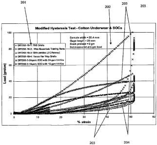
Modified Hysteresis Test
The Modified Hysteresis Test is identical to the Hysteresis Test described
above with the
following exceptions: 1) the nominal force applied to remove slack in the
sample after the first
loading cycle is 0.05 N (instead of 0.112 N) and 2) the slack preload is set
at 0 g at the start of
this test. The samples were loaded to 50% strain and % set was measured during
the second
cycle loading curve at a force of 0.05 N.
Tensile to Break Test
CA 02654750 2008-12-08
WO 2007/146148 PCT/US2007/013544
24
A commercial tensile tester (e.g., from Instron Engineering Corp. (Canton, MA)
or
SINTECH-MTS Systems Corporation (Eden Prairie, MN)) is used for this test. The
instrument
is interfaced with a computer for controlling the test speed and other test
parameters, and for
collecting, calculating and reporting the data. The Peak Elongation is
measured under typical
laboratory conditions (i.e., room temperature of 20 C and relative humidity of
50%).
When a SOC is analyzed according to the Tensile to Break test, a 2.54 cm
(width) x
7.62 cm (length) sample of the SOC material is taken. The length of the SOC
sample is taken in
the cross machine direction.
Procedure:
1. Select appropriate jaws and a load cell for the test. The jaws must be wide
enough to fit the sample (e.g., at least 2.54 cm wide). The load cell is
selected so
that the tensile response from the sample tested will be between 25% and 75%
of
the capacity of the load cells or the load range used. A 5 - 10 kg load cell
is
typical.
2. Calibrate the tester according to the manufacturer's instructions.
3. Set the gauge length at 25 mm.
4. Place the sample in the flat surface of the jaws such that the longitudinal
axis of
the sample is substantially parallel to the gauge length direction.
5. Pull the sample at a constant cross head speed of 254 mm/min to 1000%
strain or
until the sample exhibits a more than nominal loss of mechanical integrity.
A computer data system records the force exerted on the sample during the test
as a function of
applied strain. From the resulting data generated, the following quantities
are reported:
1. Loads at 15%, 50% and 75% strain (N/cm)
2. Peak elongation (%) and peak load (N/cm)
Peak elongation is the strain at peak load. Peak load is the maximum load
observed during the
Tensile to Break test.
Hydrostatic Head (Hydrohead) Pressure
The property determined by this test is a measure of the liquid barrier
property (or liquid
impermeability) of a material. Specifically, this test measures the
hydrostatic pressure the
material will support when a controlled level of water penetration occurs. The
hydrohead test is
performed according to EDANA 120.2-02 entitled "Repellency: Hydrostatic Head"
with the
following test parameters. A TexTest Hydrostatic Head Tester FX3000 (available
from Textest
AG in Switzerland or from Advanced Testing Instruments in Spartanburg, SC,
USA) is used.
CA 02654750 2008-12-08
WO 2007/146148 PCT/US2007/013544
For this test, pressure is applied to a defined sample portion and gradually
increases until water
penetrates through the sample. The test is conducted in a laboratory
environment at 22f2 C
temperature and 50% relative humidity. The sample is clamped over the top of
the column
fixture, using an appropriate gasketing material (o-ring style) to prevent
side leakage during
testing. The area of water contact with the sample is equal to the cross
sectional area of the
water column, which equals 28 cm2. Water inside the column is subjected to a
steadily
increasing pressure, which pressure increases at a rate of 20 mbar/min. When
water penetration
appears in three locations on the exterior surface of the sample, the pressure
(measured in mbar)
at which the third penetration occurs is recorded. If water immediately
penetrates the sample
(i.e., the sample provided no resistance), a zero reading is recorded. For
each material, three
specimens are tested and the average result is reported.
Moisture Vapor Transmission Rate Test
This method is applicable to thin films, fibrous materials, and multi-layer
laminates of
the foregoing. The method is based on ASTM Method E96-66. In the method, a
known amount
of a desiccant (CaC12) is put into a cup-like container. A sample of the outer
cover material to
be tested (sized to 38 mm x 64 mm, being sufficiently large to cover the
opening of the
desiccant container) is placed on the top of the container and held securely
by a retaining ring
and gasket. The assembly is placed in a constant temperature (40 C) and
humidity (75% RH)
chamber for 5 hours. The amount of moisture absorbed by the desiccant is
determined
gravimetrically and used to calculate the moisture vapor transmission rate
(MVTR) of the
sample. The MVTR is the mass of moisture absorbed divided by the elapsed time
(5 hours) and
the open surface area at the interface between the container and the sample.
The MVTR is
expressed in units of g/m2=day. A reference sample, of established
permeability, is used as a
positive control for each batch of samples. Samples are assayed in triplicate.
The reported
MVTR is the average of the triplicate analyses, rounded to the nearest 100
g/m2=day. The
significance of differences in MVTR values found for different samples can be
estimated based
on the standard deviation of the triplicate assays for each sample.
Opacity
The opacity value of a material is inversely proportional to the amount of
light that can
pass through the material. The opacity is determined from two reflectance
measurements on a
material sample.
CA 02654750 2008-12-08
WO 2007/146148 PCT/US2007/013544
26
To determine the opacity of an outer cover, an appropriately sized sample
(based on the
measurement opening of the color measurement instrument; a 12 mm diameter for
the
instrument used herein) is cut from the outer cover and first backed with a
black plate. A first
color reading is taken with the black-backed sample to detexmine a first CIE
tristimulus value
Yi. The black backing is removed and the sample is then backed with a white
plate. A second
color reading is taken with the white-backed sample to determine a second CIE
tristimulus value
Y2. The opacity is expressed as the ratio of the two readings: Opacity (%) =
Yi/YZ x 100%.
The opacity values reported herein were determined with a HUNTERLAB LABSCAN XE
(model LSXE, available from Hunter Associates Laboratory, Inc., Reston, VA).
However, other
instruments capable of determining CIE tristimulus values are also suitable.
EXAMPLES
In the following, the properties for each sample prepared for a given example
are not
necessarily reported for each sample parameter measured. In such case, the
omission of a
sample from a particular data table indicates that the omitted sample was not
evaluated for the
properties listed in the data table.
Example 1
Sample 1 A was a spunbond material fonned from a layer of elastomeric fibers
("Sel";
V2120 fiber-grade VISTAMAXX elastomeric polypropylene) having a basis weight
of 30 g/m2.
Sample 1B was a composite nonwoven material formed from a layer of elastic
meltblown fibers
("M,,"; V2120 elastomeric polypropylene) having a basis weight of 4 g/m2 in
between two
layers of elastic spunbond fibers (V2120 elastomeric polypropylene) each
having a basis weight
of 15 g/m2. The spunbond and meltblown fibers had nominal diameters of 20 m
or more and
I m, respectively.
Samples 1 A and I B were activated in a hydraulic press using a set of flat
plates (pitch of
0.100" or 2.5 mm), to a depth of engagement of 2.5 mm in either the CD only or
in both MD and
CD. Figures 1 and 2 are the SEMs of Sample 1B prior to and after activation,
respectively. The
changes in sample dimensions produced during mechanical activation were
subsequently
subjected to a Hysteresis Test omitting the prestrain loading cycle to
determine the post-
activation, first cycle % set, and the results are summarized in Table 1
Table 1
Sample Material Basis Wei ht % Set (CD) After % Set (CD)After
CA 02654750 2008-12-08
WO 2007/146148 PCT/US2007/013544
27
Activation in CD Activation in MD/CD
IA Sel 30 g/mZ 21.0 % 21.3%
1B S.A1S., 34 g/mZ 11.0 o0 11.9%
The results in Table 1 illustrate the ability of the interlayer meltblown
fibers to increase the
ability of the nonwoven to undergo recovery of the SOC by substantially
reducing the % set
produced during activation. They suggest that the meltblown layer helps
maintain the
mechanical integrity of the nonwoven material during mechanical activation. In
both cases, the
softness of the nonwoven material is improved after activation.
Example 2
Sample 2A was a spunbond material formed from two superimposed layers of
elastomeric fibers (V2120 fiber-grade VISTAMAXX elastomeric polypropylene)
each having a
basis weight of 30 g/m2. Sample 2B was a thermally bonded composite nonwoven
material
formed from a layer of elastic nanofibers ("Nei"; V2120 elastomeric
polypropylene) having a
basis weight of 5 g/m2 in between two layers of elastic spunbond fibers (V2120
elastomeric
polypropylene) each having basis weight of 30 g/mz. The spunbond and meltblown
fibers had
nominal diameters of 20 m or more and less than 1 .m, respectively.
Samples 2A and 2B were analyzed according to the opacity test. Figure 3 is the
SEM of
Sample 2B prior to mechanical activation. The results are summarized in Table
2.
Table 2
(%)
Sample Material Basis Weight Opacity
2A S.1 60 g/m2 43 %
2B S~,Ne,Sel 65 g/m2 52 %
The results in Table 2 illustrate the ability of the interlayer nanofibers to
improve the aesthetic
properties of the SOC by substantially increasing the opacity of the nonwoven
material. Based
on this data, a projected total of 10 g/m2 to 20 g/m2, for example 15 g/mZ of
ineltblown fibers
would suffice to reach an opacity of at least 65% for the nonwoven material,
prior to activation,
in the relaxed state.
Example 3
The samples of Example 3 illustrate the tensile properties of nonwoven
plastoelastic
materials formed from a mixture of elastomeric fibers (V2120 fiber-grade
VISTAMAXX
CA 02654750 2008-12-08
WO 2007/146148 PCT/US2007/013544
28
elastomeric polypropylene) and plastic fibers (polyolefin-based). Table 3A
lists the various
samples tested, the approximate relative amounts of elastomeric fibers and
plastic fibers in each
sample, and the nominal basis weights of the mixed fiber sample.
Table 3A
Target Elastomeric Plastic
Sample Basis Weight Component Component
3A 25 g/ma 100 wt.% 0 wt.%
3B 25 g/mZ 50 wt.% .50 wt.%
3C 35 g/mZ 50 wt.% 50 wt.%
3D 45 g/m2 50 wt.% 50 wt.%
3E 25g/m2 58 wt.% 42 wt.%
3F 35 g/mZ 58 wt. /u 42 wt.%
3G 45 g/m2 58 wt.% 42 wt.%
The tensile properties of Samples 3B-3G were tested after activation in both
the CD and
MD using a set of flat plates placed in a hydraulic press. Activation was
performed at
intermediate strain rate values and a depth of engagement of 2.5 mm. Table 3B
summarizes
results in terms of the sample tested, its actual basis weight, and the
direction in which the
tensile property was determined. The tensile properties were determined using
standard
EDANA methods and an MTS ALLIANCE RT 1/2 tensile testing apparatus (available
from
MTS Systems Corp., Eden Prairie, MN) equipped with pneumatic grips operating
at
254 mm/min for a gage length of 25 mm and a sample width of 25 mm.
Table 3B
Actual Peak Load Peak Stress Strain at
Sample Basis Weight Direction (N/cm) ~MPa} Break (%)
3B 25 g/mZ CD 2.47 9.07 -300-400
3C 36 g/mZ CD 4.21 10.3 326
3D 49 g/mZ CD 5.43 10.0 -300-400
3E 26 g/rn2 CD 2.01 7.00 -350-400
3E 25 g/m2 MD 5.71 21.1 235
3F 36 g/m2 CD 3.60 8.84 329
3G 46 g/m2 CD 4.99 9.60 285
Samples 3A and 3E were also subjected a Hysteresis Test, the results of which
are shown
in Table 3C. The "% set" value is the first cycle % set. The samples were
subjected to the
Hysteresis Test as described in the Test Methods section, with the exception
that the pre-
CA 02654750 2008-12-08
WO 2007/146148 PCT/US2007/013544
29
activated samples were not prestrained during the test. The "maximum load"
value represents
either the force at 200% strain for the unactivated sample during the
prestrain cycle or the force
at 75% strain for the activated samples during the first loading cycle. The
activated samples
were tested after activation in both the CD and MD in a benchtop hydraulic
press having a depth
of engagement of 2.5 mm.
Table 3C
Actual 15t Strain Cycle 2 d Strain Cycle
Basis
Sample Act. Weight % Set Maximum Load 50% Load 75% Relax. 20% Load 75% Relax.
3A N 25 g/m2 33.4 3.09 N 0.37 N 46.5% 0.04 N 36.2 00
3A Y 18 g/m2 17.2 0.64 N 0.26 N 50.6% 0.03 N 35.5%
3E Y 24 g/m2 25.7 0.64 N 0.25 N 47.9% 0.01 N 33.7%
Samples 3E-3G were also subjected to a high strain rate activation test, using
a High-
Speed Research Press ("HSRP"). During the test, the force applied to a
nonwoven material
sample was measured while the material was elongated up to a strain of 1000%
at strain rates up
to 1000 s 1 using two flat ring-roll plates having a depth of engagement of
8.2 mm and a pitch of
1.5 mm. The samples were essentially completely shredded at the end of the
test. The resulting
data (i.e., applied force as a function of strain at a fixed strain rate) were
analyzed to identify the
strain at which the applied force was at a maximum. When the normalized
applied force (i.e.,
applied force per unit weight of the nonwoven sample) is at a maximum, the
nonwoven material
loses its ability to withstand additional loading without an increased
likelihood of material
destruction. The strain at the maximum applied force represents the ability of
the nonwoven
material to withstand the mechanical activation process having approximately
the same degree
of strain. Table 3D summarizes the results of these tests.
Table 3D
Strain Maximum Strain at
_ Sample Strain Rate Direction Applied Force Max. Force
3E = = 1000 s"I CD 17 kN/g 200%
3F 1000 s'l CD 18 kN/g 200%
3G 1000 s"l CD 19 kN/g 190%
3E 500 s'l Mlb 35 kN/g 180%
3E 500 s"' CD 15 kN/g 280%
CA 02654750 2008-12-08
WO 2007/146148 PCT/US2007/013544
The results in Table 3D suggest that the plastoelastic materials of the
present disclosure are
capable of withstanding a mechanical activation process at strain levels up to
200%, for example
up to 300%, while incurring only minimal damage, even at very high strain rate
conditions. This
is in contrast to typical commercial extensible nonwoven materials that can
only withstand
strains up to 150% when subjected to comparable strain rates.
The activation process also improves the softness and feel of the
plastoelastic nonwoven
material. This effect is largely related to the increase in web loft/thickness
created during the
activation process. Figures 6-9 illustrate this effect for the nonwoven
plastoelastic materials of
Example 3. Figures 6 and 7 are SEMs of a bonded plastoelastic nonwoven
material prior to
activation (top and side views, respectively). Figures 8 and 9 are SEMs of the
same nonwoven
material after activation (top and side views, respectively), and they
illustrate the increased
thickness of the material.
Example 4
The samples of Example 4 illustrate the tensile properties of composite
nonwoven
plastoelastic materials formed from a layer of plastoelastic bi-component
spunbond fibers and a
layer of elastic spunbond fibers. V2120 fiber-grade VISTAMAXX elastomeric
polypropylene
was used as the elastic component of the bi-component fibers and for the
elastic fibers
themselves. For samples 4A-4D, the plastic component of the bi-component
fibers was a
mixture of PH-835 Ziegler-based polypropylene (50 wt.%; available from Basell
Polyolefins,
Elkton, MD) and HH-441 high melt flow rate polypropylene (50 wt.%; melt flow
rate =
400 g/10 minutes; available from Himont Co., Wilmington, DE). For samples 4E-
4G, the
plastic component of the bi-component fibers was a Basell Moplen 1669 random
polypropylene
copolymer with a small amount of polyethylene (also available from Basell
Polyolefins). The
bi-component fibers had an elastomeric core and a plastic sheath, and the
weight fraction of each
component is given in Table 4. The elastic fibers also contained 3.5 wt.% of
an anti-blocking
agent to improve their spinning performance. Each of the two spunbond layers
represents half
of the total basis weight of the nonwoven material (i.e., the value listed in
the second column of
Table 4). The two spunbond layers were thermally bonded using two heated
rolls, with the first
at 84 C, and the second at 70 C.
Table 4 summarizes the tensile properties of the spunbond-spunbond composites
tested
in an unactivated state. The properties were determined with standard EDANA
methods
CA 02654750 2008-12-08
WO 2007/146148 PCT/US2007/013544
31
(EDANA method 40.3-90 for the basis weight and EDANA method 20.2-89 for the
tensile
properties).
Table 4 also summarizes properties of the composites as measured by a
hysteresis test.
The Hysteresis Test described in the "Test Methods" section above was modified
in the
following aspects: (1) sample size (5 cm wide x 15 cm long), (2) crosshead
speed
(500 mm/min), (3) prestrain loading/unloading (omitted), and (4) first and
second cycle
loading/unloading (100% maximum strain, held for 1 second at maximum strain,
held for
30 seconds after unloading). For each cycle, Table 4 provides the force at
100% strain
(normalized by the sample width) and the % set after unloading. For the first
cycle, the % set is
the strain after the first cycle unloading. For the second cycle, the % set is
the relative increase
in strain between the unloaded states of the first and second cycles. For
example, a sample with
an initial length of 10 cm, a first unload length of 15 cm, and a second
unload length of 18 cm
would have a first cycle % set of 50% and a second cycle % set of 20%.
Table 4
Core Sheath Tensile Stress Elongation Load at 100%
(N/50 mm) ~%) Strain (N/50 mm) % Set
Basis Weight
Wt. Ratio lst 2nd lst 2nd
Sample (g/m2) (%/%) CD MD CD MD Cycle Cycle Cycle Cycle
4A 37.5 80/20 11.9 17.9 106 101 11.4 9.58 70 17
4B 38.8 90/10 8.50 12.8 152 155 7.68 6.76 59 19
4C 58.7 80/20 20.2 29.2 133 139 18.7 16.4 68 20
4D 60.7 90/10 18.7 24.2 144 133 14.4 12.7 57 21
4E 44.8 90/10 8.00 11.0 145 133 6.70 5.80 45 8
4F 66.7 90/10 14.6 18.7 158 146 12.9 11.0 52 16
4G 59.7 80/20 18.0 24.8 102 100 18.1 15.7 61 17
The results in Table 4 indicate that a mechanically activated SOC formed from
the plastoelastic
materials of the present disclosure has favorable stretch properties, and
wbuld be able to exhibit
% set values less than 20%, and as low as less than 10%.
Example 5
The samples of Example 5 illustrate the tensile properties of plastoelastic
film materials
formed with an elastomeric component (V 1100 film-grade VISTAMAXX elastomeric
polypropylene), plastic components (polyolefin-based), and an optional
opacifier. The various
plastic components are summarized in Table 5A and include linear low density
polyethylene
CA 02654750 2008-12-08
WO 2007/146148 PCT/US2007/013544
32
(LL6201), low molecular weight polyethylene waxes (A-C 617, A-C 735, and
PARVAN 1580),
and a low molecular weight polypropylene wax (LICOWAX PP230). The unactivated
samples
were tested to determine their tensile properties and then subjected to a
Hysteresis Test with the
following modification: the test included only a prestrain and a first cycle
loading (with a
maximum strain of 50% and a 30 second hold time. The results of this test are
provided in
Tables 5B and 5C. It should be noted that the Sample designations represent a
sample prepared
according to the formulation shown in the table. The sample is then subjected
to a particular
test. As a result, the physical parameters of the samples, such as basis
weight, may vary even
though the sample designation is the same. For example, Sample 5E shown in
Table 5B lists a
different basis weight than Sample 5E in Table 5C.
Table 5A
V1100 LL6201 AC 735 AC 617 P. 1580 PP 230 Ti02
Samnle (wt.%) (wt.%) (wt.%) (wt.%) (wt.%) (wt.%) (wt.%)
5A 60 10 10 20
5B 60 10 10 20
5C 60 10 10 20
5D 58.8 9.8 9.8 19.6 2.0
5E 85 15
Table 5B
Peak Load Peak Stress Strain at
Sample Basis Weight Direction (Nlcm) (MPa) Break (%)
5A 16 g/mZ CD 6.8 15 741
5B 24 g/m2 CD 10.5 14 636
5C 19 g/mZ CD 8.0 15 755
5E 29 g/m2 CD 20.7 23 848
Table 5C
1st Strain Cycle
Film Basis Prestrain
Sample Thickness Weight % Set 200% Load 50% Load 50% Relax. 30% Unload
5A 13 m 16 g/m2 33.7 1.36 N 0.6 N 31.5% 0.15 N
5B 22 4m 24 g/m2 27.3 2.07 N 0.9 N 30.7% 0.25 N
5C 20 m 20 g/m2 41.8 2.03 N 0.9 N 33.9% 0.20 N
5D 25 m , 24 g/m2 32.3 2.50 N 1.1 N 32.7% 0.23 N
5E 13 m 14 g/m2 32.0 1.50 N 0.5 N 76.1% 0.05 N
CA 02654750 2008-12-08
WO 2007/146148 PCT/US2007/013544
33
The results in Table 5A-5C illustrate that the plastoelastic film formulations
of the present
disclosure have favorable mechanical properties that make them suitable for
inclusion into a
SOC.
Example 6
The samples of Example 6 illustrate the tensile properties of an elastic film
formed with
elastomeric components, anti-blocking agents, and an opacifier (titanium
dioxide). The various
components are summarized in Table 6A and include elastomeric polypropylene (V
1100 film-
grade VISTAMAXX), styrenic block copolymers (VECTOR V4211 and PS3190
(available
from Nova Chemicals, Pittsburgh, PA)), a soft polypropylene-based
thermoplastic elastomer
reactor blend (ADFLEX 7353, available from Basell Polyolefins, Elkton, MD),
and anti-
blocking agents (CRODAMIDE and INCROSLIP, both available from Croda, Inc.,
Edison, NJ).
The unactivated samples were tested to determine their tensile properties and
then subjected to a
Hysteresis Test modified as described in example 5 (i.e., including only a
prestrain and a first
cycle loading (with a maximum strain of 50% and a 30 second hold time)), the
results of which
are provided in Tables 6B and 6C. It should be noted that the Sample
designations represent a
sample prepared according to the formulation shown in the table. The sample is
then subjected
to a particular test. As a result, the physical parameters of the samples,
such as basis weight,
may vary even though the sample designation is the same. For example, Sample
6B shown in
Table 6B lists a different basis weight than Sample 6B in Table 6C.
Table 6A
V1100 V4211 PS3190 Adflex Crodamide Incroslip B TiOZ
Sample (wt.%) (wt.%) (wt.%) (wt.%) (wt.%) (wt.%) (wt.%)
6A 41.7 37.0 6.5 5.55 5.55 3.7
6B 75.6 8.4 5.5 6.8 3.7
6C 85.7 4.0 6.7 3.6
Table 6B
Peak Load Peak Stress Strain at
Sample Basis Weight Direction (N/cm) (MPa) Break (%)
6A 31 g/m2 CD 16.5 21 731
6B 25 g/mZ CD 11.0 15 623
CA 02654750 2008-12-08
WO 2007/146148 PCT/US2007/013544
34
Table 6C
l6t Strain Cycle
Film Basis Prestrain
Sample Thickness Weight % Set 200%%ad 50% Load 50% Relax. 30% Unload
6A 25 m 31 g/m2 11.6 2.30 N 1.17 N 21.6% 0.51 N
6B 20 m 21 g/mZ 14.8 1.70 N 0.90 N 21.1% 0.39 N
6C 20 m 21 g/m2 19.2 1.86 N 0.90 N 23.1% 0.35 N
The results in Tables 6A-6C illustrate that the elastic film formulations of
the present disclosure
have favorable mechanical properties that make them suitable for inclusion
into a SOC when
combined with a nonwoven material into a laminate structure.
Example 7
The samples of Example 7 illustrate the effect of including a plasticizer on
the tensile
properties of an elastic film. The various components are summarized in Table
7A. The
plasticizer used was mineral oil, and the mineral oil was added to the
formulation by heating the
V 1100 elastomeric polypropylene at 50 C while in contact with the oil. The
unactivated
samples were then subjected to a Hysteresis Test (modified as described in
examples 5 and 6),
the results of which are provided in Table 7B.
Table 7A
V1100 Min. Oil Crodamide lncroslip B TiOZ
Sample (wt.%) (wt.%) (wt.%) (wt.%) (wt.%)
6A 80 6 6 8
6C 60 20 6 6 8
Table 7B
Film Basis 15` Strain Cycle
Prestrain
Sample Thickness Weight % Set 200% Load 50% Load 50% Relax. 30% Unload
7A 20 m 21 g/mZ 19.2 1.86 N 0.9 N 23.1% 0.35 N
7B 15 m 14 g/mZ 17.9 0.48 N 0.2 N 17.8% 0.11 N
The results in Tables 7A-7B illustrate that the inclusion of a plasticizer
into the film
formulations of the present disclosure can substantially reduce the
loading/unloading forces
while retaining favorable % set values.
CA 02654750 2008-12-08
WO 2007/146148 PCT/US2007/013544
Example 8
The samples of Example 8 illustrate the effect of including filler particles
on the
breathability and the tensile properties of a plastoelastic film formed with
an elastomeric
component (V 1100 film-grade VISTAMAXX elastomeric polypropylene and,
optionally,
VECTOR V4211 styrenic block copolymer), a plastic component (LL6201 linear low
density
polyethylene), calcium carbonate filler particles, and titanium dioxide
opacifying particles. The
samples were tested after activation in the CD only at strain rates of 500 s 1
and a depth of
engagement of 4.4 mm for a pitch of 3.8 mm (0.150"). The formulations and
resulting
properties are show in Tables 8A and 8B. The samples listed in Table 8B were
subjected to a
Hysteresis Test (modified as described in examples 5 and 6).
Table 8A
Film
V1100 V4211 LL6201 CaCO3 Ti02 Thickness MVTR
Sample (wt.%) (wt.%) (wt.%) (wt.%) (wt.%) ( m) (g/mZ.d)
8A 30 20 48 2 30 1727
8B 32 16 50 2 30 2064
8C 33 13 52 2 46 1746
8D 34 10 54 2 33 1908
8E 35 7 56 2 30 1056
8F 38 60 2 48 206
8G 37 10 51 2 25 348
8H 44 10 44 2 25 197
81 42 10 46 2 38 209
8J 28 6 10 54 2 25 2989
Table 8B
Basis is` Strain Cycle
Arestrain
Sample Weight % Set 200% Load 50% Load 50% Relax. 30% Unload
8A 43 g/mZ 55.3 3.31 N 2.0 N 33.9% 0.26 N
8B 41 g/m2 51.1 3.22 N 1.8 N 33.4% 0.26 N
8C 59 g/mZ 65.5 4.02 N 2.6 N 35.9% 0.36 N
8D 48 g/mZ 36.3 2.93 N 1.3 N 31.2% 0.29 N
8E 42 g/mZ 30.0 2.30 N 1.0 N 28.9% 0.27 N
8F 68 g/m2 26.1 3.34 N 1.4 N 28.0% 0.43 N
CA 02654750 2008-12-08
WO 2007/146148 PCT/US2007/013544
36
The results in Tables 8A-8B illustrate that the inclusion of filler particles
into the film
formulations of the present disclosure can substantially increase the
breathability of the film
while retaining favorable mechanical properties.
Table 9 and FIG. 4 show comparative data for 6 samples 201. The data graphs
202 of
the results can be seen in FIG. 4. The samples 201 included four commercial
brands of
underwear 203 and two stretchable outer covers 204 according to at least one
embodiment of the
invention. The samples 201 were measured according to the Modified Hysteresis
Test described
in the Test Methods section. The measurements on the underwear samples 203
were made in
the lateral direction (i.e., the direction substantially parallel to the
waistband of the underwear).
Commercial underwear 203 typically have more stretch in the lateral direction
than the
longitudinal direction, but still exhibit suitable low-force, recoverable-
stretch properties in the
longitudinal direction.
Table 9
ID Description First Cycle Load at % set
iven strain m/cm
15% 25% 50% .05 N
Target <20 <40 <20
GRT292- TKS Basics Toddler Boys Brief 3.0 5.7 17.5 14.9
16-1 2T/3T
GRT292- WEE ESSENTIALS Padded 3.4 7.1 21.1 14.8
16-2 Training Pants, 3T (Distributed by
JC PENNEY)
GRT292- JC PENNEY White Panties Girl, 8.1 16.5 47.6 11.3
16-3 2T/3T, # 344 11108003 05
.GRT292- HANES HER WAY CLASSICS 18.1 36.6 97.8 10.7
16-4 Brief Size 4 (UPC: 75338 30388)
GRT285-3- 24 g/m solid VISTAMAXX 1100 18.6 28.3 39.2 7.9
24 g/ma film + H2031 adhesive + 2 layers of
25 g/ma DAPP NW; Activation in
the hydraulic press (P=0.100",
DOE=0.158"
GRT285-3- 15 g/m solid VISTAMAXX 1100 9.8 17.1 25.4 7.8
15 g/m2 film + H2031 adhesive + 2 layers of
25 g/ma DAPP NW; Activation in
the hydraulic press (P=0.100",
DOE=0.158")
Table 10 and FIG 9 show comparative opacity data for various basis weight
nonwoven
substrates. FIG 9 shows a nanofiber trendline 302 and a standard meltblown
fiber trendline 303.
The nanofiber trendline 302 was produced from the nanofiber datapoints 305
corresponding to
CA 02654750 2008-12-08
WO 2007/146148 PCT/US2007/013544
37
the nanofiber substrates labeled as samples 1- 9 in Table 10. Samples 1- 10 in
Table 10
correspond to an unbonded spundbond-nanofiber-spunbond substrate. The basis
weights for
each individual layers is listed in the ID column. The basis weights were
measured in gram per
square meter ("gsm"). The Total Basis weight corresponds to the sum of the
individual layer
basis weights. The standard meltblown fiber trendline 303 was produced from
the standard
meltblown datapoints 306 corresponding to the standard meltblown substrates
labeled as sample
11 - 17 in Table 10. The standard rneltblown fiber substrates are commercially
available
substrates. The basis weight of each layer is listed in the ID column. As can
be seen from the
data a nonwoven substrate comprising nanofibers may provide improved opacity
over a standard
nonwoven substrate for a given basis weight.
Table 10
Fine
Fiber
BW Total Basis
Sample # ID sm weight (gsm) Opacity
1 SN+S 13.5/2.36/13.5 UNBONDED 2.36 29.4 53.9
2 SN+S 13.5/2.03/13.5 UNBONDED 2.03 29 53.2
3 SN+S 13.5/7.6/13.5 UNBONDED 7.6 34.6 74.4
4 SN+S 13.5/0.55/13.5 UNBONDED 0.55 27.6 44.2
SN+S 13.5/1.07/13.5 UNBONDED 1.07 28.1 51.7
6 SN+S 13.5/3.1/13.5 UNBONDED 3.1 30.1 65.1
7 SN+S 12/4/03 2:35 13.5/0.94/13.5
UNBONDED 0.94 27.9 44.2
8 SN+S 12/4/03 2:44 13.5/2.31/13.5
UNBONDED 2.31 29.3 54.3
9 SN+S 12/4/03 2:26 13.5/0.58/13.5
UNBONDED 0.58 27.6 43.2
FIBERTEX 22GSM 10/1/1/10
H1502220 W/TI02 2 22 50.6
11 FQN 7/3/7 SMS 3 17 30.4
12 FQN HIGH OPACITY 7.5/5/7.5 W/
T102 5 20 46..3
13 FQN C123 SMS 11/8/11 W/ T102 8 30 62.4
14 FQN SBC SMS 6/5/6 MB=2.5MIC 5 17 40.2
7/3/7 SMS FIBERTEX
ELITE 1.5MB,12MB 3 17 31.6
16 30 13/4/13 SMS FQN 4 30 41.6
17 7/3/7 SMS BBA TORONTO 3 17 30.4
The dimensions and values disclosed herein are not to be understood as being
strictly
limited to the exact numerical values recited. Instead, unless otherwise
specified, each such
dimension is intended to mean both the recited value and a functionally
equivalent range
surrounding that value. For example, a dimension disclosed as "40 mm" is
intended to mean
CA 02654750 2008-12-08
WO 2007/146148 PCT/US2007/013544
38
"40 mm."
All documents cited in the Detailed Description of the Invention are, in
relevant part,
incorporated herein by reference; the citation of any document is not to be
construed as an
admission that it is prior art with respect to at least one embodiment of the
invention. To the
extent that any meaning or definition of a term in this written document
conflicts with any
meaning or definition of the term in a document incorporated by reference, the
meaning or
definition assigned to the term in this written document shall govern.
While particular embodiments of the invention have been illustrated and
described, it
would be obvious to those skilled in the art that various other changes and
modifications can be
made without departing from the spirit and scope of the invention. It is
therefore intended to
cover in the appended claims all such changes and modifications that are
within the scope of this
invention.