Note: Descriptions are shown in the official language in which they were submitted.
CA 02654795 2008-12-08
WO 2007/147008 1 PCT/US2007/071131
REFORMED ALCOHOL POWER SYSTEMS
BACKGROUND OF THE INVENTION
[0001] This invention is generally related to power
systems utilizing alcohol reforming, and more particularly,
to the efficient reforming of alcohols to produce hydrogen-
containing gas mixtures to use as fuel in internal combustion
engines such as those used to generate electrical or
mechanical power in vehicular power systems.
[0002] In transportation applications, alcohols,
particularly ethanol, are garnering increased interest as an
alternative to fossil fuels for internal combustion engines.
Ethanol is a renewable fuel, typically derived from
fermentation of agricultural biomass. Unlike fossil fuels,
the carbon dioxide liberated during the combustion of ethanol
does not represent an increase in greenhouse gases because
the carbon atoms released during combustion represent
atmospheric carbon dioxide fixed by plants from which the
ethanol is derived.
[0003] However, there are difficulties associated with
the use of alcohol fuels in internal combustion engines. The
lower heating values of methanol (15.9 MJ/liter) and ethanol
(21.3 MJ/L) are substantially less than that of conventional
gasoline (32 MJ/liter) as reported by F. Black in "An
Overview of the Technical Implications of Methanol and
Ethanol as Highway Vehicle Fuels," SAE Paper 912413, 1991.
Thus, a greater volume of alcohol fuel is necessary if
utilized with equal efficiency, which reduces the value of
ethanol to the consumer on a volumetric basis.
[0004] Moreover, cold start is a problem for alcohol-
fueled engines because at low temperature the fuel lacks
sufficient vapor pressure to form an ignitable mixture.
Anhydrous ethanol engines cannot start at ambient
temperatures below about 15 C (59 F). Ethanol, therefore, is
CA 02654795 2008-12-08
WO 2007/147008 2 PCT/US2007/071131
usually blended with gasoline in the United States
(typically, 15% gasoline in E85 blend), so that the gasoline
can initiate combustion in cold temperature operating
environments. E85 engines can achieve cold start at low
temperatures by massive overfueling in order to force enough
volatile fuel into the cylinder to achieve ignition. This
results in high levels of hydrocarbon and carbon monoxide
emissions, a problem which is significantly aggravated by the
fact that the catalytic converter is not yet at operating
temperature. (See J. Ku et. al., "Conversion of a 1999
Silverado to Dedicated E85 With Emphasis on Cold Start and
Cold Driveability", SAE 2000-01-0590, 2000). Moreover, cold
start problems may persist even using E85 and similar fuel
blends at lower temperatures. As a solution to the cold
start-up problem, G.W. Davis et al. suggest in Proc.
Intersoc. Energy Conver. Eng. Con., 2000, 35, pp. 303-8 to
supplement the E85/air mixture with hydrogen.
[0005] The two most important variables determining the
efficiency of an internal combustion engine are the expansion
ratio and the air:fuel ratio. The expansion ratio is the
ratio of the volume in the cylinder at the time the exhaust
valve opens to the volume at maximum compression. The
expansion ratio is often, but not always, equivalent to the
compression ratio. An engine's compression ratio is the
ratio of the volume between the piston and cylinder head
before and after the compression stroke. The air:fuel ratio
is sometimes expressed as A and sometimes as the equivalence
ratio, denoted by T. Lambda (A) is calculated by dividing
the actual air:fuel ratio by the stoichiometric ratio of
air:fuel for the fuel being combusted. The equivalence ratio
is calculated by dividing the actual fuel:air ratio by the
stoichiometric fuel:air ratio for the fuel being combusted.
CA 02654795 2008-12-08
WO 2007/147008 3 PCT/US2007/071131
[0006] Internal Combustion Engine Fundamentals by John
B. Heywood (McGraw Hill, New York, 1988) describes the effect
of expansion ratio and equivalence ratio on internal
combustion engine efficiency. Increasing an engine's
expansion ratio improves efficiency as does increasing A.
Increasing A above 1.0 corresponds to using "leaner" fuel-air
mixtures (i.e., mixtures with an excess of air over that
required by stoichiometry).
[0007] The maximum attainable compression ratio is set
by the knock limit. Increasing compression leads to
increased temperature and pressure of the gas in the cylinder
that causes spontaneous, premature ignition known as "knock."
The ability of a fuel to resist knock is quantified by its
octane number. Both methanol and ethanol are relatively high
octane fuels, but methane, hydrogen, and carbon monoxide are
more resistant to knock and therefore can be utilized with
high efficiency in an internal combustion engine operated
with a high compression or expansion ratio.
[0008] Lean combustion improves fuel efficiency in part
because it ensures complete combustion of the fuel, but
primarily by reducing the temperature of the combusted gas.
The lower temperature reduces heat loss to the cylinder walls
and improves the thermodynamic efficiency with which the gas
does work on the piston. For example, J. Keller et al.
report in SAE Special Publication 1574, 2001, pp. 117-22 that
operating a four-stroke, spark-ignited internal combustion
engine using hydrogen as a fuel under lean conditions
(equivalence ratio = 0.35-0.45, corresponding A= 2.2-2.9)
and high compression ratio (up to 20) results in thermal
efficiencies of up to 47%. A further advantage of low
temperature combustion is the fact that formation of nitrogen
oxides (NOX) is minimized.
CA 02654795 2008-12-08
WO 2007/147008 4 PCT/US2007/071131
[0009] When the air:fuel ratio becomes too lean (and
the gas temperature too cool) the mixture will fail to ignite
or "misfire." Alternatively, the mixture may burn too slowly
or incompletely. Because hydrogen will burn in air at
concentrations down to about 4% and exhibits a high flame
velocity, aiding rapid and complete combustion,
supplementation of the fuel with hydrogen allows for reliable
operation under lean conditions. As reported by C.G. Bauer
et al. in Int. J. Hydrogen Energy, 2001, 26, 55-70, the
burning speeds of hydrogen, methane, and gasoline in air at
normal temperature and pressure (NTP) are 264-325, 37-45 and
37-43 cm/sec, respectively.
[0010] Reforming alcohols is an alternative to
combusting alcohol fuels directly in an internal combustion
engine. In a reforming process, the alcohol is decomposed
into permanent gases that can be fed to an internal
combustion engine. L. Pettersson reports in Combust. Sci.
and Tech., 1990, pp. 129-143, that operating an internal
combustion engine on reformed methanol rather than liquid
methanol can improve efficiency. The key factors responsible
for the improved efficiency are the high air:fuel ratio, the
increase in the heat of combustion of reformed alcohols
compared to non-reformed alcohols, and the ability to use
higher compression ratios.
[0011] It is known that starting an internal combustion
engine on a mixture of permanent gases produced by methanol
reforming is easier than starting on liquid methanol fuel
when the ambient temperature is low. For example, L. Greiner
et al. report in Proceedings of the International Symposium
on Alcohol Fuels Technology, 1981, paper 111-50, CAS no.
1981:465116, that ignition and continuous run at -25 C can be
achieved by reforming methanol using heat from electric
current provided by a battery. However, the battery quickly
discharges, forcing an early and difficult transition to the
CA 02654795 2008-12-08
WO 2007/147008 5 PCT/US2007/071131
use of liquid methanol fuel and eliminating any energy
efficiency advantage associated with the use of reformed
methanol as a fuel.
[0012] In U.S. Patent No. 4,520,764, issued to M. Ozawa
et al. and in JSAE Review, 1981, 4, 7-13, authored by T.
Hirota, the use of reformed methanol to fuel an internal
combustion engine at startup and during steady-state
operation is reported. Engine exhaust is used to heat the
methanol reformer. Using lean combustion (A = 1.7) and a
high compression ratio (14), they achieved an excellent brake
thermal efficiency of 42%. By comparison, the maximum value
for non-reformed methanol is about 33%. Ozawa et al. report
that the engine can be started on reformate (hydrogen and CO)
stored in a pressure vessel.
[0013] Reformed methanol power systems tend to backfire
severely if the fuel-air mixture is not lean enough because
of the high hydrogen composition. L.M. Das in Int. J.
Hydrogen Energy, 1990, 15, 425-43, reports that when the
fuel-air mixture is not lean enough, severe backfiring is a
problem for engines running on hydrogen. T.G. Adams in SAE
Paper 845128, 1984, 4.151-4.157 reports that CO-H2 mixtures
from methanol reforming backfire at high concentration. As a
result, the rate at which fuel can be fed to the engine and
the engine's maximum power are limited.
[0014] Vehicular power systems including a fuel cell
fed with hydrogen to produce electrical power have also been
suggested. The fuel cell vehicle may be equipped with
pressurized tanks of stored hydrogen or with a fuel processor
capable of converting an alcohol or other liquid hydrocarbon
fuel to hydrogen. Onboard reforming of liquid fuels would
enable fuel cell vehicles to achieve ranges comparable to
gasoline-fueled automobiles.
CA 02654795 2008-12-08
WO 2007/147008 6 PCT/US2007/071131
[0015] Onboard reforming of liquid or gaseous fuels to
yield hydrogen-containing gas mixtures can be conceptually
divided into two categories depending on the temperature
required. It is both thermodynamically and kinetically
feasible to reform methanol to hydrogen and carbon monoxide
or carbon dioxide with greater than 95% conversion at
temperatures of about 300 C. A review of methanol reforming
can be found in the article "Hydrogen Generation from
Methanol" by J. Agrell, B. Lindstrom, L.J. Pettersson and
S.G. Jaras in Catalysis-Specialist Periodical Reports, 16,
Royal Society of Chemistry, Cambridge, 2002, pp. 67-132.
Morgenstern et al. describe complete conversion of ethanol to
methane, hydrogen and CO/CO2 below about 300 C. See U.S.
Patent Application Pub. No. 2004/0137288 Al; and "Low
Temperature Reforming of Ethanol over Copper-Plated Raney
Nickel: A New Route to Sustainable Hydrogen for
Transportation," Energy and Fuels, Vol. 19, No. 4, pp. 1708-
1716 (2005). Although other fuels that reform around 300 C
are known, such as glycerol, none are abundant enough to
serve as motor fuels.
[0016] Most other reforming processes are highly
endothermic and therefore require temperatures of about 700 C
because of the stability of carbon-hydrogen bonds in the
molecule. Reforming of methane and gasoline as well as high
temperature reforming of ethanol to hydrogen and carbon
monoxide are in this category. Although considerable
research has been devoted to onboard generation of hydrogen
via high temperature reforming, fueling an internal
combustion engine is not practical at high reforming
temperature, largely because of the energy cost of generating
the required heat by burning a portion of the fuel.
[0017] By contrast, fueling an internal combustion
engine with reformed methanol is known in the art and is
enabled by the fact that the reformer can be maintained at
CA 02654795 2008-12-08
WO 2007/147008 7 PCT/US2007/071131
the required temperature (typically about 300 C) by the heat
of the engine exhaust. Even so, high thermal conductivity is
required in the catalyst and reformer to effectively use
engine exhaust as a heat source. Hirota reports in JSAE
Review, 1981, 4, 7-13, that, although methanol reforming
requires a temperature of only 300 C, considering the
performance of the current reformer's heat exchanger, a
temperature difference of about 100 C between the exhaust and
catalyst is required, so that the lower limit of the exhaust
temperature is approximately 400 C. This limit corresponds
to an engine speed of about 1400 rpm under no load. Thus,
there are difficulties in the prior art in maintaining
reformer temperature (and thus catalyst activity) when the
engine is near idle.
[0018] Numerous papers have also described the high-
temperature steam reforming of ethanol to carbon monoxide and
hydrogen using alumina-supported, copper-nickel catalysts in
accordance with reaction equation (1) below. In fuel cell
power systems, it would be necessary to contact the reformate
with a suitable low-temperature water-gas shift catalyst in
accordance with reaction equation (2) to generate further
hydrogen and eliminate C0, a fuel cell poison.
CH3CH2OH (g) + H20 (g) --> 2C0 + 4H2 (1)
water-gas shift: CO + H20 _> C02 + H2 (2)
[0019] Reaction (1) is highly endothermic, which
accounts for the requirement of reforming temperatures of
about 700 C in order to fully convert ethanol to hydrogen.
The high temperature required for the reaction causes several
difficulties when attempting to utilize ethanol reformed in
this way for the generation of electrical or mechanical
CA 02654795 2008-12-08
WO 2007/147008 8 PCT/US2007/071131
power. First, as noted above, engine exhaust is not hot
enough to supply the heat required in the reformer.
Accordingly, exhaust-heated, high-temperature reforming of
ethanol for vehicular power system applications has not been
widely developed or tested. Second, catalyst deactivation
during high-temperature ethanol reforming has been reported
as severe. The major cause of deactivation is coking due to
the formation of polyethylene on the catalyst surface, which
is converted to graphite. The dehydration of ethanol to
ethylene, catalyzed by acidic sites on the support, is
believed to be the root cause of catalyst deactivation. (See
Freni, S.; Mondello, N.; Cavallaro, S.; Cacciola, G.; Parmon,
V.N.; Sobyanin, V.A. React. Kinet. Catal. Lett. 2000, 71,
143-52.) High levels of ethylene formation have been
reported on alumina-supported catalysts (See Haga, F.;
Nakajima, T.; Yamashita, K.; Mishima, S.; Suzuki, S. Nippon
Kagaku Kaishi, 1997, 33-6.)
[0020] Morgenstern et al. have explored fuel cell
vehicular power systems fed with hydrogen produced by the
low-temperature (e.g., below about 400 C) reforming of
alcohol, particularly ethanol, over a catalyst comprising
copper at the surface of a metal supporting structure (e.g.,
copper-plated Raney nickel). Morgenstern et al. propose that
low-temperature ethanol reforming may be divided into two
steps, although a concerted mechanism is also possible. In
accordance with reaction equations (3)-(5), ethanol is first
reversibly dehydrogenated to acetaldehyde, followed by
decarbonylation of acetaldehyde to form carbon monoxide and
methane. After water-gas shift, 2 moles of hydrogen are
produced per mole of ethanol.
CH3CH2OH (g) --> CH3CHO (g) + H2
AH = +68.1 kJ/mol (3)
CA 02654795 2008-12-08
WO 2007/147008 9 PCT/US2007/071131
CH3CHO (g) --> CH4 + CO
AH = -19.0 kJ/mol (4)
net after water-gas shift:
CH3CH2OH + H20 -> CH4 + CO2 + 2H2 (5)
[0021] As compared to conventional high-temperature
reforming of ethanol, which produces 6 moles of hydrogen per
mole of ethanol after water-gas shift (reaction equations (1)
and (2)), an apparent drawback of the low-temperature
reforming pathway is its low hydrogen yield, producing two
moles of hydrogen per mole of ethanol after water-gas shift.
However, Morgenstern et al. teach that onboard a fuel cell
vehicle, the methane in the reformate would pass through the
fuel cell unit without degrading its performance and the fuel
cell effluent may be fed to a downstream internal combustion
engine to capture the fuel value of the methane (along with
any residual hydrogen, ethanol and acetaldehyde). Waste heat
from the engine exhaust is used to heat the reformer and
drive the endothermic dehydrogenation of ethanol.
[0022] Despite the advantages provided in the teaching
of Morgenstern et al. and others, the commercial development
of vehicular fuel cell power systems is impeded by the
complexity and high cost of the fuel cell unit as well as
cold start and transient response issues. Storage of
hydrogen onboard the vehicle creates safety concerns and
imposes weight and cost penalties associated with the high
pressure storage tanks, as well as a loss of energy
efficiency caused by the necessity of compressing the
hydrogen to pressures of 5-10,000 psi.
[0023] Accordingly, a need persists for reformed
alcohol power systems in vehicular and other applications
that use an internal combustion engine for primary power
CA 02654795 2008-12-08
WO 2007/147008 10 PCT/US2007/071131
generation and effectively exploit the fuel value of alcohols
with high efficiency to enable cold start-up without blending
conventional gasoline and allow for leaner air:fuel operation
of the internal combustion engine.
SUMMARY OF THE INVENTION
[0024] The present invention is directed to processes
for producing mechanical or electrical power from a fuel
comprising alcohol. In one embodiment, the process comprises
contacting a feed gas mixture comprising the alcohol fuel
with a reforming catalyst in a reforming reaction zone to
produce a product reformate gas mixture comprising hydrogen.
The reforming catalyst comprises a metal sponge supporting
structure and a copper coating at least partially covering
the surface of the metal sponge supporting structure. The
metal sponge supporting structure is prepared by a process
comprising leaching aluminum from an alloy comprising
aluminum and a base metal. In accordance with one
embodiment, the reforming catalyst is prepared by depositing
copper on the metal sponge supporting structure. An intake
gas mixture comprising oxygen and the product reformate gas
mixture is introduced into a combustion chamber of an
internal combustion engine and combusted to produce an
exhaust gas mixture. An exhaust gas effluent comprising the
exhaust gas mixture is discharged from the combustion chamber
and the energy of combustion is utilized for the generation
of mechanical or electrical power. The exhaust gas effluent
is brought into thermal contact with the reforming reaction
zone to heat the reforming catalyst therein.
[0025] In accordance with another embodiment of the
present invention, a process for producing mechanical or
electrical power from a fuel comprising ethanol is provided.
The process comprises contacting a feed gas mixture
comprising the ethanol fuel with a reforming catalyst in a
reforming reaction zone to produce a product reformate gas
CA 02654795 2008-12-08
WO 2007/147008 11 PCT/US2007/071131
mixture comprising hydrogen and methane. The reforming
catalyst comprises copper at the surface of a metal
supporting structure. An intake gas mixture comprising
oxygen and the product reformate gas mixture is introduced
into a combustion chamber of an internal combustion engine
and combusted to produce an exhaust gas mixture. An exhaust
gas effluent comprising the exhaust gas mixture is discharged
from the combustion chamber and the energy of combustion is
utilized for the generation of mechanical or electrical
power. The exhaust gas effluent is brought into thermal
contact with the reforming reaction zone to heat the
reforming catalyst therein.
[0026] A further embodiment of the present invention
for producing mechanical or electrical power from a fuel
comprising ethanol comprises contacting a feed gas mixture
comprising the ethanol fuel with a reforming catalyst
comprising copper in a reforming reaction zone to produce a
product reformate gas mixture comprising hydrogen, methane
and a carbon oxide component selected from the group
consisting of carbon monoxide, carbon dioxide and mixtures
thereof. The molar ratio of methane to the carbon oxide
component in the product reformate gas mixture is from about
0.9 to about 1.25 and the rate at which methane is produced
in the reformate gas mixture is at least about 50% of the
rate of ethanol introduced into the reforming reaction zone
on a molar basis. An intake gas mixture comprising oxygen
and the product reformate gas mixture is introduced into a
combustion chamber of an internal combustion engine and
combusted to produce an exhaust gas mixture. The energy of
combustion is utilized for the generation of mechanical or
electrical power.
[0027] The present invention is further directed to a
reformed alcohol power system for producing mechanical or
electrical power from an alcohol fuel. The process comprises
CA 02654795 2008-12-08
WO 2007/147008 12 PCT/US2007/071131
first contacting a feed gas mixture comprising the alcohol
fuel with a reforming catalyst in a reforming reaction zone
to produce a product reformate gas mixture comprising
hydrogen. A prechamber gas mixture comprising oxygen and a
first portion of the product reformate gas mixture is
introduced into a combustion prechamber in fluid
communication with a combustion chamber of an internal
combustion engine. An intake gas mixture comprising oxygen
and a second portion of the product reformate gas mixture is
introduced into the combustion chamber. The prechamber gas
mixture is ignited in the combustion prechamber to generate a
hydrogen-rich flame jet and cause combustion of the intake
gas mixture introduced into the combustion chamber, thereby
producing an exhaust gas effluent. The energy of combustion
is utilized for the generation of mechanical or electrical
power.
[0028] In another embodiment of the reformed alcohol
power system, a feed gas mixture comprising ethanol is
contacted with a reforming catalyst in a reforming reaction
zone to produce a product reformate gas mixture comprising
hydrogen and methane. A prechamber gas mixture comprising
oxygen and a first portion of the product reformate gas
mixture or the ethanol fuel is introduced into a combustion
prechamber in fluid communication with a combustion chamber
of an internal combustion engine. An intake gas mixture
comprising oxygen and fuel is introduced into the combustion
chamber. The prechamber gas mixture is ignited in the
combustion prechamber to generate a flame jet and cause
combustion of the intake gas mixture introduced into the
combustion chamber, thereby producing an exhaust gas
effluent. The energy of combustion is utilized for the
generation of mechanical or electrical power.
CA 02654795 2008-12-08
WO 2007/147008 13 PCT/US2007/071131
[0029] A still further embodiment of a reformed alcohol
power system for producing mechanical or electrical power
from an alcohol fuel comprises contacting a feed gas mixture
comprising the alcohol fuel with a reforming catalyst in a
reforming reaction zone to produce a product reformate gas
mixture comprising hydrogen. An intake gas mixture
comprising oxygen and the product reformate gas mixture is
introduced into a combustion chamber of an internal
combustion engine and combusted to produce an exhaust gas
mixture. An exhaust gas effluent comprising the exhaust gas
mixture is discharged from the combustion chamber and the
energy of combustion is utilized for the generation of
mechanical or electrical power. At least a portion of the
exhaust gas effluent is recycled and combined with the intake
gas mixture introduced into the combustion chamber of the
internal combustion engine.
[0030] A still further embodiment is directed to a
process for producing mechanical or electrical power in a
power system comprising an internal combustion engine. The
internal combustion engine utilizes a four-stroke power cycle
and comprises at least one combustion chamber and an intake
valve in fluid communication with the combustion chamber.
The intake valve has an open and closed position. The
internal combustion engine is capable of producing a
combustion chamber expansion ratio that is greater than the
corresponding compression ratio. The process comprises
introducing an intake gas mixture comprising oxygen and a
fuel selected from the group consisting of gasoline, alcohol,
reformed alcohol and blends thereof into the combustion
chamber of the internal combustion engine. The length of
time the intake valve remains in the open position during the
power cycle is controlled in response to the type of fuel
introduced into the combustion chamber. The intake gas
mixture is combusted in the intake gas mixture and the energy
CA 02654795 2008-12-08
WO 2007/147008 14 PCT/US2007/071131
of combustion is utilized for the generation of mechanical or
electrical power.
[0031] The present invention is further directed to a
multi-stage process for reforming an alcohol fuel comprising
ethanol. The process comprises contacting a feed gas mixture
comprising the ethanol fuel with a reforming catalyst in a
first reforming reaction zone at a temperature below about
400 C to produce a partially reformed gas mixture comprising
hydrogen and methane. The reforming catalyst comprises
copper at the surface of a thermally conductive metal
supporting structure. The partially reformed gas mixture is
then contacted with a reforming catalyst in a second
reforming reaction zone at a temperature higher than the
temperature maintained in the first reforming reaction zone
to reform methane contained in the partially reformed gas
mixture and produce a product reformate gas mixture
comprising additional hydrogen.
[0032] Other objects and features of this invention
will be in part apparent and in part pointed out hereinafter.
BRIEF DESCRIPTION OF THE DRAWINGS
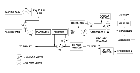
[0033] Fig. 1 is a schematic of a reformed alcohol
power system which utilizes onboard storage of reformate
gases;
[0034] Fig. 2 is a schematic of a reformed alcohol
power system suitable for vehicular applications;
[0035] Fig. 3 is fragmentary cross-section of a flame
jet ignition system used in the reformed alcohol power
system;
[0036] Fig. 4 is a schematic of a reformed alcohol
power system which utilizes jet ignition suitable for
vehicular applications;
[0037] Fig. 5 is a schematic of the reformer used in
the ethanol reforming activity study in Example 7;
CA 02654795 2008-12-08
WO 2007/147008 15 PCT/US2007/071131
[0038] Fig. 6 is a graphical depiction of predicted NOX
emissions for gasoline, hydrogen, ethanol and ethanol
reformate internal combustion engine power systems at a high
load condition as simulated in Example 11;
[0039] Fig. 7 is a graphical depiction of predicted
exhaust temperatures for an ethanol reformate internal
combustion engine power system as simulated in Example 11;
and
[0040] Fig. 8 is a graphical depiction comparing the
predicted peak engine efficiency of an ethanol reformate
internal combustion engine power system with that of
hydrogen, ethanol and gasoline power systems as simulated in
Example 11.
DESCRIPTION OF THE PREFERRED EMBODIMENTS
[0041] In accordance with the present invention,
improved alcohol reforming processes and reformed alcohol
power systems utilizing those processes have been devised.
The alcohol reforming processes preferably utilize a
thermally conductive reforming catalyst that allows
efficient, low-temperature reforming of an alcohol fuel to
produce a reformate gas mixture comprising hydrogen. The
present invention makes possible the efficient utilization of
alcohol fuels in an internal combustion engine to generate
electrical or mechanical power.
[0042] Without being bound to any particular theory,
the increased efficiency of preferred embodiments of the
disclosed invention is thought to occur by at least three
mechanisms. First, the reforming process itself raises the
lower heating value (LHV) of the fuel. In the case of
ethanol, the LHV is raised by about 7%. As the energy
required to drive the reforming reaction is provided at least
in part by waste combustion exhaust, in preferred embodiments
it is not necessary to use the fuel's heating value to drive
CA 02654795 2008-12-08
WO 2007/147008 16 PCT/US2007/071131
the reaction and there is no offset of the increase in the
LHV. Second, the reformate gas mixture is a high octane fuel
which allows high compression ratios to be achieved. Third,
the reformate gas mixture can be combusted under lean
conditions as the reaction products are flammable at
relatively dilute concentrations. The efficiency gains of
the reforming process are verified by combustion modeling as
described in Example 11.
[0043] In one preferred embodiment of the present
invention, hydrogen-containing gas mixtures for burning in an
internal combustion engine are produced by reforming an
alcohol fuel in a manner that allows the thermal energy
demands of the reformer to be satisfied using waste heat
recovered from the engine exhaust. In another preferred
embodiment, low-temperature reforming of an ethanol fuel
produces a product reformate gas mixture comprising hydrogen
and methane, while minimizing deactivation of the reforming
catalyst due to coking. The invention disclosed herein
provides advantages over other technologies used in
exploiting the fuel value of alcohols with high efficiency,
including the conversion of alcohols to hydrogen via
conventional high-temperature reforming processes and
utilization of the hydrogen-containing reformate in fuel
cells of vehicular power systems.
A. The Alcohol Fuel
[0044] A feed gas mixture comprising an alcohol fuel is
contacted with the reforming catalyst in a reforming reaction
zone of the reformer. Preferably, the alcohol fuel comprises
a primary alcohol such as methanol, ethanol and mixtures
thereof. In accordance with an especially preferred
embodiment, the alcohol fuel comprises ethanol. The
preferred reforming catalyst used in the practice of the
present invention is particularly efficient in the low-
CA 02654795 2008-12-08
WO 2007/147008 17 PCT/US2007/071131
temperature reforming of ethanol-containing feed gas mixture,
enabling this environmentally and economically attractive
fuel to be utilized efficiently in a vehicular power system
of relatively modest cost.
[0045] The use of a hydrogen-containing gaseous fuel
produced from ethanol reforming provides an effective means
of starting an ethanol-fueled vehicle at low temperatures,
making it unnecessary to blend ethanol with gasoline, as in
E85 blended fuels. However, reforming catalysts utilized in
embodiments of the present invention are also useful in the
reforming of blended ethanol/gasoline fuels (e.g., E85) as
the sulfur in the gasoline portion of the fuel is not
liberated during the reforming process due to the low
temperatures at which the reforming reaction preferably
occurs. Thus, sulfide poisoning of the copper surfaces of
the catalyst does not appreciably occur.
[0046] In instances where sulfur poisoning does affect
reformer performance, the impact can be minimized by use of
low-sulfur gasoline in the blended fuel mixture. As the
gasoline primarily serves as a starting aid, light-end
alkanes generally very low in sulfur such as isooctane are
preferred. Alternatively or in addition, a bed of high
surface area Raney copper can be included upstream of the
reforming reaction zone to adsorb sulfur and protect the
reforming catalyst and, optionally, to act as a preheater
and/or evaporator. Raney copper is relatively inexpensive
and can easily be replaced as necessary.
[0047] The practice of the present invention allows for
use of alcohol fuels that contain water. Current ethanol
fuels are typically substantially anhydrous and a
considerable portion of the cost of producing fuel-grade
ethanol results from the dehydration step. Moreover,
anhydrous ethanol, unlike ethanol containing water, cannot be
transported in the existing pipeline infrastructure as the
CA 02654795 2008-12-08
WO 2007/147008 18 PCT/US2007/071131
ethanol would ready absorb water present in the pipeline.
Thus, in the practice of the present invention, it is not
necessary to dehydrate the ethanol fuel stock and the cost of
producing the ethanol fuel can be reduced. Further, use of
the present invention in vehicular power systems enables
ethanol to be distributed via the current petroleum pipeline
infrastructure rather than by rail car.
[0048] As noted above, the alcohol fuel used in the
feed mixture fed to the reformer preferably comprises
ethanol. However, alcohol feed mixtures comprising methanol
and methanol-ethanol blends, optionally further containing
water, may also be used. In one preferred embodiment of the
present invention, the alcohol feed mixture comprises an
approximately 1:1 molar mixture of ethanol and water, or
approximately 70% by volume ethanol. In another preferred
embodiment of the present invention, the water content of the
alcohol feed mixture comprising ethanol is reduced to no more
than about 10% by weight, and even more preferably to no more
than about 5% by weight.
B. Low-Temperature Alcohol Reforming
[0049] In accordance with the present invention and
described in further detail below, alcohol fuel in a feed gas
mixture is introduced into the reformer and decomposed into a
hydrogen-containing gas over an alcohol reforming catalyst
(e.g., a copper-plated Raney nickel catalyst) in the
reforming reaction zone. Reaction equation (6) depicts the
reforming of methanol, while reaction equation (7) depicts
the reforming of ethanol in the feed mixture introduced into
the reformer. If the feed mixture containing the alcohol
fuel further contains water (e.g., at least one mole of water
per mole of alcohol), the hydrogen content of the of the
reformate gas mixture may be enriched by reaction of carbon
monoxide with water to form carbon dioxide and hydrogen via
CA 02654795 2008-12-08
WO 2007/147008 19 PCT/US2007/071131
the water-gas shift reaction shown by reaction equations (8)
and (5). The reforming catalysts described below may exhibit
some degree of water-gas shift activity or a separate water-
gas shift catalyst may optionally be employed. The hydrogen-
containing product reformate gas mixture refers to the gas
exiting the reforming reaction zone and following any
optional water-gas shift reaction.
Methanol
without water-gas shift:
CH3OH --> 2H2 + CO (6)
net after water-gas shift:
CH3OH + H20 -> 3H2 + CO2 (8)
Ethanol
without water-gas shift:
CH3CH2OH ~ H2 + CO + CH4 (7)
net after water-gas shift:
CH3CH2OH + H20 ~ CH4 + C02 + 2H2 (5)
C. The Alcohol Reforming Catalyst
[0050] The alcohol reforming reaction is strongly
endothermic and efficient heat transfer to the reforming
reaction zone is desired for good conversion. In accordance
with preferred embodiments of the present invention, mixtures
of copper and other metals, particularly mixtures of copper
and nickel, are used as catalysts for the low-temperature
dehydrogenation (i.e., reforming) of alcohols. Copper-
containing catalysts comprising a thermally conductive metal
supporting structure, for example, a catalyst prepared by
depositing copper onto a nickel sponge supporting structure,
CA 02654795 2008-12-08
WO 2007/147008 20 PCT/US2007/071131
show high activity as catalysts in gas-phase reforming of
primary alcohols such as methanol and ethanol. The catalysts
used in the practice of the present invention are more stable
in and particularly active for the thermal decomposition of
ethanol into hydrogen, methane, carbon monoxide and carbon
dioxide at low temperature.
[0051] In one preferred embodiment of the invention,
the alcohol dehydrogenation or reforming catalyst comprises a
copper-containing active phase or region at the surface of a
metal supporting structure comprising copper and/or one or
more non-copper metals. The catalyst generally comprises at
least about 10% by weight copper, preferably from about 10%
to about 90% by weight copper and more preferably from about
20% to about 45% by weight copper. The catalyst may comprise
a substantially homogeneous structure such as a copper
sponge, a copper-containing monophasic alloy or a
heterogeneous structure having more than one discrete phase.
Thus, the copper-containing active phase may be present at
the surface of the supporting structure as a discrete phase
such as a copper coating or an outer stratum; as a surface
stratum, or as part of a homogeneous catalyst structure. In
the case of a copper-containing active phase comprising a
discrete phase at the surface of the supporting structure,
the metal supporting structure may be totally or partially
covered by the copper-containing active phase. For example,
in a particularly preferred embodiment, the catalyst
comprises a copper-containing active phase at the surface of
a metal sponge supporting structure comprising nickel. Such
catalysts comprise from about 10% to about 80% by weight
copper and more preferably from about 20% to about 45% by
weight copper. The balance of the catalyst preferably
consists of nickel and less than about 10% aluminum or other
metals by weight. Further, in preferred embodiments wherein
the metal supporting structure comprises nickel, it is
CA 02654795 2008-12-08
WO 2007/147008 21 PCT/US2007/071131
important to note that copper and nickel are miscible in all
proportions. Thus, catalysts comprising a copper-containing
active phase at the surface of a nickel supporting structure
may not necessarily have a phase boundary between the copper-
containing active phase and the supporting structure.
[0052] As is common in catalysis, the activity of the
dehydrogenation catalyst is improved by increasing the
surface area. Thus, it is typically preferred for freshly-
prepared catalyst comprising a metal sponge supporting
structure to have a surface area of at least about 10 m2/g as
measured by the Brunauer-Emmett-Teller (BET) method. More
preferably, the catalyst has a BET surface area of from about
m2/g to about 100 m2/g, even more preferably the catalyst
has a BET surface area of from about 25 m2/g to about 100
m2/g, and still more preferably the catalyst has a BET
surface area of from about 30 m2/g to about 80 m2/g.
[0053] In a certain preferred embodiment for the
reforming of ethanol, the surface of the catalyst preferably
contains an amount of nickel atoms which promote the
decarbonylation of aldehydes such as acetaldehyde.
Preferably, the surface comprises from about 5 to about 100
pmol/g of nickel as measured by the method described in
Schmidt, "Surfaces of RaneyO Catalysts," in Catalysis of
Organic Reactions, pp. 45-60 (M.G. Scaros and M.L. Prunier,
eds., Dekker, New York, 1995). More preferably, the surface
nickel concentration is from about 10 pmol/g to about 80
pmol/g, most preferably from about 15 pmol/g to about 75
pmol/g.
[0054] Importantly, the preferred copper-containing
catalysts comprising a metal supporting structure described
herein exhibit superior heat conductivity as compared to
conventional reforming catalysts comprising ceramic supports.
The copper-containing catalysts comprising a metal supporting
structure in accordance with one embodiment of the present
CA 02654795 2008-12-08
WO 2007/147008 22 PCT/US2007/071131
invention preferably exhibit a thermal conductivity at 300K
of at least about 50 W/m*K, more preferably at least about 70
W/m-K and especially at least about 90 W/m*K.
[0055] Suitable metal supporting structures may
comprise a wide variety of structures and compositions.
Preferably, the metal supporting structure comprises a non-
copper metal selected from the group consisting of nickel,
cobalt, zinc, silver, palladium, gold, tin, iron and mixtures
thereof, more preferably selected from the group consisting
of nickel, cobalt, iron and mixtures thereof. Even more
preferably, the metal supporting structure comprises nickel.
Nickel is typically most preferred because, for example: (1)
nickel is relatively inexpensive compared to other suitable
metals such as palladium, silver and cobalt; (2) combinations
of nickel and copper have been shown to promote the
decarbonylation of acetaldehyde to methane and carbon
monoxide; and (3) depositing copper onto a nickel-containing
supporting structure (e.g., by electrochemical displacement
deposition) is typically less difficult relative to
depositing copper onto a supporting structure containing a
significant amount of the other suitable metals. In such a
preferred embodiment, at least about 10% by weight of the
metal supporting structure is non-copper metal. In one
particularly preferred embodiment, at least about 50% (more
preferably at least about 65%, at least about 80%, at least
about 85% or even at least about 90%) by weight of the metal
supporting structure is non-copper metal. In another
embodiment, the supporting structure comprises at least about
10% by weight non-copper metal and at least about 50% (more
preferably from about 60% to about 80%) by weight copper.
The non-copper metal may comprise a single metal or multiple
metals. When the metal supporting structure comprises more
than one metal, it is preferred that at least about 80% by
weight (more preferably at least about 85% by weight, even
CA 02654795 2008-12-08
WO 2007/147008 23 PCT/US2007/071131
more preferably at least about 90% by weight, and still even
more preferably essentially all) of the metals in the
supporting structure are in the form of an alloy.
[0056] In an especially preferred embodiment, the
supporting structure is a metal sponge comprising copper
and/or one or more of the suitable non-copper metals listed
above. As used herein, the term "metal sponge" refers to a
porous form of metal or metal alloy having a BET surface area
of at least about 2 m2/g, preferably at least about 5 m2/g,
and more preferably at least about 10 m2/g. Particularly
preferred metal sponge supporting structures have a BET
surface area of at least about 20 m2/g, more preferably at
least about 35 m2/g, even more preferably at least about 50
m2/g, and still more preferably at least about 70 m2/g. It
has been found in accordance with this invention that a
copper-containing active phase at the surface of a metal
sponge supporting structure results in a material exhibiting
the mechanical strength, high surface area, high thermal
conductivity and density of the sponge supporting structure
combined with the desired catalytic activity of the copper.
Metal sponge supporting structures can be prepared by
techniques generally known to those skilled in the art.
Suitable metal sponges include the material available from
W.R. Grace & Co. (Davison Division, Chattanooga, TN) under
the trademark RANEY as well as materials generally described
in the art as "Raney metals," irrespective of source. Raney
metals may be derived, for example, by leaching aluminum from
an alloy of aluminum and one or more base metals (e.g.,
nickel, cobalt, iron and copper) with caustic soda solution.
Suitable commercially-available nickel sponges include, for
example, RANEY 4200 (characterized by the manufacturer as
having at least 93 wt.% Ni; no greater than 6.5 wt.% Al; no
greater than 0.8 wt.% Fe; an average particle size in the
range of 20-50 pm; a specific gravity of approximately 7; and
CA 02654795 2008-12-08
WO 2007/147008 24 PCT/US2007/071131
a bulk density of 1.8-2.0 kg/l (15-17 lbs/gal) based on a
catalyst slurry weight of 56% solids in water). The metal
supporting structure is preferably substantially free of
unactivated regions and has been washed substantially free of
aluminum oxides. Unreacted aluminum tends to react with
steam under reforming conditions to form aluminum oxides
which can obstruct diffusion and provide acid sites for
ethanol dehydration.
[0057] The copper-containing active phase may be
deposited at the surface of a metal supporting structure
using various techniques well known in the art for depositing
metal onto metal surfaces. These techniques include, for
example, liquid phase methods, such as electrochemical
displacement deposition and electroless plating; and vapor
phase methods such as physical deposition and chemical
deposition. It is important to note that copper is at least
partially miscible with most supporting structure metals of
interest and is completely miscible with nickel. Thus, it
has been found that the copper deposition process may result
in the catalyst having copper, or more particularly a copper-
containing active phase or region at the surface of the
supporting structure as part of a discrete phase such as an
outer stratum or coating, at the surface of the supporting
structure as part of a surface stratum, or copper may migrate
from the surface of the supporting structure into the bulk of
the supporting structure. Without being held to a particular
theory, it is believed that the catalyst surface can move,
sinter or otherwise restructure during the reaction
conditions of the deposition and alcohol reforming processes
resulting in such variations of form in the copper-containing
active phase. Nonetheless, it has been found that the copper
deposition process results in an overall increase in the
copper content of the catalyst with the deposited copper
predominantly present at or near the surface of the freshly
CA 02654795 2008-12-08
WO 2007/147008 25 PCT/US2007/071131
prepared catalyst, which is richer in copper than before
deposition. A particularly preferred alcohol reforming
catalyst comprises a copper-plated Raney nickel sponge, or a
copper-plated, copper-doped Raney nickel sponge. If copper-
doped Raney nickel is employed as the metal supporting
structure, the copper content of the metal sponge is
preferably less than about 10% by weight.
[0058] The alcohol reforming catalyst does not have to
comprise copper coated on a metal supporting structure (i.e.,
there may be no discrete copper-containing active phase
deposited on or coating the surface of the catalyst).
Rather, the copper may be mixed with other metals that
provide desirable properties in a catalyst composition having
a copper-containing active phase at the surface thereof. The
catalyst composition may be substantially homogeneous.
Preferably, such a catalyst is in the form of a copper-
containing metal sponge (e.g., a nickel/copper sponge).
[0059] Suitable alcohol reforming catalyst compositions
for use in the practice of the present invention and methods
and materials for their preparation are described by
Morgenstern et al. in co-assigned U.S. Patent Application
Pub. Nos. US 2004/0137288 Al and US 2002/0019564 Al; U.S.
Patent No. 6,376,708; and in "Low Temperature Reforming of
Ethanol over Copper-Plated Raney Nickel: A New Route to
Sustainable Hydrogen for Transportation," Energy and Fuels,
Vol. 19, No. 4, pp. 1708-1716 (2005), the entire contents of
which are incorporated herein by reference.
[0060] While catalysts comprising a metal sponge
supporting structure having a copper-containing active phase
at the surface as described above are particularly preferred
because of their high thermal conductivity, catalysts
comprising an active phase containing copper or mixture of
copper and nickel at the surface of a non-metallic support
may also be used in the low-temperature reforming of alcohol.
CA 02654795 2008-12-08
WO 2007/147008 26 PCT/US2007/071131
In this context, non-metallic means not in the metallic state
and therefore, for example, not electrically conductive at
ambient temperature. Many oxide supports commonly used for
catalysts, such supports comprising alumina (A1203),
lanthanum oxide (La203), silica (Si02), titania (Ti02),
zirconia (Zr02), siloxane, barium sulfate and mixtures
thereof contain metal atoms, but are thermally and
electrically insulating and, accordingly, are not classified
as metals. Carbon supports have some electrical
conductivity, but can be considered non-metallic for purposes
of this specification. The non-metallic support should be
selected so that it is chemically stable under the conditions
of the reforming reaction and exhibits a high enough surface
area to provide sufficient activity for the reforming
reaction. It is typically preferred that freshly-prepared
catalyst comprising a non-metallic supporting structure have
a surface area of at least about 200 m2/g as measured by the
Brunauer-Emmett-Teller (BET) method. Catalysts prepared with
a non-metallic supporting structure generally comprises at
least about 10% by weight copper, preferably from about 10%
to about 90% by weight copper and more preferably from about
20% to about 45% by weight copper.
[0061] Catalysts comprising copper or mixtures of
copper and nickel on such non-metallic, insulating supports
are active for low-temperature alcohol reforming. As shown
in Example 9, suitable catalysts can be prepared by copper
plating a nickel catalyst on a non-metallic, insulating
support using methods similar to those used for copper
plating metal sponge supports. Example 10 demonstrates that
a copper-nickel catalyst on a non-metallic support (e.g.,
Si02) is active for ethanol reforming above about 200 C, but
at elevated temperatures (e.g., above about 220 C)
selectivity is decreased due to the undesired side reaction
of methanation.
CA 02654795 2008-12-08
WO 2007/147008 27 PCT/US2007/071131
[0062] When the alcohol reforming catalyst is prepared
by electrochemical displacement deposition of copper onto the
surface of the supporting structure (regardless of whether a
metallic supporting structure or a non-metallic, insulating
support is utilized), it is particularly preferable that the
surfaces of the support onto which copper is deposited
contain nickel because nickel has several desirable
characteristics, including: (1) a reduction potential to the
metal which is less than the reduction potential to the metal
of copper; (2) relative stability in the alcohol
dehydrogenation reaction conditions of this invention; (3)
greater mechanical strength and resistance to attrition than
copper; and (4) nickel/copper catalysts promote the
decarbonylation of acetaldehyde to carbon monoxide and
methane.
D. Reformer Design
[0063] The alcohol reforming process of the present
invention generally comprises contacting the feed gas mixture
comprising the alcohol fuel with the reforming catalyst in a
reforming reaction zone of the reformer. As described in
further detail below, the reforming catalyst used in the
practice of the present invention exhibiting high activity
for low-temperature reforming of alcohols is suitable for
incorporation into a compact and thermally efficient heat
exchanger-reformer.
[0064] The reforming reaction zone preferably comprises
a continuous flow system configured to ensure low back-
pressure and efficient heat transfer for initiating and
sustaining the endothermic reforming reaction. Reformer
designs to achieve efficient heat transfer are well known and
described, for example, by Buswell et al. in U.S. Patent No.
3,522,019 and Autenrieth et al. in U.S. Patent Nos. 5,935,277
and 5,928,614. These patents describe catalytic alcohol
CA 02654795 2008-12-08
WO 2007/147008 28 PCT/US2007/071131
reforming reactors in which heat is supplied to the reforming
reaction zone by indirect heat exchange with a heat source
through a heat-conducting wall. Heat sources for heating the
reforming reaction zone include exhaust gases from the
partial oxidation of a portion of the alcohol being reformed
or from a separate combustion reaction using the alcohol or
another fuel source. As described below, a particularly
preferred embodiment of the present invention employs exhaust
gas effluent discharged from a combustion chamber of a
downstream internal combustion engine in which the reformate
product mixture is burned as the heat source for the
reforming reaction zone by bringing the exhaust gas effluent
into thermal contact with the reforming reaction zone to heat
the reforming catalyst. When exhaust gases are used as the
heat source for heating the reforming reaction zone, the
alcohol feed stream and the exhaust stream are preferably not
mixed. By not mixing the exhaust and reformate streams,
better control over the air:fuel ratio is achieved in the
engine and poisoning byproducts of the thermal and oxidative
decomposition of engine lubricating oil is avoided, but heat
transfer is rendered more difficult than would be the case if
the gases were simply mixed. Therefore, the catalyst and
reformer body are preferably fabricated from materials
possessing high thermal conductivity. For this reason, the
reforming catalysts comprising a copper-containing active
phase at the surface of a metallic sponge supporting
structure described herein are particularly preferred in the
practice of the present invention.
[0065] The heat exchanger functions as an alcohol
reformer into which a stream of the alcohol feed mixture is
fed where it contacts the reforming catalyst and is heated to
reaction temperature by indirect heat transfer to the
reforming reaction zone. The alcohol feed stream may first
be evaporated and at least partially heated to the reforming
CA 02654795 2008-12-08
WO 2007/147008 29 PCT/US2007/071131
reaction temperature in a separate heat exchanger upstream
from the reforming reaction zone. In one embodiment, the
vaporization of the alcohol feed is conducted in an
evaporator heated by coolant circulating through the internal
combustion engine of the reformed alcohol power system.
Although vaporization of the alcohol feed can also be
accomplished in the reformer, the use of a separate
evaporator avoids the risk that non-volatile solutes in the
fuel will deposit on the reforming catalyst. In addition, a
separate evaporator heated with engine coolant supplements
the vehicle's radiator in maintaining the temperature of the
engine coolant.
[0066] In one preferred embodiment, the vaporization of
the alcohol feed to the reformer is conducted in an
evaporator heated by the product reformate gas mixture. The
evaporator may be separate from or integrated in the same
unit as the reformer. In addition to evaporating the fuel,
this serves to cool the reformate gas mixture prior to
introduction into the internal combustion engine. Reducing
the temperature of the reformate gas mixture improves engine
volumetric efficiency and peak power of an internal
combustion engine fed with the cooled reformate by reducing
the amount of air displaced in the cylinder (i.e., combustion
chamber) by the hot gaseous fuel. Optionally, in order to
achieve a more compact design, the alcohol vaporization and
reforming functions may be conducted in a single unit.
[0067] In one preferred embodiment, the reformer is
designed to achieve rapid and efficient heat transfer from
the exhaust of an internal combustion engine to the alcohol
feed mixture, allowing the system to be effectively operated
at lower exhaust temperatures, thereby enabling leaner
combustion in the engine. In addition, the high thermal
conductivity of the preferred metallic reforming catalyst
enables more rapid startup of the reformer.
CA 02654795 2008-12-08
WO 2007/147008 30 PCT/US2007/071131
[0068] Preferably, the heat exchanger-reformer is
constructed so that the thermal pathway by which heat is
transferred to the alcohol feed stream is nearly entirely
metallic. Preferred metals for the construction of the heat
exchange surfaces of the reformer that separate the alcohol
feed stream from exhaust of an internal combustion engine or
other suitable heat exchange fluid are those resistant to
corrosion, compatible with the reforming catalyst and possess
high thermal conductivity. Copper, nickel, and alloys
thereof are especially preferred metals. Because the use of
thin metallic sheets is preferred, the sheets may be
reinforced by wire mesh or other means well known in the art
of heat exchanger design, so that the reformer's structure
can resist deformation and the effects of vibration (e.g., in
vehicular power system applications). Because copper does
not catalyze the formation of soot in the reforming process
of the present invention, components of the reformer exposed
to the reforming reaction zone are preferably constructed of
materials that contain a copper-rich surface. Likewise, it
is also preferred that components upstream of the reformer
that contact the alcohol fuel at elevated temperature, (e.g.,
components of the evaporator or preheater) be constructed
having a copper-rich surface. A copper-rich surface can be
achieved by using copper-rich alloys such as MONEL as the
construction material or by plating metals, for example
steel, with copper. A process for producing a system
component with a copper surface by copper plating is
described in Example 1.
[0069] Optionally, a bed of water-gas shift catalyst
may be provided downstream of the reforming reaction zone.
The water-gas shift bed is preferably not in thermal contact
with the exhaust gas effluent used to heat the reforming
reaction zone since the exit temperature of the reformate is
typically adequate to conduct the water-gas shift reaction.
CA 02654795 2008-12-08
WO 2007/147008 31 PCT/US2007/071131
Such catalysts are well known in the art and compact water-
gas shift catalytic units suitable for incorporation in
vehicular reformers have been described by P. Gray and C.
Jaffray in "Fuel Cells for Automotive Applications," R.
Thring Ed. Wiley, New York, 2004, pp. 61-73 and by B.J.
Bowers, J.L. Zhao, D. Dattatraya and M. Ruffo in SAE Special
Publication 1965 (Applications of Fuel Cells in Vehicles),
2005, pp. 41-46.
[0070] Incorporation of a water-gas shift catalyst bed
is not necessary if anhydrous alcohol is used as the fuel,
nor is it necessary if the reformer is not used onboard a
vehicle. For vehicular applications, however, the use of a
water-gas shift catalyst bed causes carbon monoxide in the
reformate to be reduced, which may serve to reduce carbon
monoxide emissions from the vehicle. However, because the
water-gas shift reaction is exothermic, it reduces the lower
heating value of the reformate (e.g., from 317 to 307
kcal/mol for ethanol). In addition, the water-gas shift bed
adds cost and weight to the vehicle. For these reasons,
operation without the water-gas shift bed is generally
preferred, except in applications where minimizing carbon
monoxide is a concern.
[0071] The heat exchanger-reformer is preferably
insulated in order to minimize loss of heat to the
environment. This enables the reforming reaction zone to be
sufficiently heated using lower temperature exhaust gases
from an internal combustion engine of the reformed alcohol
power system. The temperature of the reforming catalyst and
alcohol feed stream is preferably regulated by metering the
flow of exhaust gases through the reformer by providing two
exhaust pathways, one through the reformer and one bypassing
it. In engine configurations that utilize exhaust gas
recirculation (EGR), it is preferred to use the cooled
exhaust gas stream exiting the reformer as the recirculated
CA 02654795 2008-12-08
WO 2007/147008 32 PCT/US2007/071131
gas rather than the exhaust stream which bypasses the
reformer. This design allows for increased volumetric
efficiency and is more effective in reducing NOX and
improving engine thermodynamic efficiency.
[0072] It should be understood that although the
alcohol fuel reforming processes and reformer designs
disclosed herein have particular application in reformed
alcohol power systems onboard vehicles, the reforming
processes and reformers may also advantageously be used in
stationary applications as well as applications independent
of power generation, (e.g., in production of reformate fuel).
E. Incorporation of Preferred Catalysts into the Reformer
[0073] The metal supporting structure (e.g., metal
sponge support), non-metallic or ceramic supports and the
alcohol reforming catalyst having the copper-containing
active phase at the surface thereof may be in the form of a
powder for packed or fixed bed reformer applications.
Alternatively, a fixed bed reformer may utilize a copper-
containing catalyst comprising a metal supporting structure
or non-metallic support in the form of a larger size pellet.
Examples of such shaped supporting structures include the
nickel sponge pellets described in European Patent
Application Publication No. EP 0 648 534 Al and U.S. Patent
No. 6,284,703, the disclosures of which are incorporated
herein by reference. Nickel sponge pellets, particularly for
use as fixed bed catalysts, are available commercially, for
example, from W.R. Grace & Co. (Chattanooga, TN) and Degussa-
Huls Corp. (Ridgefield Park, NJ). Still further, the alcohol
reforming catalyst may be used in the form of a monolith
produced by incorporating the catalyst onto the surface of a
suitable substrate (e.g., the surface of a non-porous sheet
or foil or foraminous honeycomb substrate). Generally,
catalyst in the form of pellets and monoliths are preferred
CA 02654795 2008-12-08
WO 2007/147008 33 PcT/US2007/071131
to minimize back-pressure in the reformer. Further,
monolithic catalysts may be more stable against mechanical
degradation caused by vibration (e.g., in a vehicular power
system application) and/or chemical attack in the alcohol
reforming reaction medium.
[0074] It is important to note that when the catalyst
of the invention is used in the form of a pellet or monolith,
it is contemplated that only a portion of the pellet or
monolith may comprise a metal sponge or non-metallic support
for supporting the copper-containing active phase. That is,
the alcohol reforming catalyst may comprise a non-porous
substrate to provide strength and shape to a fixed bed or
monolithic catalyst while still providing one or more porous
(e.g., metal sponge) regions having a BET surface area of
preferably at least about 10 m2/g for supporting the copper-
containing active phase. Suitable non-porous materials for
use as fixed bed or monolithic substrates generally may
include any material that is thermally and chemically stable
under copper plating and reforming conditions. Although non-
metal substrates may be used, metal substrates such as
nickel, stainless steel, copper, cobalt, zinc, silver,
palladium, gold, tin, iron and mixtures thereof are typically
more preferred. Unactivated aluminum and aluminum alloys are
preferably avoided in the substrate as they react with
ethanol and steam at the reforming temperature.
[0075] When the metal sponge support is in the form of
a powder, the preferred average particle size of the metal
sponge is at least about 0.1 pm, preferably from about 0.5 to
about 100 pm, more preferably from about 15 to about 100 pm,
even more preferably from about 15 to about 75 pm, and still
even more preferably from about 20 to about 65 pm. When the
catalyst is in the form of a pellet or a monolith, the
dimensions of the pellet or the monolithic substrate upon
which the copper-containing active phase is incorporated, as
CA 02654795 2008-12-08
WO 2007/147008 34 PCT/US2007/071131
well as the size of any foramenal openings in monolithic
structures, may vary as needed in accordance with the design
of the reformer as understood by those skilled in the art.
[0076] As shown in Example 2 below, a dry, copper-
plated Raney nickel reforming catalyst in the form of a
powder can be prepared such that it packs at a density of at
least about 1.8 g/cm3. The high packing density of such a
powder catalyst renders it suitable for use in an onboard
fixed bed reformer in vehicular power system applications.
Because the metal structure is hard, attrition is not a
significant problem as might arise in the case of catalysts
supported on alumina and other non-metallic or ceramic
supports. Reforming catalyst in the form of pellets and
other shaped catalyst are also suitable for fixed bed
reformer applications, but typically exhibit lower packing
densities and therefore may require a larger reformer.
Generally, selection of a particular reforming catalyst
system and the attendant consequences with respect to
reformer design will be apparent to those skilled in the art
and can be modified accordingly to meet the objectives of a
particular application.
[0077] To quantify the efficiency of a vehicle running
on ethanol (or other) fuels, it is conventional to express
the efficiency as the power produced divided by the lower
heating value of the fuel. In the case of ethanol, the lower
heating value is 1235.5 kJ/mol as shown in the reaction
equation below.
CH3CH2OH (1) + 3 02 --> 2C02 + 3H20 (g)
AHf = -1235.5 kJ/Mole
[0078] The reformer can be scaled by assuming that the
engine mechanical power out is 35% of the lower heating value
of the ethanol fuel. The 35% figure is reasonable in light
CA 02654795 2008-12-08
WO 2007/147008 35 PCT/US2007/071131
of the predicted peak efficiency of a reformate system as
shown in Fig. 8 and described in Example 11 below.
[0079] The following calculations illustrate
determining the scale required for an onboard fixed or packed
bed reformer using a powdered reforming catalyst such as the
catalyst prepared in Example 2. Consider, for example, a 100
kW vehicle powered by an internal combustion engine running
on a low-temperature ethanol reformate mixture produced in
accordance with the present invention and comprising
hydrogen, methane and carbon monoxide.
[0080] The fuel required at peak power is 13.9 mol/min
(639 g/min) as determined from the following equation:
EtOH_ flow(mol) ,~1235.5 ~ *35%=100 ~ *60 sec
min mol sec min
[0081] As described by Morgenstern et al. in "Low
Temperature Reforming of Ethanol over Copper-Plated Raney
Nickel: A New Route to Sustainable Hydrogen for
Transportation," Energy and Fuels, Vol. 19, No. 4, pp. 1708-
1716 (2005) and shown in Fig. 5a of that publication, 2.5 g
of this type of powdered catalyst completely reforms 0.1
ml/min of 70% ethanol (0.060 g ethanol/min) at 270 C with
negligible backpressure. The catalyst for those experiments
was contained in a 0.375 in. (9.5 mm) internal diameter tube.
The cross-sectional area of the inside of the tube is 0.7
cm2, thus height of the catalyst bed is approximately 2 cm.
[0082] The same Morgenstern et al. publication
indicates that the activation energy for ethanol reforming
over copper-plated Raney nickel is 120 kJ/mole. For design
purposes, a maximum operating temperature for the catalyst of
350 C might be assumed, which would increase the activity of
the catalyst 30-fold over operation of the catalyst at 270 C.
The minimum exhaust temperature for an engine running on
CA 02654795 2008-12-08
WO 2007/147008 36 PCT/US2007/071131
reformed methanol is reported as 350 C in Fig. 10 of JSAE
Review, 1981, 4, 7-13, authored by T. Hirota. Thus, 2.5 g of
catalyst could completely reform 30 x 0.06 = 1.84 g
ethanol/min. To provide adequate catalyst for a 100 kW
engine at a reforming temperature of 350 C requires 869 g of
catalyst in accordance with the following equation:
Catalyst_required =2'5 g catalyst* 639 g ethanoUmin = 869 g catalyst
1.84 g ethanoUmin
[0083] A 869 g quantity of the powdered catalyst
occupies 483 cm3. If the bed height is 5 cm, in order to
minimize backpressure, a disk-shaped reformer packed with a
fixed bed of powdered reforming catalyst 11 cm in diameter
and 5 cm high is adequate for a vehicle with a 100 kW. Such
a reformer may be constructed simply by first feeding a feed
mixture comprising ethanol and optionally water to a heat
exchanger where it is heated to reforming temperature and
then feeding the heated ethanol stream to a packed bed of
copper-plated Raney nickel. The ethanol stream is preferably
vaporized in the heat exchanger utilizing heat from engine
coolant. In the heat exchanger-reformer, the feed mixture
may be heated to reforming temperature utilizing heat from
the exhaust of an internal combustion engine. The exhaust
also supplies the heat required for the endothermic reforming
reaction. Preferably, in a fixed bed reformer embodiment,
the catalyst and heat exchanger are integrated by packing
catalyst into an insulated container equipped with tubes
through which exhaust passes, supplying heat to the reforming
catalyst and the ethanol stream. Integration of the heat
exchanger and catalyst improves thermal response time.
Performance is improved particularly when the vehicle must
accelerate quickly after sitting at idle when the heat
available from the engine exhaust is relatively low.
CA 02654795 2008-12-08
WO 2007/147008 37 PCT/US2007/071131
[0084] In an embodiment where the alcohol reforming
reaction is conducted in a fixed or packed bed reformer
containing a powdered copper-containing catalyst as described
above, measures may be taken to minimize back-pressure by,
for example, adding an inert solid diluent to the reforming
catalyst bed to separate the catalyst particles and maintain
spaces between them. The diluent is preferably a material
free of acid sites which can catalyze dehydration of ethanol
to ethylene and which is thermally stable under the alcohol
reforming conditions. Silicon carbide and activated carbon
which has not been acid-activated are examples of preferred
diluents. Alternatively, back-pressure can be minimized by
using a copper-containing catalyst comprising a metal sponge
supporting structure in the form of pellets, rather than
powders as described herein. In a further alternative
preferred embodiment, the catalyst may be used in the form of
a monolith produced by incorporating the alcohol reforming
catalyst onto the surface of a suitable non-porous or
foraminous substrate in order to minimize back-pressure
within the reforming reactor.
[0085] In one preferred embodiment, the reforming
catalyst is present as a layer or film of copper-plated metal
sponge catalyst on one side of a non-porous foil or sheet
substrate. The sheet is used to form the reforming reaction
zone within the heat exchanger-reformer by techniques well
known in the art, with the catalyst side in contact with the
flow of the alcohol feed stream. Thus, the sheet coated with
a film of the copper-plated metal sponge catalyst may be
incorporated into plate-and-frame or spiral-wound heat
exchanger designs. Alternatively, the sheets may be formed
into tubes for use in a shell-and-tube heat exchanger
reformer design. The latter is particularly preferred for
alcohol reforming vehicular power applications, because it is
compact and thermally efficient.
CA 02654795 2008-12-08
WO 2007/147008 38 PCT/US2007/071131
[0086] Sheet or foil substrates having a copper-
containing Raney catalyst thereon may be produced by
depositing, typically by thermal spraying, a layer of a
nickel-aluminum or other suitable Raney alloy onto the
substrate, activating the Raney alloy, and thereafter copper
plating the activated alloy. Preferred Raney alloys for
spray deposition onto sheet substrates include an
approximately 50:50 (wt:wt) alloy of nickel and aluminum.
The sheet substrate should be thermally and chemically stable
under, activation, copper plating and reforming conditions
and may generally comprise nickel, steel, copper or another
metal, although non-metal substrates may be used. In order
to avoid overly rapid cooling and for improved mechanical
strength, the sheet substrate is preferably at least 20 pm
thick. The thickness of the deposited Raney alloy layer or
film is preferably from about 5pm to about 500 pm, more
preferably from about 10 pm to about 150 pm. The sprayed
sheets are preferably handled with minimal bending prior to
activation in order to prevent delamination of the layer of
Raney alloy deposited thereon. The production of supported
metal sponge films is described in U.S. Patent No. 4,024,044;
by Sillitto et al. in Mat. Res. Soc. Proc., Vol. 549, pp. 23-
9 (1999); and by P. Haselgrove and N.J.E. Adkins in Ceramic
Forum International cfi\Ber. DKG 82 (2005) No.11 E43-45.
[0087] The activation of Raney alloys by treatment with
caustic is well known in the art, particularly for powders,
and is readily adapted to activation of structured Raney
alloys. Typically, activation may be achieved by treatment
of the alloy with caustic (e.g., 20% NaOH) for two hours at a
temperature of about 80 C, as described by D. Ostgard et al.
in U.S. Patent Nos. 6,284,703 and 6,573,213. Activation of
Raney alloy on metal sheet or foil substrates is readily
accomplished using similar techniques, as further described
below in Example 5. The exact method of activation is not
CA 02654795 2008-12-08
WO 2007/147008 39 PCT/US2007/071131
critical so long as adequate surface area is developed and
the handling of the sheets is gentle enough to avoid
excessive delamination of the catalytic layer. Once
activated, the sheet or foil substrates are quite flexible
and can readily mechanically manipulated and formed into a
desired shape for reformer applications. Preferably the
activated sheets are protected from air by, for example,
operation under inert atmosphere or submersion in water
before plating the Raney catalyst layer with copper. For
this reason, the Raney alloy film on a sheet or foil
substrate is preferably manipulated into the desired shape
and assembled into the structure of the reformer after copper
plating, and may be performed in ambient air.
[0088] Copper plating of Raney alloys coated on metal
sheet or foil or other suitable substrates is preferably
conducted by methods similar to those known in the art for
Raney metal powders and described in the above-mentioned
publications by Morgenstern et al., including co-assigned
U.S. Patent Application Pub. Nos. US 2004/0137288 Al and US
2002/0019564 Al; U.S. Patent No. 6,376,708; and "Low
Temperature Reforming of Ethanol over Copper-Plated Raney
Nickel: A New Route to Sustainable Hydrogen for
Transportation," Energy and Fuels, Vol. 19, No. 4, pp. 1708-
1716 (2005). Copper plating of Raney alloy coatings or films
on metal sheet or foil substrates is suitably accomplished by
circulating the plating bath over the substrate while
minimizing bending or vibration of the substrate. Example 6
below describes a suitable method for copper plating of an
activated Raney nickel alloy film on a nickel foil substrate
by electrochemical displacement deposition. Preferably, the
plating will utilize sufficient copper to incorporate from
about 2% to about 70% by weight copper into or on the
activated Raney layer, more preferably from about 10% to
CA 02654795 2008-12-08
WO 2007/147008 40 PCT/US2007/071131
about 50% by weight copper, and still more preferably from
about 15% to about 40% by weight copper.
[0089] Typically, some copper plating of the metallic
sheet or foil substrate will also normally occur, unless the
exposed side of the substrate comprises essentially pure
copper, which is acceptable. Copper plating of the surface
of the sheet or foil substrate, which is predominantly
plating of copper onto copper after the first layer of copper
is deposited, is kinetically easier and faster than plating
of nickel in the interior of the Raney metal film.
Penetration of copper into the interior of the Raney metal
film during plating is hindered by diffusion and by the fact
that the Raney metal (e.g., nickel) surface is likely
oxidized during plating.
[0090] Deposition of copper on the exposed side of a
metal sheet or foil substrate opposite the Raney catalyst
coating or film may be substantially reduced or eliminated by
reversibly passivating the exposed side of the substrate
prior to copper plating. For example, an insulating layer
may be applied onto the exposed side of the substrate and
then stripped from the substrate after the copper plating
procedure has been completed. In one embodiment, an
insulating layer comprising an acrylic polymer is spray-
applied to the exposed side of the Raney metal coated
substrate and then removed after copper plating, for example,
by immersion in a heated bath of xylenes. Example 8 below
describes copper plating of an activated Raney nickel alloy
film on a nickel foil substrate after first passivating the
exposed side of the substrate with an insulating layer.
Passivating the exposed side of the substrate prior to copper
plating not only conserves copper, but by inhibiting copper
from depositing on the exposed side of the substrate is
believed to enhance penetration and diffusion of copper from
the plating bath into the porous structure of the Raney metal
CA 02654795 2008-12-08
WO 2007/147008 41 PCT/US2007/071131
film on the opposite side of the substrate rather than being
predominantly deposited on the surface of the Raney metal
layer. Moreover, by causing copper to more deeply penetrate
into the Raney metal structure, it is believed that this
technique of reversibly passivating the exposed side of the
sheet or foil substrate may also enhance the adhesion the
copper-plated Raney active layer to the substrate surface and
provide a more mechanically robust catalyst structure.
[0091] Methods for coating monoliths (e.g., the surface
of a non-porous sheet or foil or foraminous honeycomb
substrate) with a non-metallic, insulating material to serve
as a support for a copper-containing catalytic active phase
of the alcohol reforming catalyst are well-known in the art.
A typical method, used for the preparation of automotive
exhaust catalysts, includes providing an alumina washcoat to
provide a layer of non-metallic or ceramic support on the
surface of a ceramic monolith (e.g., honeycomb) as described
by R.M. Heck and R.J. Ferrauto in Encyclopedia of Catalysis,
vol. 1, I.T. Horvath ed., Wiley, New York, pp. 517-60 (2003).
Processes for depositing and incorporating metals such as
nickel and copper onto such washcoated substrates to produce
the alcohol reforming catalyst in the form of a monolith are
widely known by those skilled in the art. While less
preferred due to their generally lower thermal conductivity,
non-metallic, insulator supported alcohol reforming catalysts
have the advantage of being readily incorporated into
reformers using these well-known commercial techniques.
F. Reformer Operating Conditions
[0092] The temperature of the catalyst and the product
alcohol reformate gas mixture or stream may be varied
depending on the activity required of the catalyst at any
point in time. Preferably, however, the reforming
temperature is greater than about 200 C (below which
CA 02654795 2008-12-08
WO 2007/147008 42 PCT/US2007/071131
reforming may be incomplete) and less than about 400 C, since
temperatures above this may require more expensive materials
of construction. More preferably, the reforming temperature
is from about 220 C to about 350 C. In the case of alcohol
reforming catalysts comprising a copper-containing active
phase at the surface of a non-metallic supporting structure,
the reforming temperature is preferably from about 200 C to
about 220 C in order to inhibit undesired methanation and
maintain selectivity. The temperature of the gas mixture
within the reforming reaction zone and the catalyst within
the reforming reaction zone are typically approximately the
same.
[0093] It is preferable to operate the reformer below
about 3 atmospheres gauge pressure, primarily because
designing the reformer for high pressure operation entails
the use of more expensive or heavier materials of
construction (e.g., for the shell and thicker, less thermally
conductive sheets of metal coated with alcohol reforming
catalyst). The exit pressure from the reformer is preferably
sufficient to allow for controlled mixing of the reformate
gas with air or other oxygen-containing gas in the
preparation of the intake gas (e.g., fuel-air) mixture for
introduction into the combustion chamber of an internal
combustion engine.
[0094] In embodiments where the feed gas mixture
introduced into the reforming reaction zone of the reformer
comprises ethanol, it is preferred that the reforming process
proceed according to the low-temperature reaction pathway
shown in reaction equations (7) and (5) (after optional
water-gas shift if water is present in the ethanol feed).
That is, by maintaining the reforming temperature within the
preferred range, decomposition of ethanol according to the
pathway of reaction equation (1), which is dominant in high-
temperature steam-reforming systems, does not appreciably
CA 02654795 2008-12-08
WO 2007/147008 43 PcT/US2007/071131
occur. Thus, it is preferred that the product reformate gas
mixture produced comprise hydrogen, methane and a carbon
oxide component selected from the group consisting of carbon
monoxide, carbon dioxide and mixtures thereof. Preferably,
the methane and carbon oxide components are present in
approximately equimolar amounts in the product reformate gas
mixture. Molar ratios of methane to the carbon oxide
component of from about 0.9 to about 1.25 are approximately
equimolar. Moreover, undesired methanation is preferably
minimized. An important advantage of the preferred reforming
catalyst comprising a copper-containing active phase at the
surface of a nickel sponge supporting structure is that
methanation is negligible under the preferred operating
conditions of the reformer at reforming temperatures of up to
about 400 C.
[0095] When the alcohol fuel in the feed gas mixture
introduced into the reforming reaction zone comprises
ethanol, it is also preferred that the rate of methane
production in the product reformate gas mixture be at least
about 50% of the ethanol feed rate on a molar basis (i.e., at
least about 50% conversion of ethanol to methane is
achieved). More preferably, at least about 60% conversion of
ethanol to methane is achieved, even more preferably at least
about 70% conversion, at least about 80% conversion, at least
about 90% conversion, and still more preferably at least
about 95% of ethanol in the feed gas mixture is converted to
methane in the reformate gas on a molar basis. The product
reformate gas mixture preferably comprises not more than
about 10 mole% acetaldehyde and not more than about 20 mole%
ethanol, more preferably, not more than about 5 mole%
acetaldehyde and not more than about 15 mole% ethanol. For
catalysts containing a copper-containing active phase at the
surface of a metal supporting structure, kinetics are
described by Morgenstern et al. in "Low Temperature Reforming
CA 02654795 2008-12-08
WO 2007/147008 44 PCT/US2007/071131
of Ethanol over Copper-Plated Raney Nickel: A New Route to
Sustainable Hydrogen for Transportation," Energy and Fuels,
Vol. 19, No. 4, pp. 1708-1716 (2005) as being a function of
ethanol feed rate, catalyst loading, and temperature such
that reformer conditions can be readily determined and
selected based on power system requirements to produce a
product reformate gas mixture of the desired composition.
Similarly, these parameters can be adjusted accordingly in
the case of other reforming catalysts comprising a copper-
containing active phase at the surface of a non-metallic
supporting structure to produce a product reformate gas
mixture of the desired composition.
[0096] In another embodiment of the present invention,
an alcohol fuel is reformed in a multi-stage reforming
process. This concept is particularly suited for stationary
applications for the production of hydrogen-containing fuels
by reforming of alcohols. In a first low-temperature stage
of the process, the ethanol-containing fuel is introduced
into a first reforming reaction zone and contacted with a
reforming catalyst as described above comprising copper at
the surface of a thermally conductive metal supporting
structure at a reforming temperature below about 400 C,
preferably from about 220 C to about 350 C, to produce a
partially reformed gas mixture comprising hydrogen and
methane in accordance with reaction equations (7) and (5)
(after optional water-gas shift if water is present in the
ethanol feed). The partially reformed gas mixture from the
first reforming reaction zone is then introduced into a
second reforming reaction zone and contacted with a reforming
catalyst to reform methane to hydrogen and carbon monoxide
and produce a reformate gas mixture preferably substantially
free of methane. Typically, the second reforming reaction
zone of the reforming process is a conventional steam
reforming stage in accordance with reaction equation (9) and
CA 02654795 2008-12-08
WO 2007/147008 45 PCT/US2007/071131
operated at a temperature higher than the temperature
maintained in the first reforming stage.
CH4 + H20 -> 3H2 + CO (9)
Catalytic steam reforming of methane and other hydrocarbons
is well-known in the art and is typically conducted over
nickel-containing catalysts. The reaction is highly
endothermic and high temperatures, generally at least about
700 C, are required in order to obtain acceptable conversions
in the second reforming reaction zone. High-temperature
steam reforming of hydrocarbons as occurs in the second
reforming stage is discussed by D.E. Ridler and M.V. Twigg in
Catalyst Handbook, 2nd ed., M.V. Twigg ed. Manson Publishing,
London, pp. 225-282 (1996), the disclosure of which is
incorporated herein by reference.
[0097] The overall reforming reaction in the first and
second reforming reaction zones is shown in reaction equation
(1).
[0098] Optionally, a water-gas shift reaction can be
employed in such an embodiment resulting in the overall
reforming reaction depicted in reaction equation (10).
CH3CH2OH + 3H20 -> 2C02 + 6H2 (10)
This multi-stage reforming embodiment reduces coking that
occurs in high-temperature ethanol steam reformers that
operate according to reaction equation (1). The coking is
believed to be caused by dehydration of ethanol to ethylene
that rapidly forms coke. Without being bound to any
particular theory, it is believed that if the ethanol fuel is
first reformed to carbon monoxide, methane and hydrogen at
low temperature according to reaction equation (7) and the
methane further reformed to carbon monoxide and hydrogen in a
CA 02654795 2008-12-08
WO 2007/147008 46 PCT/US2007/071131
subsequent, higher temperature steam reforming stage
according to reaction equation (9), coking can be avoided or
substantially reduced. In such a multi-stage ethanol
reforming process, high-temperature reformate mixture (or
portion thereof) exiting the second reforming reaction zone
may be used to supply heat to the low-temperature reformer
containing the first reforming reaction zone.
G. Reformed Alcohol Power System Design
[0099] The present invention achieves efficient
utilization of an alcohol fuel in an internal combustion
engine system to produce mechanical and/or electrical power.
The internal combustion engine system may produce torque to
drive a vehicle or in combination with a generator produce
electric power. In one embodiment, a feed gas mixture
comprising the alcohol fuel is contacted with an alcohol
reforming catalyst as described above (e.g., comprising
copper at the surface of a thermally conductive metal
supporting structure) in a reforming reaction zone of a
reformer and reformed to produce a hydrogen-containing
product reformate gas mixture. An intake gas mixture
comprising the resulting hydrogen-containing reformate gas
mixture and an oxygen-containing gas (e.g., air), optionally
along with non-reformed alcohol fuel, is introduced into a
combustion chamber (i.e., cylinder) of an internal combustion
engine and combusted to generate power and produce an exhaust
gas mixture. An exhaust gas effluent comprising the exhaust
gas mixture is discharged from the combustion chamber of the
engine and brought into thermal contact with the reforming
reaction zone to heat the reforming catalyst therein to a
temperature sufficient to support the alcohol reforming
reaction and produce the product reformate gas mixture.
CA 02654795 2008-12-08
WO 2007/147008 47 PCT/US2007/071131
[00100] In comparison with an engine fueled with non-
reformed, liquid ethanol, internal combustion engines fueled
by the hydrogen-containing gas mixture produced by reforming
of the alcohol fuel in accordance with the present invention
can be operated with increased compression ratios and leaner
air:fuel ratios. Higher compression ratios can be employed
because hydrogen, carbon monoxide and methane are far less
prone to knock than gasoline. Thus, the engine can be
operated more efficiently.
[00101] The reformed alcohol power systems of the
present invention does not include a fuel cell and the
hydrogen-containing reformate gas mixture (after optional
water-gas shift if water is present in the alcohol feed) is
instead combined with air or other oxygen-containing gas to
form the intake gas mixture combusted in the internal
combustion engine. In order to maximize the attendant
benefits of the hydrogen-containing reformate gas mixture as
a fuel for the internal combustion engine, it is preferred
that at least about 80% of the hydrogen and other components
(e.g., methane in the case of ethanol reforming) obtained in
the product reformate gas mixture be introduced into the
internal combustion engine. More preferably, at least 90%,
at least 95%, or substantially all of the hydrogen and other
components obtained in the product reformate gas mixture is
utilized as fuel in the internal combustion engine.
[00102] Because the power system in accordance with the
present invention does not include a fuel cell, it is
possible to optionally operate the engine with conventional
gasoline instead of an alcohol fuel. This allows vehicles to
be fueled by alcohol, where available, and to be fueled with
gasoline if an alcohol fueling station is not available.
Further, while, as discussed below, the use of reformed
alcohols, particularly reformed ethanol, is preferred to the
use of liquid, non-reformed alcohols as the primary motor
CA 02654795 2008-12-08
WO 2007/147008 48 PCT/US2007/071131
fuel due to improved efficiency and cold start, operation
using liquid alcohol fuels in a flex-fuel engine utilizing
the Miller or Atkinson cycle may be desired. Use of liquid
alcohol fuel such as ethanol, without reforming, offer
slightly improved volumetric efficiencies compared to the use
of reformed alcohol fuels.
[00103] Flexible fuel operation is achieved by use of
the Miller or Atkinson cycle, which enables an internal
combustion engine of a power system which utilizes a four-
stroke power cycle to be operated at reduced compression
ratios when gasoline fuel is used and increased compression
ratios when an alcohol reformate gas mixture or liquid
alcohol fuel is used. The Miller and Atkinson cycles are
generally characterized in that they enable the expansion
ratio to exceed the compression ratio thereby increasing
power system efficiency.
[00104] In order to be able to operate on gasoline,
reformed alcohol or liquid alcohol fuels, it is necessary to
avoid compression ratios that lead to knock. This can be
done by operating in the Miller or Atkinson cycle with
adjustments to the timing of the intake valve. In the Miller
or Atkinson cycle, the intake valve is left in its open
position past the end of the intake stroke (bottom dead
center in crank angle space). As the piston begins the
compression stroke, fuel air mixture is pushed out of the
cylinder into the intake manifold through the intake valve.
Compression of the gas begins only after the intake valve
closes. Thus, when operating on gasoline, it is preferable
to close the intake valve at a point that ensures the knock
limit is not exceeded. Typically in gasoline blends,
especially blends containing 90% by volume gasoline (e.g.,
E10 or gasoline not diluted by ethanol) the compression ratio
should not be higher than about 10, although this depends on
the octane rating of the gasoline.
CA 02654795 2008-12-08
WO 2007/147008 49 PCT/US2007/071131
[00105] When reformed alcohol, especially reformed
ethanol is used as a fuel, the intake valve is preferably
closed earlier, enabling a higher compression ratio to be
used. A preferred value is above about 12 and, more
preferably, at about 14 (used by Hirota et al. for reformed
methanol).
[00106] When alcohol, especially blends containing at
least 85% by volume ethanol (e.g., E85 or E100) is used as a
fuel, the intake valve is preferably closed earlier, enabling
a higher compression ratio to be used. A preferred value is
above about 12 and, more preferably, at about 14 (used by
Hirota et al. for reformed methanol).
[00107] The expansion ratio is not affected by the valve
timing adjustment, thus the system will benefit from the
improved efficiencies associated with high expansion ratio
when utilizing gasoline and reformed alcohol fuels. However,
the increased compression ratio used with reformed alcohol
fuel increases the amount of fuel in the cylinder and thus
the power.
[00108] Preferably, the power system of the present
invention is able to control the length of time the intake
valve remains in the open position in response to the type of
fuel sent to the combustion chamber(s). Fuel sensors (e.g.,
polarity or electrochemical sensors) located anywhere along
the pathway of fuel from the storage tank to the combustion
chamber can by used to determine the type of fuel being sent
to the combustion chambers and can be of the type and design
common to flex fuel vehicles presently in operation.
[00109] All internal combustion engines operate with
highest efficiency in an optimum range of load and engine
speed. Engines operating on hydrogen-rich feeds have
relatively wide optima, as shown, for example, in the above-
mentioned publications authored by T. Hirota and by Keller et
al. In order to obtain the highest efficiency over the
CA 02654795 2008-12-08
WO 2007/147008 50 PCT/US2007/071131
complete drive cycle, reformed alcohol power systems in
accordance with this invention for vehicular and other
applications preferably incorporate technologies well known
in the art for maintaining engine speed and load in the
optimal range over as much of the drive cycle as possible.
[00110] Thus, in one preferred mode of operation, the
vehicle drive train comprises a continuously variable
transmission or "CVT." Continuously variable transmissions
allow, within limits, the ratio of the wheel or drive shaft
rotational speed to the engine speed to vary continuously.
CVTs improve fuel economy by eliminating torque converter
losses associated with conventional transmissions and by
allowing the engine to run at its most efficient speed. A
particularly preferred embodiment utilizes the Anderson
variable transmission, described in U.S. Patent Nos.
6,575,856 and 6,955,620, the entire contents of which are
incorporated herein by reference.
[00111] Other techniques, well known in the art, can be
used to maintain the internal combustion engine at optimum
load per cylinder throughout the drive cycle. One method is
to idle some of the cylinders when power demand is low.
Another is the use of a hybrid electric drive train, of which
there are a number of commercial examples, such as the TOYOTA
PRIUS or FORD ESCAPE. One or more electric motors are used
to supply supplemental torque when power demand is high. The
motors can also be used to generate power via regenerative
braking. When power demand is low, excess engine power is
used to charge the battery by driving an alternator.
[00112] Combustion of the gases produced by alcohol
reforming in accordance with embodiments of the present
invention, specifically CH4, CO and H2, counteracts the cold
start problem that afflicts systems that combust non-reformed
alcohol fuel directly. In one preferred embodiment of the
present invention, a supply of reformate gas is maintained
CA 02654795 2008-12-08
WO 2007/147008 51 PCT/US2007/071131
onboard the vehicle. This onboard supply can be used to fuel
the engine at startup and during subsequent operation until
the reformer has attained operating temperature and can be
used for transient periods of high fuel demand such as
acceleration. The fuel is preferably hydrogen or hydrogen-
containing alcohol reformate because combustion of these
fuels produces a clean exhaust, which is not expected to
require a catalytic converter.
[00113] An onboard supply of reformate gas may be
provided by increasing the size and pressure rating of the
reformer and providing inlet and outlet valves such that a
quantity of reformate gas is stored within the reformer when
the vehicle is shut down. In such a system, a slow
methanation reaction may occur in the reformer resulting in
the production of a mixture of CH4 and C02. This
configuration also increases the size and weight of the
reformer, thereby increasing cost and complicating the task
of ensuring efficient thermal contact between the exhaust gas
stream and the catalyst bed of the reformer.
[00114] It is therefore preferable to provide an onboard
reformate storage tank and a small compressor that can be
used to shunt a small fraction of the reformate to the
storage tank as shown in Fig. 1. The reformate should
preferably be stored close to ambient temperature in order to
increase the capacity of the storage tank and to improve
engine volumetric efficiency resulting from delivery of the
reformate to the engine at a higher density. In addition,
avoiding excessive temperatures in the storage tank prevents
the creation of excess pressure that might cause the vessel
to rupture. For these reasons, the storage tank is
preferably located in a region of the vehicle where it is
exposed to ambient air and maintained at a lower temperature
such as outside the engine compartment. The storage tank may
CA 02654795 2008-12-08
WO 2007/147008 52 PCT/US2007/071131
be equipped with a reliable pressure relief device as an
additional safety feature.
[00115] As an alternative to onboard storage of
reformate, the catalyst bed in the reformer can be preheated
to the temperature necessary to maintain the reforming
reaction by electric or thermal-chemical source.
[00116] Fig. 2 is a schematic of one embodiment of a
reformed alcohol power system in accordance with the present
invention suitable for use in vehicular applications. In a
preferred embodiment, a turbocharger or supercharger is
employed to pressurize the mixture of air and reformed
alcohol fed to the engine and the fuel-air mixture is passed
through an intercooler (referred to as Intercooler 2 in Fig.
2) to reduce its temperature prior to introduction into the
cylinder of the engine. It is preferred to compress the
mixture, rather than just air as is conventional for liquid
fuels, because this enables the reformer to be operated close
to atmospheric pressure and improves fuel-air mixing. The
use of compressed fuel-air mixtures as a feed to the engine
increases the maximum power available from the engine. It is
further preferred to use a separate intercooler (Intercooler
1 in Fig. 2) to cool the alcohol reformate prior to blending
with air. Cooling of the alcohol reformate can be
accomplished more efficiently than cooling of a reformate-air
mixture owing to the higher temperature of the reformate. In
a preferred embodiment of the present invention, the alcohol
feed is used to cool the alcohol reformate in Intercooler 1.
[00117] As discussed above, the intake valve is
preferably left open until shortly after the beginning of the
compression stroke in the cylinder, which has the effect of
pushing some of the fuel-air charge back into the intake
manifold. This mode of operation, known as the Miller cycle,
is preferred for two reasons. First, gaseous fuels displace
volume that might otherwise be occupied by air if a liquid
CA 02654795 2008-12-08
WO 2007/147008 53 PCT/US2007/071131
fuel were employed. When maximum power is required from the
engine, the usual practice is to employ a roughly
stoichiometric air:fuel ratio. When using gaseous fuels such
as an alcohol reformate, pressurization of the charge is
required in order to obtain peak power similar to that of a
liquid-fueled engine. The second reason is that, without the
intercooler, the fuel-air charge would be hot due to the heat
introduced during reforming of the alcohol and turbocharging
of the air. The hot charge is more prone to detonate
prematurely. Operation without the turbocharger (the
Atkinson cycle) or without delayed closing of the intake
valve are further embodiments of the invention, but the
former sacrifices some peak power and the latter some
efficiency in comparison to the Miller cycle. Both the
Miller and the Atkinson cycle improve efficiency at part load
by eliminating throttling losses.
[00118] An important advantage of the Miller and
Atkinson cycles is that they enable the engine to be run on
conventional gasoline without knock. Typical gasoline
formulations will knock at compression ratios above 10, but
it is preferable to operate ethanol reformate and liquid
ethanol fuel at higher compression ratios in order to improve
efficiency. Thus, when gasoline is being used to fuel the
engine, it is preferred to leave the intake valve open longer
after the beginning of the compression stroke in order to
reduce the compression ratio to a suitable value for
gasoline.
[00119] In a preferred embodiment, a power system
configured to operate on liquid alcohol fuel, reformed
alcohol fuel and mixtures thereof is provided. The system
would include a reformer smaller in size than a reformer used
in a system which generated power from reformed alcohol
alone. In embodiments where ethanol is the reformed fuel,
the system would typically run on reformed ethanol at startup
CA 02654795 2008-12-08
WO 2007/147008 54 PCT/US2007/071131
and at points in the drive cycle near about 1500 rpm. When
higher power is required from the engine, the system would
run on non-reformed fuel. This system design has several
advantages over other designs, namely the decreased capital
cost of the smaller reformer, decreased time for the reformer
to achieve operating temperatures sufficient to maintain the
reforming reaction and the ability to achieve high volumetric
efficiency without the need to turbocharge. Improved
volumetric efficiency also allows for a smaller size of the
internal combustion engine. For example, in accordance with
one preferred embodiment of the present invention wherein the
intake gas mixture comprises ethanol reformate comprising
hydrogen and methane and the non-reformed ethanol fuel, the
molar ratio of ethanol to methane in the intake gas mixture
is at least about 10 and in another preferred embodiment, the
molar ratio of ethanol to methane in the intake gas mixture
is less than about 0.4.
[00120] In one preferred embodiment, the engine is
spark-ignited. The use of spark ignition provides more
consistent and reliable combustion, particularly when using
gasoline as a fuel, and allows engine timing to be adjusted
as the fuel is varied.
[00121] In a preferred embodiment, jet ignition is
utilized in order to enable reliable ignition and complete
combustion to be achieved using reformed ethanol fuel at lean
air:fuel ratios. Such systems are well known in the art as a
technique to extend the engine's lean stable operating limit
and are discussed by Heywood in Internal Combustion Engine
Fundamentals (McGraw Hill, New York, 1988) on pages 447-50.
Ignition occurs in a prechamber cavity, containing the spark
source, which is in fluid communication with the rest of the
cylinder (i.e., to the main combustion chamber) through an
orifice or nozzle. A particularly preferred embodiment
CA 02654795 2008-12-08
WO 2007/147008 55 PCT/US2007/071131
enriches the prechamber with alcohol reformate when the
engine is operating on a reformed alcohol fuel.
[00122] An example of a flame jet ignition system
wherein the prechamber gas mixture and combustion chamber
intake gas mixture are both supplied from portions of the
product reformate gas mixture is illustrated in Fig. 3. The
product reformate gas mixture is produced upstream of the
ignition system by contacting a feed gas mixture comprising
an alcohol fuel with a reforming catalyst (e.g., catalysts as
described above comprising a copper-containing active phase
at the surface of a ceramic or non-metallic support,
preferably a metal sponge supporting structure) in a reformer
reaction zone.
[00123] With reference to Fig. 3, an auxiliary intake
passage 1 connects the exit of the reformer to an auxiliary
intake valve 2, which is connected to the prechamber 3
equipped with a spark plug 4. The prechamber 3 is in fluid
communication with the main combustion chamber 5. During
intake, the auxiliary intake valve 2 is opened, causing an
intake gas mixture comprising oxygen and a portion of the
product reformate gas mixture to pass through the prechamber
3 and into the main chamber 5. This results in purging of
the prechamber. The product reformate gas mixture may,
alternatively, be fed to the main chamber 5 through intake
valve 7. The auxiliary valve 2 (and intake valve 7 if used)
is closed before the beginning of the compression stroke.
During compression, the lean alcohol reformate gas mixture in
the main combustion chamber 5 of the cylinder is forced into
the prechamber and preferably bringing the prechamber
composition to a composition slightly rich of stoichiometry
at the time of the spark discharge. The flame which develops
in the prechamber 3 after discharge causes a rise in pressure
that, in turn, forces one or more hydrogen-rich flame jets
CA 02654795 2008-12-08
WO 2007/147008 56 PCT/US2007/071131
into the main chamber 5, ensuring rapid and complete
combustion of the intake gas mixture therein.
[00124] In an especially preferred embodiment, the
prechamber gas mixture comprises ethanol reformate containing
hydrogen and methane and the intake gas mixture comprises
oxygen and fuel. A variety of fuels may be selected for use
in the intake gas mixture, including, for example, alcohol
reformate compositions, non-reformed liquid alcohol, liquid
alcohol/water blends (e.g., E10 or E85) and gasoline. In
embodiments where the fuel used in the intake gas mixture is
different from the prechamber gas mixture (i.e., is other
than ethanol reformate), it is preferred that the intake gas
mixture be delivered to the main chamber 5 through intake
valve 7 rather than auxiliary intake valve 2.
[00125] Fueling of the jet ignition system with liquid
fuels, such as ethanol and gasoline, is also feasible, but in
that case, the liquid fuel is preferably supplied to the
prechamber via a fuel injector.
[00126] Fig. 4 depicts a reformed alcohol power system
utilizing jet ignition. A water-gas shift bed is not
included as in the power system depicted in Fig. 2 as it is
assumed the vehicle operates on ethanol with a low water
content and there is no turbocharger. The flow of reformate
to the jet and the intake manifold is controlled with
variable valves 9, 10. The remainder of the system operates
in accordance with the system shown in Fig. 2 and described
herein.
[00127] As jet ignition enables lean combustion of
alcohols, it is particularly useful in a power system
configured to operate on both liquid alcohol fuel and a
reformed alcohol fuel and which employ a reformer smaller in
size than a reformer of a system which generates power from
reformed alcohol alone as described above. K. Wakai et al.
in Effect of Small Hydrogen Jet Flame on Augmentation of Lean
CA 02654795 2008-12-08
WO 2007/147008 57 PCT/US2007/071131
Combustion, SAE Paper 931943, 1993, demonstrate the use of
hydrogen jet ignition to maintain reliable combustion of
methanol under very lean conditions, for example, with a cp
equal to about 0.5. Hydrogen jets with a cp equal to 0.5, 1.0
and 2.0 were generated by igniting the H2-02 mixture in a
prechamber with a volume 1% of the main chamber volume. K.
Wakai et al. report that the hydrogen jet igniter reliably
ignites the very lean mixture and results in faster and more
complete combustion.
[00128] To achieve the same effect with an ethanol
reformate system, a larger prechamber is required due to the
significantly slower flame speed. Honda's Compound Vortex
Controlled Combustion (CVCC) engine used jet ignition with
larger prechambers and a relatively fuel-rich gasoline-air
mixture. T. Date et al. report the use of prechambers with a
volume of 4%, 7.3% and 16% of the total combustion volume in
Research and Development of the Honda CVCC Engine, SAE paper
740605, 1974. According to the authors the optimum ratio of
fuel to the prechamber to total fuel is 40% at idle and 25%
at 50 mph.
[00129] Thus, reformate supplied through the prechamber
is preferably from about 5 to about 20% of the fuel value at
high load. This results in improved volumetric efficiency as
compared to a power system where all of the fuel is reformed.
At lower loads the reformer can supply a higher faction of
the fuel.
[00130] The remainder of the fuel input would be
composed of a liquid fuel, preferably an alcohol and most
preferably ethanol. The liquid fuel is introduced through
the intake manifold with use of a carburetor rather than fuel
injection, as this enables use of the Atkinson cycle and
provides the flexibility to use either gasoline or ethanol as
liquid fuel.
CA 02654795 2008-12-08
WO 2007/147008 58 PCT/US2007/071131
[00131] In accordance with one preferred embodiment,
reformed ethanol, in addition to being used for jet ignition,
is added to the intake manifold. According to E.J. Tully et
al. in Lean-Burn Characteristics of a Gasoline Engine
Enriched with Hydrogen from a Plamatron Fuel Reformer, SAE
paper 2003-01-630, 2003 and 2. Ivanic et al. in Effect of
Hydrogen Enhancement on Efficiency and NOX Emissions of Lean
and EGR-Diluted Mixtures in an SI Engine, SAE paper 2005-01-
0253, 2005, mixtures of gasoline and 15-30% reformed gasoline
(C0, H2, and N2) with normal ignition are known to burn
leaner with higher efficiency than ordinary gasoline.
Similar efficiency gains are expected in the case of ethanol.
One skilled in the art can experimentally optimize the split
between reformed ethanol to the jet and to the intake
manifold over the speed and load map.
[00132] In another preferred embodiment, the fuel-air
mixture is subjected to stratified charge combustion. In a
further preferred embodiment, the fuel-air mixture is not
spark ignited, but rather ignition is achieved by the use of
Homogeneous Charge Compression Ignition (HCCI) as described,
for example, by A.O. zur Loye et al. in U.S. Patent No.
6,915,776. HCCI is well known in the art as a method for
utilizing well-mixed fuel-air mixtures, such as those
produced in the practice of the present invention. High
thermal efficiency can be achieved by the use of HCCI with
proper control of operational variables such as equivalence
ratio, as set forth by zur Loye et al.
H. Fuel System Operation
1. Normal Operation
[00133] Referring again to Fig. 2, a preferred
configuration in accordance with the present invention is
illustrated. If the ambient temperature is high enough for
adequate volatilization of the alcohol fuel (e.g., above
CA 02654795 2008-12-08
WO 2007/147008 59 PCT/US2007/071131
about 15 C for ethanol), then the power system is started
similarly as in a conventional vehicle. Valves V3, V4, V5,
V7 and V8 are closed and valve V6 is fully open. If the
vehicle is operating on alcohol fuel, then valve V1 is
closed, valve V2 is open, and alcohol is supplied to the
carburetor using the liquid fuel pump. If gasoline is to be
used at startup, valve V1 is open and valve V2 is closed, and
gasoline is supplied to the carburetor using the liquid fuel
pump. The power system of Fig. 2 can be designed without a
source of gasoline without departing from the scope of the
present invention.
[00134] Regardless of whether alcohol fuel or gasoline
is used at startup, the exhaust from the engine is forced
through the reformer to heat it to the desired operating
temperature as quickly as possible. When the operating
temperature is reached, variable valves V6 and V7 are
adjusted accordingly in order to regulate the flow of exhaust
gases through the reformer body and maintain the desired
operating temperature in the reforming reaction zone
contained therein.
2. Startup at low ambient temperatures
[00135] When the ambient temperature is too low to
reliably start the engine, then the engine is started with
valves V1, V2, V3, V4, V7 and V8 closed and valve V6 fully
open. Gaseous fuel from the gaseous fuel tank is metered
using valve V5, blended with air and used as the starting
fuel. Shortly after the engine has been started, liquid
fuel (gasoline or alcohol) is supplied to the carburetor,
valve V5 is closed, and normal startup is resumed.
CA 02654795 2008-12-08
WO 2007/147008 60 PCT/US2007/071131
3. Steady State Operation on Reformed Alcohol Fuel
[00136] Once the reformer has reached operating
temperature, valve V3 is opened (valve V4 remains closed) and
alcohol is pumped into the reformer using the reformer pump
(not shown). When the pressure in the reformer reaches the
design value, the reformed alcohol gas mixture valve V4 is
partially opened and, from then on, variable valve V4 is used
to meter the reformate gas into the fuel intake system. At
this time, the liquid fuel pump is shut off, valves V1 and V2
are closed, and the reformer pump is controlled to maintain
the desired pressure in the reformer. As shown in Fig. 2,
the reformed alcohol gas mixture is passed through a water
gas-shift stage containing a suitable catalyst (WGS bed)
before the reformate gas is introduced into the fuel intake
system. The optional water-gas shift catalyst bed may be
omitted if desired, for example when the alcohol fuel
comprises anhydrous ethanol.
[00137] Optionally, during steady state operation, some
of the reformed gas may be used to recharge the gaseous fuel
tank using the compressor and opening valve V8. If operated
in this manner, it is preferable to use an alcohol fuel
containing less than one mole of water per mole of alcohol to
avoid condensation of water in the gaseous fuel tank.
4. Idle Operation on Reformed Alcohol Fuel
[00138] As can be see from Fig. 7, predicted engine
exhaust temperatures at low idle are less than those at
greater power demand. Thus it may be desirable for the
engine exhaust to bypass thermal contact with the reformer at
idle conditions so as to not cool the catalyst bed.
According to one preferred embodiment, V6 is closed and V7
opened during idle conditions such that the exhaust by-passes
the reformer.
CA 02654795 2008-12-08
WO 2007/147008 61 PCT/US2007/071131
5. Steady State Operation on Gasoline
[00139] If the alcohol fuel tank is empty, the system
continues to operate fueled by gasoline supplied by the
gasoline pump to the carburetor.
[00140] It will be appreciated by one skilled in the art
that the present invention can be used in conjunction with a
wide range of engine and drive train technology beyond that
which has been described. For example, the use of rotary
engines, direct injection of alcohol or gasoline into the
cylinders, the induction of swirl in the cylinder to improve
speed of combustion, and the use of other engine cycles, such
as the Westport cycle are all feasible using alcohols
reformed in accordance with the present invention.
[00141] While it is preferred that the reformed alcohol
system design and operation of the fuel system be performed
with alcohol reforming catalysts described herein, such
designs and operations are not limited to such catalysts and
are compatible with other reforming catalysts.
[00142] The following examples are simply intended to
further illustrate and explain the present invention. This
invention, therefore, should not be limited to any of the
details in these examples.
Example 1 - Copper Plating of a Stainless Steel Preheater for
Ethanol Reforming
[00143] This Example describes copper plating of a
preheater used to heat an ethanol stream upstream of the
catalyst bed in order to suppress side reactions catalyzed by
the steel. The preheater consists of a vertically-mounted
length of 316 stainless steel tubing (1/2" o.d. (1.27 cm),
3/8" i.d. (0.95 cm)) heated with a coil heater. In
operation, ethanol is pumped through a tube (1/8" o.d. (0.32
cm)) also wrapped around the heater. The ethanol then passes
upward through the preheater. The heater is controlled with
CA 02654795 2008-12-08
WO 2007/147008 62 PCT/US2007/071131
a temperature controller which senses the temperature of gas
exiting the preheater.
[00144] The copper plating was applied to a 316 SS
preheater tube (100 g) using a peristaltic pump to circulate
a simple copper-plating bath through it. The bath was
composed of CuC12 (5.37 g) acidified with concentrated HC1
(15 g) in deionized water (135 g) in order to remove oxides
and allow the entire interior surface of the tube to be
plated. The bath contained a total of 2 g of copper metal.
The mixture was circulated through the bath for two hours.
The blue color faded and was replaced by deep green, likely
due to nickel displaced by copper. A rough, but uniform
copper deposit was seen inside the tube.
Example 2 - Scaled Up Copper Plating of Nickel Sponge with
Drying
[00145] This example demonstrates that copper plating of
a nickel sponge support by electrochemical displacement
deposition can be effectively conducted at high solids
loading. The use of high solids loading reduces the cost of
catalyst production by improving the productivity of the
process and reducing the volume of wastewater. In order to
further reduce cost, the amount of copper used in the second
(acidic) step of the plating process has been decreased from
25% to 10% of the nickel sponge substrate mass.
[00146] The amount of NaOH used was reduced from 1.5
equivalents to 1.0 equivalents (based on the amount copper in
the plating bath). Enough gluconic acid buffer was used to
supply the protons required to disproportionate the Cu20
formed in the first step:
Cu20 + 2H+ _> Cu2+ + Cu + H20
CA 02654795 2008-12-08
WO 2007/147008 63 PCT/US2007/071131
[00147] This example further shows that the copper-
plated nickel sponge catalyst can be dried and safely handled
thereafter. When dry, the catalyst does not exhibit
pyrophoric behavior. Use of a dust mask in handling dry
catalyst is recommended.
[00148] Raney nickel powder (673 g, grade 4200) was
weighed out by Archimedes' method in a 4-liter beaker using a
density factor of 1.16. In the first step of the plating
process, CuSO4=5H2O (661 g, 25% by weight copper with respect
to substrate; mixture of material from VWR and Mallinckrodt)
and Versene 100 (2911 g, 1.1 equiv. of Na4EDTA, Dow via
Spectrum) were combined and stirred to dissolve the copper
sulfate. The supernatant was decanted from the Raney nickel
and the copper-EDTA mixture added. Next, 50% NaOH (212 g,
1.0 equiv.) was added dropwise over 38 minutes while stirring
with an overhead stirrer. The pH rose from 9.1 to 11.6. At
the end of the addition, the slurry occupied 3.4 liters for a
substrate weight:volume ratio of 19.8%.
[00149] The deep blue supernatant was decanted and the
beaker wrapped with heating tape. In the second step of the
plating process, 50% gluconic acid (1038 g, 1.0 equiv with
respect to copper added in the first step, Spectrum) and
water (1 liter), both heated, were added to the beaker and
stirring initiated. A solution of CuSO4=5H2O (264 g, 10% by
weight copper with respect to substrate) in water (1 liter)
was added dropwise over 82 minutes with continuous stirring
and heating. The pH fell from 3.3 to 2.4. The initial and
final temperatures were 56 C and 70 C, respectively. The
final volume was 3.4 liters, matching that in the first step.
[00150] The blue-green supernatant was decanted and the
catalyst rinsed twice with deionized water. The rinse was
conducted by adding water to a slurry volume of 3.4 liters,
stirring briefly, and then settling the catalyst and
decanting the supernatant. The second rinse had a pH of 4.0
CA 02654795 2008-12-08
WO 2007/147008 64 PCT/US2007/071131
and was clear. The catalyst was initially a bright copper
color, but partially darkened to a copper brown color during
the decantation.
[00151] The catalyst was then transferred to an 800 ml
beaker where it occupied 350 ml. It was dried overnight at
120 C under 24" Hg (610 mm Hg) vacuum with nitrogen purge.
The copper-colored catalyst was transferred in air to a
bottle. Some heating occurred and a few sparks were
observed. 679 g of catalyst were recovered.
[00152] In order to allow the catalyst surface to be
passivated by oxygen in a controlled way without overheating,
the bottle of catalyst was evacuated, backfilled with argon
and loosely capped. The catalyst bottle was placed in a
beaker of water to cool the bottle as air slowly entered the
catalyst bottle. The catalyst color dulled slightly. After
half an hour, the bottle was removed from the water bath.
The cap was left loose for another hour, but no heating was
observed, so the bottle was capped for storage. No heating
or further change in catalyst color was observed when the
catalyst was stored in air at room temperature.
[00153] Elemental analysis of the dried catalyst by
Inductively Coupled Plasma Mass Spectrometry (ICP-MS)
determined that its composition to be: 67.8% Ni, 29.6% Cu,
and 2.7% Al. The dried catalyst packed at a density of 1.8
g / cm3 .
Example 3 - Ethanol Reforming with and without a Copper
Plated Preheater
[00154] Anhydrous ethanol was reformed over dry copper-
plated Raney nickel (2.5 g) produced by the process of
Example 2 at 280 C at a feed rate of 0.07 ml/min. The
preheater used upstream of the catalyst bed was not copper
plated. Coking caused backpressure to develop in the
CA 02654795 2008-12-08
WO 2007/147008 65 PCT/US2007/071131
preheater, forcing the experiment to be terminated after 36
hours.
[00155] The plugged preheater was replaced by a copper-
plated stainless steel tube prepared by the process of
Example 1. Anhydrous ethanol was reformed for 118 hours with
the same catalyst at a temperature of 280 C at a flow rate of
0.07 ml/min. The catalyst was not replaced. Coking was not
observed. Pressure remained below 3 psig (144 mm Hg gauge)
Ethanol breakthrough rose from 4% to 16% over the first 75
hours and then leveled off.
Example 4 - E85 Reforming with a Copper Plated Preheater
[00156] The experiment in Example 3 was conducted but
the feed was changed to a simulated E85 fuel. The E85
simulant was a mixture of 85% absolute ethanol and 15% n-
pentane on a volume basis (8.2% pentane on a molar basis).
Pentane passed through the reformer without reaction. No new
peaks were seen by gas chromatography and the exit
concentration of pentane was 8%, indicating that pentane was
not consumed. The experiment was continued to a total run
time of 125 hours (200 total hours with 75 hours being the
copper-plated run of Example 3). Pressure remained below 3
psig (155 mm Hg gauge) and slow deactivation continued with
ethanol breakthrough reaching about 21% at the end of the
run.
Example 5 - Activation of a Raney Nickel Alloy Film
[00157] This example describes the activation of a film
of Raney nickel alloy (50% aluminum, 50% nickel) coated on a
38 pm nickel foil (CERAM, Stoke-on-Trent, Great Britain).
The nominal loading of Raney nickel alloy on the foil was
0.070 g/cm2. The Raney nickel alloy-coated foils were 12 cm
in width and cut to 30-40 cm lengths. The preparation of the
Raney alloy-coated metal foils is described by P. Haselgrove
CA 02654795 2008-12-08
WO 2007/147008 66 PCT/US2007/071131
and N.J.E. Adkins in Ceramic Forum International cfi\Ber. DKG
82 (2005) No.11 E43-45.
[00158] The activation was conducted in a glass
developing tank (7 cm x 27.5 cm in cross section) for thin
layer chromatography. To avoid the necessity of bending the
Raney nickel alloy-coated foil, a piece (31 cm long and 12 cm
wide) was cut in two (17 cm x 12 cm and 14 cm x 12 cm)and the
two pieces placed in the glass developing tank. The initial
weight of the Raney nickel alloy-coated foil was 38.76 g.
The total quantity of Raney alloy on the foil was calculated
to be 26 g. Ice (1100 g) was added to the tank followed by
50% NaOH (400 g). Water (1200 ml) was added to raise the
water level above the top of the film.
[00159] The foil was kept in the tank for six hours
during which the bath warmed to room temperature and hydrogen
evolution was steady. The color of the Raney nickel alloy
film darkened conspicuously. After the six hours lapsed, the
liquid was drained from the tank and replaced by water
(approximately 2 liters at 85 C) which promoted bubbling
despite the absence of base, followed immediately by the
addition of 50% NaOH (200 g). Gas evolution increased
dramatically after base addition, but there was no foaming.
Gradually, gas evolution decreased. After 20 minutes,
additional 50% NaOH (600 g) was added to the tank. This led
to an increase in hydrogen evolution similar to that which
occurred during the first base addition. An hour after the
first base addition, hydrogen evolution had slowed to a low
rate. The films were flexible.
[00160] The glass tank was then drained and the
activated foils rinsed twice in the tank with deionized (DI)
water. The smaller of the two pieces of foil was rinsed
extensively under a deionized water tap and cut into two
pieces. One piece was stored in a glass jar under water and
the other dried overnight at 120 C under 24" Hg (610 mm Hg)
CA 02654795 2008-12-08
WO 2007/147008 67 PCT/US2007/071131
vacuum with nitrogen purge. The larger of the original two
pieces of foil was used for copper plating in Example 6.
[00161] Activated catalyst scraped from the foil had the
following normalized metal content as determined by ICP-MS:
90.5% Ni, 9.4% Al and 0.16% Fe. The activation of the Raney
nickel alloy-coated foils and observations are summarized in
Table 1 below.
Table 1
Time (min) Temp ( C) Notes
0 -4 Time zero is the time of addition of
NaOH and water
1 +8 Slow bubbling
2 +11
15 +9
40 +5 Ice melted, bubbling primarily from
bottom of films
60 +5 Bubbling accelerating
105 +7 Bubbling still vigorous
165 +11 Bubble-rich zone about 4 cm from
bottom of the films
300 +21 Still bubbling, foils still stiff,
alloy surface is dark
360 +20->85 Liquid drained and hot dilute NaOH
added, vigorous H2 evolution,
declining somewhat over time
380 75 600 g of 50% NaOH added, H2
evolution increases
420 58 Bubbling almost over, films are
flexible, tank drained
Example 6 Copper Plating of Activated Raney Nickel Alloy
Film on Nickel Foil
[00162] This example describes the copper plating of the
activated Raney nickel alloy film on nickel foil prepared in
Example 5. The larger piece of the activated foil (17 cm x
12 cm) was rinsed under the deionized water tap and
transferred to a 1 liter beaker. It was then completely
CA 02654795 2008-12-08
WO 2007/147008 68 PCT/US2007/071131
submerged in deionized water to protect it from air and held
overnight.
[00163] In order to avoid damaging the foil, a magnetic
stirrer (Ikamag REO) was used instead of an overhead stirrer.
The stir bar was weakly attracted to the film due to the
ferromagnetism of nickel, but the stirrer had a magnet
sufficiently powerful to keep the stir bar in the center of
the beaker, while the foil was coiled to conform roughly to
the beaker wall with the Raney surface facing inward.
[00164] CuSO4=5H2O (6.21 g, 20% by weight copper with
respect to the activated Raney film as calculated above),
Versene 100 (27.4 g, 1.1 equivalents of Na4EDTA based on
copper in the plating bath) and deionized water (700 ml) were
combined and sparged with nitrogen. The beaker containing
the foil was drained and the copper solution added
immediately. The beaker was topped off with deionized water
(about 200 ml, not nitrogen-sparged) in order to completely
submerge the foil. 2.5N NaOH (15 ml, 1.5 equivalents) was
added dropwise while stirring for 48 minutes. The pH rose
from 11.7 to 12.7. The activated side of the foil acquired a
rich copper color. The blue supernatant was decanted and the
beaker wrapped with heating tape.
[00165] CuSO4=5H2O (7.76 g, 25% by weight copper with
respect to the activated Raney film) was dissolved in water
(100 ml) and added to the dropping funnel. A hot mixture of
50% gluconic acid (37 g, 3 equivalents), 2.5N NaOH (12 ml)
and water (400 ml) was added to cover the foil (about 500
ml). The mixture was nitrogen-sparged. The initial
temperature was 45 C and the initial pH was 3.3. Power was
applied to the heating tape, and the copper solution added
dropwise over 70 minutes while stirring. The solution grew
an increasingly deep green. The final pH was 3.2 and the
final temperature was 71 C. The green supernatant was
decanted and the bright copper-colored foil rinsed and stored
CA 02654795 2008-12-08
WO 2007/147008 69 PCT/US2007/071131
in deionized water. The back (foil) side also was copper-
plated.
[00166] Catalyst scraped from the foil had the following
normalized metal content as determined by ICP-MS: 48.4% Ni,
47.0% Cu, 4.50% Al and 0.11% Fe. Based on elemental analysis
data, the foil comprised about 0.046 g/cm2 of activated
catalyst.
Example 7 - Ethanol Reforming Using Copper-Plated Raney
Nickel Alloy Film on Nickel Foil
[00167] This example describes testing of the copper-
plated Raney nickel alloy film catalyst on nickel foil
prepared in Example 6 for ethanol reforming activity. A
schematic of the reforming apparatus used for activity
testing is shown in Fig. 5 and described by Morgenstern et
al. in "Low Temperature Reforming of Ethanol over Copper-
Plated Raney Nickel: A New Route to Sustainable Hydrogen for
Transportation," Energy and Fuels, Vol. 19, No. 4, pp. 1708-
1716 (2005).
[00168] A rectangle (11 cm x 6 cm, 5.99 g wet) was cut
from the center of the copper-plated foil prepared in Example
6 and the uncoated edges were trimmed off. The rectangle was
coiled tightly lengthwise (i.e., to make a cylinder 6 cm
long) and inserted into the reforming tube having an inside
diameter of 0.375 in. (9.5 mm) of the apparatus with the
catalyst side facing inward. The coil fit easily in the tube
and around the 0.125 in. (3.2 mm) thermocouple located in the
center of the tube. The thermocouple did not extend the full
6 cm, so the open space was partially filled with a 0.125-
inch (3.2 mm) diameter stainless steel rod. The reformer was
connected to the preheater and flushed with nitrogen
overnight.
CA 02654795 2008-12-08
WO 2007/147008 70 PCT/US2007/071131
[00169] The reformer was brought to temperature under
nitrogen flow prior to beginning the ethanol-water feed. A
mixture of 70% ethanol in water (mole H20:mole ethanol = 1.1)
was used as the feed solution and prepared by adding water to
200 proof ethanol (available from Aaper, Shelbyville, KY).
The ethanol-water feed solution was delivered to the reformer
with an Isco 500D syringe pump.
[00170] The catalyst was maintained under substantially
isothermal conditions (within 1 C) by the use of two heaters.
The ethanol-water feed flowed upward through a preheater,
which was controlled to maintain the feed temperature at the
entrance to the catalyst bed at the desired value. A cable
heater, aligned with the catalyst bed, supplied the heat of
reaction and kept the exit temperature equal to the inlet
temperature of the catalyst bed.
[00171] A six-port Valco valve was used to direct
samples of the reformer effluent to the injection port of a
gas chromatograph (Varian 3400 GC) equipped with a thermal
conductivity detector. A 10 ft. x 0.125 in. x 0.085 in.
(3.05 m x 3.2 mm x 2.2 mm) Hayesep D packed column (Alltech)
was used.
[00172] The flowrate and temperature were varied for the
first 30 hours until an operating point of 0.1 ml/min
(corresponding to 1.318 mmoles of ethanol/min) and 320 C was
chosen. Under these conditions, about 10% ethanol remained
unreacted, allowing us to monitor deactivation of the
catalyst. There was evidence of some methanation, likely
catalyzed by the exposed nickel on the side of the foil
opposite the catalyst. In an automotive reformer, the
exposed nickel on the back of the foil would not be in
contact with the ethanol feed mixture (it would be in contact
with the exhaust), so this observation is not a concern.
CA 02654795 2008-12-08
WO 2007/147008 71 PCT/US2007/071131
[00173] After about 100 hours on stream, pressure began
to increase and the experiment was terminated. Prior to this
time, the inlet pressure had been less than 3 psig (155 mm Hg
gauge). The pressure rise was the result of some catalyst
particles detaching from the foil and creating a partial
blockage downstream.
[00174] The yield of the low-temperature reforming
products during the period when the reformer was operated at
320 C with a feed rate of 0.1 ml/min and the pressure below 3
psig are set forth in Table 2 below. Conversion was steady,
indicating that the catalyst was stable.
Table 2: Yield of Low-Temperature Reforming Products During
Ethanol Reforming at 320 C, 0.1 ml/min of 70% Ethanol Feed
Mixture
Hours CH4 CO C02 CH3CHO CH3CH2OH
30 94.6% 53.7% 22.6% 7.9% 6.6%
40 103.5% 53.7% 25.7% 2.4% 6.2%
50 103.4% 46.0% 24.9% 2.6% 10.2%
60 110.0% 39.1% 32.8% 1.8% 7.3%
70 110.5% 39.6% 29.9% 1.6% 8.4%
80 111.6% 31.8% 38.7% 1.4% 7.6%
[00175] Note that methane yields and mass balances based
on methane can exceed 100% due to analytical uncertainties
and the methanation of CO by reaction with hydrogen to
produce methane and water. Note also that the hydrogen yield
is omitted from the Table 2. Although hydrogen was measured
directly in the gas chromatograph, thermal conductivity
detectors exhibit low sensitivity for hydrogen compared to
carbon-containing molecules resulting in more scatter in the
data. Accordingly, hydrogen yield can be calculated more
accurately from the yield of carbon-containing compounds such
as carbon monoxide, carbon dioxide and methane.
CA 02654795 2008-12-08
WO 2007/147008 72 PCT/US2007/071131
Example 8 - Copper Plating of Activated Raney Nickel Alloy
Film on Nickel Foil Utilizing Reversible Passivation of the
Back of the Foil
[00176] Electron microscopy of the copper-plated Raney
nickel alloy film catalyst on nickel foil prepared in Example
6 revealed that copper plated heavily onto the back of the
foil (i.e., on the side opposite the Raney nickel catalyst),
but copper penetrated less than about 10 pm into the Raney
nickel film layer. Nickel can easily be oxidatively removed
from the interior of the Raney nickel film, but copper
plating of the foil surface, which is predominantly plating
of copper onto copper, is faster than plating of the interior
of the Raney nickel film. Penetration of copper plating is
hindered by diffusion and by the fact that the nickel surface
is likely oxidized during plating.
[00177] In this Example, copper plating on the back of
the foil was eliminated by coating it with an insulating
layer of an acrylic polymer. The polymer layer was then
stripped after the copper plating procedure had been
completed. The insulating layer was applied using Sprayon
S00611 Clear Lacquer Electrical Spray, a fast drying,
waterproof insulating component sealer (Diversified Brands,
Cleveland, Ohio, available from distributors such as
Grainger). Sprayon S00611 consists of a proprietary acrylic
polymer in mixed organic solvents, primarily acetone,
toluene, propane, and butane.
[00178] A piece (11 cm x 9cm) of Raney nickel alloy-
coated foil (CERAM, Stoke-on-Trent, Great Britain) activated
in accordance with the procedure in Example 5 was copper
plated using the procedure described below. The activated
foil had been stored under water after activation. The foil
was removed from the water, patted dry with tissues, laid
foil-side-up on a clean tissue, and sprayed with Sprayon
S00611. The foil was then transferred to a bed of thoroughly
soaked tissues in a glass beaker where it was laid down,
CA 02654795 2008-12-08
WO 2007/147008 73 PCT/US2007/071131
again foil side up. The purpose of the tissues was to keep
the Raney nickel side wet and protected from oxidation while
the acrylic film dried on the foil.
[00179] The target copper concentration in the catalyst
phase was 35% by weight with respect to the activated Raney
film. CuSO4=5H2O (6.36 g), Versene 100 (27.6 g, 1.1 equiv.
of Na4EDTA) and deionized water (450 ml) were combined and
added to a beaker equipped with a stir bar and containing the
acrylic polymer-coated, Raney nickel foil. 2.5N NaOH (13 ml,
1.3 equiv.) was added dropwise more quickly than usual so as
to be faster than any deterioration of the acrylic layer.
The NaOH addition was performed over 7 minutes while
stirring. The pH rose from 11.7 to 12.6. The dark blue
supernatant was decanted. The back side of the foil (i.e.,
opposite the activated Raney side) was free of copper
deposition.
[00180] The beaker was wrapped with heating tape and the
decanted liquid replaced with a warm (34 C) mixture of 50%
gluconic acid (9.8 g, 1.0 equivalent with respect to copper
in the first step) and water (500 ml). The pH was 2.4.
Power was applied to the heating tape and stirring initiated
in order to disproportionate the Cu20. The temperature
reached 60 C in ten minutes and was maintained at that level
until the end of this step of the plating experiment.
[00181] Stirring was discontinued after 45 minutes. At
this point, the liquid was nearly colorless, the pH was 2.3
and the temperature was 60 C. The foil was removed from the
beaker, rinsed with deionized water and stored in a beaker
under deionized water. There was no sign of copper plating
on the back of the foil.
[00182] The next day, the water was drained and a small
(approximately 1 cm x 1 cm) sample cut from the foil. The
foil sample was then returned to the beaker and hot (71 C)
xylenes (500 ml) added. Power was applied to the heating
CA 02654795 2008-12-08
WO 2007/147008 74 PCT/US2007/071131
tape and the beaker was stirred for 30 minutes in order to
remove the acrylic polymer layer. The final temperature was
105 C. The xylenes were poured off and the foil rinsed with
deionized water and stored in a glass bottle under deionized
water.
[00183] The catalyst side of the foil was almost black
with only a few faint patches of faint copper color. This
indicates that copper was not predominantly deposited on the
surface of the Raney nickel film, but rather penetrated into
it.
[00184] Another sample (approximately 1 cm x 1 cm) was
obtained and both samples were dried overnight in a vacuum
oven at 120 C under 24" Hg (610 mm Hg) vacuum with nitrogen
purge.
Example 9 - Preparation of a Copper-Nickel Catalyst on a
Silica Support
[00185] The plating method of this Example is similar to
that in Example 2, however the copper addition in the second
step of Example 2 is omitted in order to keep the pH above 2.
This was done to avoid dissolution of silica. All of the
copper was added in the first step, and the second step was
performed at acidic pH to disproportionate copper deposited
in the first step (which is thought to be predominantly in
the form of Cu20) via the following reaction.
Cu20 + 2H+ + Ni -> 2Cu + Ni2+ + H20
[00186] The substrate used was 70% by weight nickel on
silica, reduced and stabilized, from Acros Organics, lot
A013077801. The substrate (40 g) was added to a beaker (1
liter) containing a nitrogen-sparged mixture of CuSO4=5H2O
(33.0 g; 21 wt% Cu with respect to substrate, 30 wt% with
respect to nickel), Versene 100 (145 g; 1.1 equiv. of
CA 02654795 2008-12-08
WO 2007/147008 75 PCT/US2007/071131
Na4EDTA, Dow via Spectrum) and water (300 ml). NaOH (58 ml;
1.1 equiv.; 2.5N) was then added dropwise over 24 minutes
while stirring with an overhead stirrer under a nitrogen
atmosphere. The pH rose from 11.6 to 13.4. The catalyst was
filtered off and rinsed with deionized water. The filtrate
was blue.
[00187] The recovered catalyst was returned to the
beaker which was wrapped with heating tape. A hot solution
of lactic acid (18 g; 1.5 equiv. with respect to copper
added; Aldrich,) in water (300 ml) was added, power was
applied to the heating tape, and the slurry was gently
stirred for 50 minutes under a nitrogen atmosphere. The
initial pH was 2.4 and the initial temperature was 53 C. At
the end of this step, the pH had risen to 6.2, indicating
that the disproportionation had occurred. The final
temperature was 62 C.
[00188] The catalyst was recovered by filtration and
rinsed with deionized water. The filtrate exhibited a strong
nickel green color. The catalyst was dried overnight at
120 C under 24" Hg (609 mm Hg) vacuum with nitrogen purge.
Black catalyst (29.1 g) was recovered. No self-heating was
observed.
Example 10 - Activity of Copper-Nickel on Silica Catalyst
[00189] The catalyst (2.5 g) of Example 9 was used to
test the activity of copper-nickel silica supported catalysts
using the same reforming apparatus used for activity testing
in Example 7 and shown schematically in Fig. 5. A feed (of
0.1 ml/minute) of 70% ethanol and 30% water by volume was
used and the temperature was varied. The catalyst was active
at low temperature for the reforming of ethanol to H2, CO,
and CH4. However, above 220 C, methanation occurred, likely
catalyzed by unplated nickel.
CA 02654795 2008-12-08
WO 2007/147008 76 PCT/US2007/071131
[00190] This example also illustrates the efficacy of
using Monel as a material of construction for the preheater
to suppress coking. A new preheater tube fabricated from
Monel was used during the run. No sign of coking was seen in
the preheater. The backpressure never exceeded 6 psi and was
generally below 4 psi (206 mm Hg) during the run with no sign
of an increase. The run was continued for 194 hours with no
operational difficulty.
[00191] Product distributions, in mol % relative to
ethanol supplied are provided in the Table 3, wherein the
abbreviations "Acet" and "EtOH" represent acetaldehyde and
ethanol, respectively. An Arrhenius plot between 185 C and
210 C provided an activation energy of 16.3 kcal/mol, which
is identical thermodynamic enthalpy for ethanol
dehydrogenation. Thus, with this catalyst loading, ethanol
conversion is thermodynamically limited below about 210 C.
CH3CH2OH (g) , CH3CHO (g) + H2
AHf= +16.27 kcal/mole
Table 3: Product Concentrations of Ethanol Reformed over a
Copper-Nickel Silica Supported Catalyst
Temp ( C) H2 CO CH4 CO2 Acet EtOH
185 42.8% 30.7% 33.9% 1.9% 6.1% 60.6%
190 54.0% 41.2% 45.7% 2.9% 5.3% 49.8%
195 65.8% 51.4% 58.4% 4.3% 4.4% 38.5%
200 77.5% 61.2% 71.3% 6.1% 3.3% 27.4%
205 88.6% 74.2% 90.9% 9.4% 2.5% 10.2%
210 98.6% 74.2% 101.9 16.6% 2.1% 1.6%
0
0
220 69.4% 72.3% 115.4 12.4% 0.0% 0.0%
0
0
225 78.6% 54.2% 117.9 27.9% 0.0% 0.0%
0
0
230 7.6% 0.1% 148.4 51.5% 0.0% 0.0%
0
0
CA 02654795 2008-12-08
WO 2007/147008 77 PCT/US2007/071131
[00192] Between about 220 C and about 230 C, methanation
activity increases rapidly and by 230 C, methanation is
nearly complete, with the overall stoichiometry shown by the
reaction equations below. This corresponds to a shift from
endothermic to exothermic chemistry. As a result, thermal
instability was encountered in this temperature range. As
methanation chemistry began, it tended to heat the catalyst,
further increasing methanation. The temperature controller
compensated by reducing heat input, but temperature
correction was slow and temperature oscillations were
observed.
CH3CH2OH(g) ~ CH4 + CO + H2 AHf = +11.72 kcal/mole
2CH3CH2OH(g) ~ 3CH4 + C02 AHf = -35.66 kcal/mole
[00193] Thus, copper-nickel catalysts on silica appear
to be highly active at low temperature, achieving
thermodynamically-limited conversion, but are prone to
methanation at higher temperatures.
Example 11 - Predicted Engine Performance Generated from
Combustion Modeling
[00194] Efficiency and emissions performance of several
powertrain systems were compared by combustion modeling using
the "GT-POWER" simulation program. Simulated systems include
internal combustion engines spark-ignited with a premixed
charge and fueled by (1) gasoline, (2) hydrogen, (3)
anhydrous ethanol and (4) ethanol reformate generated from
contacting anhydrous ethanol with a reforming catalyst with
copper at the surface of a thermally conductive metal
supporting structure and without a water-gas shift. The
combustion model used a one-dimensional, two zone flame speed
with an equilibrium gas composition. Performance was
evaluated at steady-state.
CA 02654795 2008-12-08
WO 2007/147008 78 PCT/US2007/071131
Optimized Air/Fuel Equivalency Ratio
[00195] The models were run under lean conditions as
engine power can be determine from fuel flow without varying
the air flow and pumping losses associated with throttling
are avoided. The air:fuel equivalence ratios used for the
hydrogen (H2) and ethanol reformate (Ref.) engine simulations
at a range of brake mean effective pressures (BMEP) are shown
in Table 4 below. These lean limits were determined by
increasing the air:fuel ratio in the simulation until the
predicted efficiency became unfavorable or combustion
parameters such as burn time, total mass fraction burned,
etc., became unfavorable.
Table 4: Optimized lean Air/fuel Equivalence Ratios used in
the Simulations
BMEP (bar)
6 H2: 2.20 H2: 2.20 H2: 2.20
Ref: 2.00 Ref: 2.00 Ref: 2.00
4 H2: 2.86 H2: 2.86 H2: 2.86
Ref: 2.00 Ref: 2.00 Ref: 2.00
2 H2: 3.12 H2: 3.12 H2: 3.12
Ref: 2.00 Ref: 2.00 Ref: 2.00
0.5 H2: 3.85
Ref: 2.00
Engine Speed 850 1500 2200 3000
(RPM)
At low load conditions the simulated reformate engine must be
operated with slight throttling. When the reformate engine
is operated unthrottled at low fuel feed rates, dilution of
the fuel with air is quite high. The simulation indicated
that partial throttling at low fuel rates was necessary to
maintain sufficiently rapid combustion.
Optimized Engine Parameters
[00196] Engine parameters used in the simulation were
optimized for each system to achieve maximum efficiency while
meeting NOX emissions standards (CA LEV II 50k, 0.05 g/mile,
14 ppm average over the drive cycle). First, the highest
CA 02654795 2008-12-08
WO 2007/147008 79 PCT/US2007/071131
allowable compression ratio was found by increasing the
compression ratio incrementally until knock was predicted.
Next, the spark timing for maximum brake torque at the
operating points of interest was established. The parameters
were then further optimized for high efficiency and adjusted
to meet NOX emissions standards based on simulated emissions
results for each engine configuration except the reformate
engine. In the case of the reformate engine, previous tests
of lean hydrogen operation in the laboratory suggested that
the air:fuel mixture will be lean enough to produce the
required low levels of NOX of the CA LEV II 50 k emissions
standards.
[00197] The key engine parameters used in the
simulations are shown below in Table 5.
Table 5: Key Engine Parameters used in the Simulation
Compression Throttled? Three-way Boosted?
Ratio rottled? Mixture Catalyst? oosted?
Gasoline ICE 9 Yes Stoichiometric Yes No
Hydrogen ICE 14.5 No Lean Not Yes
(See Table 4) Necessary
Anhydrous
Ethanol ICE 14 Yes Stoichiometric Yes No
Anhydrous
Ethanol 14 Partial Lean Not Yes
Reformate (See Table 4) Necessary
ICE
[00198] Each engine system was optimized to compare
best-case scenarios for each fuel using a port fuel injected
internal combustion engine. Technologies that would have
given across the board improvements such as engine down-
sizing were not considered. The ethanol and reformate
configurations use anhydrous ethanol without a denaturant
such as gasoline. In practice, a denaturant may reduce the
actual compression ratios achieved.
[00199] As shown in Table 5, optimizing each simulated
engine system for predicted high efficiency and predicted low
NOX resulted in various system operating strategies.
CA 02654795 2008-12-08
WO 2007/147008 80 PCT/US2007/071131
Gasoline and ethanol systems were simulated at stoichiometric
air:fuel ratios to allow for three-way catalyst (i.e.
catalytic converter) operation, while hydrogen and reformate
engines were simulated lean at part load conditions to reduce
pumping losses from throttling and were maintained at
air:fuel ratios that rendered a three-way catalyst
unnecessary to meet emissions standards. Simulated hydrogen
and reformate engines were boosted to provide a better power
output during lean operation. Other adjustments were made in
the simulation to ensure smooth predicted engine operation,
including a 25% increase in spark size for the reformate
engine.
Results
[00200] The results of the simulations are shown in
Figs. 6 and 7. Fig. 6 depicts the NOX emissions predictions
of the simulation for the gasoline, hydrogen and ethanol
systems. The reformate system data was generated from
previously tested cases of lean hydrogen operation. As can
be seen from Fig. 6 and as designed for in the simulation,
NOX emissions for each configuration are maintained below CA
LEV II 50 k emissions standards, i.e., below about 14 ppm.
In practice, NOX emissions would be expected to be higher,
perhaps by an order of magnitude, than the simulation due to
the two-zone flame assumption of the simulation. The high
load case where BMEP is equal to 6 bar and where emissions
are the highest is shown in Fig. 6. The Figure indicates
that, over a drive cycle, predicted average NOX emissions are
expected to be below the limit of 14 ppm.
[00201] Predicted exhaust temperatures for the reformate
system are shown in Fig. 7. Reformate engine exhaust
temperature is predicted to remain high, i.e. at least about
400 C, at all conditions except idle. Accordingly, thermal
contact between the exhaust gas and the reformer should be
CA 02654795 2008-12-08
WO 2007/147008 81 PCT/US2007/071131
sufficient to maintain reformer operating temperatures of at
least about 300 C.
[00202] Calculated peak efficiencies for the engine
systems are shown in Fig. 8. As can be seen from the Figure,
the anhydrous ethanol system results in predicted efficiency
improvements over the gasoline system. The anhydrous ethanol
reformate system further increases those benefits largely due
to the 7% increase in LHV of the fuel as a result of
reforming.
[00203] The design power output for each engine was
assumed to be 108 kW, however the majority of drive-cycle
power is less than 50 kW, with a maximum load of 6 bar and
maximum speed of 6000 RPM. The efficiencies shown in Fig. 8
are best-case efficiencies. The engine will not be at peak
efficiency at all points of the drive cycle. The energy
required for boosting was not taken into account in the
hydrogen and reformate cases however this should not result
in a large efficiency drop if the engine is properly
turbocharged.
[00204] In view of the above, it will be seen that the
several objects of the invention are achieved and other
advantageous results attained.
[00205] As various changes could be made in the above
methods and constructions without departing from the scope of
the invention, it is intended that all matter contained in
the above description and shown in the accompanying drawings
shall be interpreted as illustrative and not in a limiting
sense.
[00206] When introducing elements of the present
invention or the preferred embodiments(s) thereof, the
articles "a", "an", "the" and "said" are intended to mean
CA 02654795 2008-12-08
WO 2007/147008 82 PCT/US2007/071131
that there are one or more of the elements. The terms
"comprising", "including", "containing" and "having" are
intended to be inclusive and mean that there may be
additional elements other than the listed elements.