Note: Descriptions are shown in the official language in which they were submitted.
CA 02655117 2008-12-10
WO 2007/146774 PCT/US2007/070712
Title: ONE TOUCH DATA ACQUISITION
Inventors: SCOTT T. HOENMANS; MARTIN C. WILLIAMS
Background of the Disclosure
[001] Oil companies conduct seismic surveying to lower risk and to reduce
costs of locating and developing new oil and gas reserves. Seismic surveying
is,
therefore, an up front cost with intangible return value. Consequently
minimizing
the cost of seismic surveying and getting quality results in minimum time are
important aspects of the seismic surveying process.
[002] Seismic surveys are conducted by deploying a large array of seismic
sensors over a terrain of interest. These arrays may cover over 50 square
miles
and may include 2000 to 5000 seismic sensors. An energy source such as
buried dynamite may discharged within the array to impart a shockwave into the
earth. The resulting shock wave is an acoustic wave that propagates through
the subsurface structures of the earth. A portion of the wave is reflected at
underground discontinuities, such as oil and gas reservoirs. These reflections
are then sensed at the surface by the sensor array and recorded as seismic
data. Such sensing and recording are referred to herein as seismic data
acquisition. This seismic data is then processed to generate a three
dimensional
map, or seismic image, of the subsurface structures. The map may be used to
make decisions about drilling locations, reservoir size and pay zone depth.
Usually a surveying crew is used to locate the planned position of sensors on
the
ground prior to laying out the acquisition equipment. A backpack global
positioning system (GPS) receiver is then used by the surveyor and stakes are
1
CA 02655117 2008-12-10
WO 2007/146774 PCT/US2007/070712
planted in the ground at each of thousands of predetermined sensor locations.
Therefore, array deployment in the typical system is a two-step process adding
time and labor costs to the seismic survey process.
[003] Moreover, traditional seismic surveys typically involve numerous visits
to
field locations. Often, the layout of field equipment requires multiple trips
for
flagging, re-surveying and re-flagging, and finally equipment layout. After
shooting concludes, a traditional survey crew must not only retrieve the
equipment from the field, but they must also cleanup the area, removing all
visual markers, which requires more time and effort, whether done during the
pickup trip or, as is often the case, by making supplementary trips through
the
field. These repetitive time- and resource-consuming activities are not only
expensive but can jeopardize a survey's completion given strict time
constraints,
such as seasons/weather or permit expirations.
[004] The present disclosure addresses these and other shortcomings of
is convention seismic data acquisition techniques.
2
CA 02655117 2008-12-10
WO 2007/146774 PCT/US2007/070712
Summary of the Disclosure
[005] In one aspect, the present disclosure provides a method for forming a
seismic spread by developing a preliminary map of suggested locations for
seismic devices and later forming a final map having in-field determined
location
data for the seismic devices. The term seismic devices means any device that
is
used in a seismic spread, including, but not limited to, sensors, sensor
stations,
receivers, transmitters, power supplies, control units, etc. In one
embodiment,
each suggested location is represented by a virtual or electronic flag that
personnel use to navigate to each of the suggested locations. That is, this
flag
resides digitally in a computer rather than physically on the terrain. The
suggested locations can be a point and / or a range. At or near each suggested
location, the crew places a seismic device. At the time of placing the seismic
device, the precise location of the each placed seismic devices is determined
by
a navigation device such as a GPS device in the seismic device and/or a hand-
held device. The determined location can be recorded using an X ordinate, a Y
ordinate, and /or a Z ordinate. The determined locations are used to form a
second map based on the determined location of the one or more of the placed
seismic devices.
[006] It should be understood that examples of the more important features of
the disclosure have been summarized rather broadly in order that detailed
description thereof that follows may be better understood, and in order that
the
contributions to the art may be appreciated. There are, of course, additional
features of the disclosure that will be described hereinafter and will form
the
subject of the claims appended hereto.
3
CA 02655117 2008-12-10
WO 2007/146774 PCT/US2007/070712
Brief Description of the Drawings
[007] The novel features of this disclosure, as well as the disclosure itself,
will
be best understood from the attached drawings, taken along with the following
description, in which similar reference characters refer to similar parts, and
in
which:
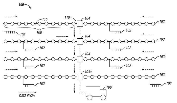
Fig. 1 represents a cable seismic data acquisition system;
Fig. 2 schematically illustrates a wireless seismic data acquisition system;
Fig. 3A shows a schematic representation of the system of Fig. 2 in more
detail;
Fig. 3B shows one embodiment of a wireless station unit having an
integrated seismic sensor;
Fig. 4 is a flow chart illustrating one methodology for deploying a seismic
data acquisition system according to the present disclosure; and
is Fig. 5 is one exemplary system for performing the methodology shown in
Fig. 4.
4
CA 02655117 2008-12-10
WO 2007/146774 PCT/US2007/070712
Detailed Description of the Disclosure
[008] In aspects, the present disclosure relates to devices and methods for
s controlling activities relating to seismic data acquisition. The present
disclosure is
susceptible to embodiments of different forms. There are shown in the
drawings,
and herein will be described in detail, specific embodiments of the present
disclosure with the understanding that the present disclosure is to be
considered
an exemplification of the principles of the disclosure, and is not intended to
limit
the disclosure to that illustrated and described herein.
[009] The methods and devices of the present disclosure may be utilized with
any type of seismic data acquisition system wherein seismic devices are
positioned over a terrain of interest according to a desired survey plan. For
context, the equipment and components of two such systems are discussed
is below.
[oolo] Fig. 1 depicts a typical cable-based seismic data acquisition system
100.
The typical system 100 includes an array (string) of spaced-apart seismic
sensor units 102. Each string of sensors is typically coupled via cabling to a
data
acquisition device (field box) 103, and several data acquisition devices and
associated string of sensors are coupled via cabling 110 to form a line 108,
which is then coupled via cabling 110 to a line tap or (crossline unit) 104.
Several crossline units and associated lines are usually coupled together and
then to a central controller 106 housing a main recorder (not shown). One
sensor unit 102 that is in use today is a velocity geophone used to measure
acoustic wave velocity traveling in the earth. Other sensor unit 102 that may
be
used are acceleration sensors (accelerometers) for measuring acceleration
associated with the acoustic wave. Each sensor unit may comprise a single
sensor element or more than one sensor element for multi-component seismic
sensor units.
5
CA 02655117 2008-12-10
WO 2007/146774 PCT/US2007/070712
[0011] The sensors 102 are usually spaced at least on the order of tens of
meters, e.g., 13.8 - 220.0 feet. Each of the crossline units 104 may perform
some signal processing and then store the processed signals as seismic
information for later retrieval. The crossline units 104 are each coupled,
either in
s parallel or in series with one of the units 104a serving as an interface
with
between the central controller 106 and all crossline units 104.
[0012] Referring to Fig. 2 there is schematically shown a wireless seismic
data
acquisition system. The system 200 includes a central controller 202 in direct
communication with each of a number of wireless sensor stations 208 forming an
array (spread) 210 for seismic data acquisition. Each sensor station 208
includes one or more sensors 212 for sensing seismic energy. Direct
communication as used herein refers to individualized data flow as depicted in
Fig. 2 by dashed arrows. The data flow may be bi-directional to allow one or
more of: transmitting command and control instructions from the central
is controller 202 to each wireless sensor station 208; exchanging quality
control
data between the central controller 202 and each wireless sensor station 208;
and transmitting status signals, operating conditions and/or selected pre-
processed seismic information from each wireless sensor station 208 to the
central controller 202. The communication may be in the form of radio signals
transmitted and received at the central controller 202 via a suitable antenna
204.
The term "seismic devices" includes any device that is used in a seismic
spread,
including, but not limited to, sensors, sensor stations, receivers,
transmitters,
power supplies, control units, etc.
[0013] The system 200 may operate in a passive mode by sensing natural or
random seismic energy traveling in the earth. The system 200 may operate in
an active mode using a seismic energy source 206, e.g., pyrotechnic source,
vibrator truck, compressed gas, etc., to provide seismic energy of a known
magnitude and source location. In many applications, multiple seismic energy
sources may be utilized to impart seismic energy into a subterranean
formation.
A representative seismic energy source is designated with numeral 206i.
Typically, activation (or more commonly, "shooting" or "firing") of the source
206i
6
CA 02655117 2008-12-10
WO 2007/146774 PCT/US2007/070712
is initiated locally by a mobile unit 502i. In one embodiment, the mobile unit
502i
includes a human operator who may utilize a navigation tool 504i to navigate
to a
source 206i and a source controller 506i to fire the source 206i. To navigate
the
terrain and to determine precise location coordinates, the navigation tool
504i
may be equipped with a global positioning satellite device (GPS device) and /
or
a database having predetermined coordinates (e.g., z coordinates).
[0014] The controller 202, the central station computer (CSC) 500 and a
central
server 520 exert control over the constituent components of the system 200 and
direct both human and machine activity during the operation of the system 200.
As discussed in greater detail below, the CSC 500 automates the shooting of
the
sources 206i and transmits data that enables the sensor stations 208 to self-
select an appropriate power usage state during such activity. The server 520
can be programmed to manage data and activities over the span of the seismic
campaign, which can include daily shooting sequences, updating the shots
acquired, tracking shooting assets, storing seismic data, pre-processing
seismic
data and broadcasting corrections. Of course, a single controller can be
programmed to handle most if not all of the above described functions. For
example, the CSC 500 can be positioned in or integral with the controller 202.
Moreover, in some applications it may be advantageous to position the
controller
202 and CSC 500 in the field, albeit in different locations, and the server
520 at a
remote location.
[0015] Fig. 3A is a schematic representation of the system 200 in more detail.
The central controller 202 includes a computer 300 having a processor 302 and
a memory 303. An operator can interface with the system 200 using a keyboard
306 and mouse or other input 308 and an output device such as a monitor 310.
Communication between remotely-located system components in the spread
210 and the central controller 202 is accomplished using a central transmitter-
receiver (transceiver) unit 312 operably connected to the central controller
202
along with an antenna 314.
7
CA 02655117 2008-12-10
WO 2007/146774 PCT/US2007/070712
[0016] The central controller 202 communicates with each wireless sensor
station 208. Each wireless sensor station 208 shown includes a wireless
station
unit 316, an antenna 318 compatible with the antenna 314 used with the central
controller 202, and a sensor unit 320 responsive to acoustic energy traveling
in
s the earth co-located with a corresponding wireless sensor station. Co-
located,
as used herein, means disposed at a common location with one component
being within a few feet of the other. Therefore, each sensor unit 320 can be
coupled to a corresponding wireless station unit by a relatively short cable
322,
e.g., about 1 meter in length, or coupled by integrating a sensor unit 320
with the
wireless station unit 316 in a common housing 324 as shown in Fig. 3B.
[0017] Location parameters (e.g., latitude, longitude, elevation, azimuth,
inclination, etc.) associated with a particular wireless sensor station help
to
correlate data acquired during a survey. These parameters determined prior to
a
survey using an expected sensor location and nominal sensor orientation and
is the parameters can be adjusted according to the present disclosure. The
location parameters are stored in a memory either in the central controller
202, in
the sensor station 208 or elsewhere. In one embodiment, the wireless sensor
station 208 includes a global positioning system (GPS) receiver (not shown)
and
associated antenna (not shown). The GPS receiver in such an embodiment can
be coupled to an appropriately programmed processor and to a clock to provide
location parameters such as position and location data for correlating seismic
information and for synchronizing data acquisition. Alternatively, location
parameters can be transmitted to and stored in the central controller and
synchronization may be accomplished by sending signals over the VHF/UHF
radio link independent of the GPS. Therefore, the on-board GPS can be
considered an optional feature of the disclosure. Location parameters
associated with sensor orientation can be determined by accelerometers and/or
magnetic sensors and/or manually.
[0018] Referring now to Fig. 4, there is shown an exemplary methodology 400
for deploying the above-described seismic data acquisition system. As will be
appreciated, the method 400 deploys a suite of field equipment in a manner
that
8
CA 02655117 2008-12-10
WO 2007/146774 PCT/US2007/070712
reduces the time and resources required to obtain a seismic survey. The use of
the above-described renewable seismic devices, some of which are positionally
aware, as opposed to physical visual markers, eliminates the need for field
survey, staking/flagging, and field clean-up steps. Thus, during a given
seismic
s data acquisition campaign, the seismic devices are in effect "touched" only
once
for placement, and touched only "once" for retrieval.
[0019] Initially, at step 402, a preliminary map is prepared that indicates
locations for each sensor station or other device. A term map, as used herein,
refers to a collection of data representative of the indicated locations of
the
seismic devices. Of course, the map can include other data as well. The data
can be in graphical or tabular format, a model utilizing mathematical
relationships, or any other suitable structure. In one embodiment, the
preliminary
map provides suggested locations for the seismic devices. The crew or mobile
units utilize a suggested location as a guide to make an in-field decision on
the
is final location for the seismic device. Thus, the crew has flexibility to
autonomously pick a favorable location for each seismic device. That is, the
crew can be provided with a set of guidelines, constraints, restrictions and
other
decision-influencing criteria that forms a microenvironment within which the
seismic device can be placed. The suggested location for each seismic device
is represented as a separate virtual or electronic flag or layout marker. That
is,
this flag resides digitally in a computer rather than physically on the
terrain. The
suggested location can be a point such as an X,Y coordinate or an area such as
an area within a circle having a specified radius from an X,Y coordinate. The
electronic layout markers can be compiled to form the preliminary map that
resides in a computer accessible database. As will become apparent, these
electronic flags or layout markers replace the wooden stakes, flags, paint or
other physical objects that conventionally is used to identify seismic device
locations. In some embodiments, the preliminary plan is a pre-plan as that
term
is understood in the art.
[0020] At step 404, a survey crew scouts a geographical area at which the
seismic survey will be conducted. Initially, the survey crew inspects the
9
CA 02655117 2008-12-10
WO 2007/146774 PCT/US2007/070712
suggested locations, along with the surrounding area, to note hazardous
conditions, whether natural or human-made. Generally speaking, these include
areas where exclusion rules apply due to Health, Safety, and Environment (HSE)
issues. The suggested locations are revised as needed to maintain a safe
s distance from any found hazardous condition. Thereafter, the survey crew
performs a cultural clearance for the suggested locations. This clearance can
include inspections for any situations or conditions that could impact or
violate
legal boundaries, regulatory rules, permits, contractual agreements and other
such restrictions. Again, the suggested locations are revised if needed to
ensure
compliance with any applicable rules, guidelines or agreements. Because these
inspections do not involve planting flags or other like activities that
disturb the
landscape, it should be appreciated that even after these preliminary scouting
activities, the terrain has been "untouched."
[0021] At step 406, mobile units 206i utilize the electronic layout flags or
is markers to navigate to the suggested locations for the seismic devices. It
should
be appreciated that because the layout markers are electronic, these layout
markers cannot be washed away, stolen or otherwise moved from their original
position. Thus, there is a higher likelihood that the mobile units 206i will
plant
the seismic devices proximate to the suggested locations. It should be
appreciated that in contrast to conventional surveying operations, the method
400 eliminates the need for a survey crew to add physical survey devices such
as sticks or paint to the terrain before planting the seismic devices.
[0022] At step 408, location parameters (e.g., latitude, longitude, azimuth,
inclination, etc.) are determined for the actual location at which each
seismic
device has been placed. In one embodiment, these parameters are determined
by the mobile units 504i using a GPS receiver. Other parameters might be
determined with a manual compass used by the crew or by one or more
magnetometers in the sensor unit. Parameters might also be determined using
multi-component accelerometers for determining orientation of the planted
CA 02655117 2008-12-10
WO 2007/146774 PCT/US2007/070712
sensor unit. In another embodiment, a GPS receiver, accelerometers,
magnetometers, and/or other sensors disposed in sensor unit, e.g., the station
or
sensor unit or both, determine the location parameters.
[0023] At step 410, the in-field determined location parameters are
transferred
s to the sensor stations, to a memory module carried by a mobile unit, and /
or a
memory module positioned at a central or remote location. These in-field
determined location parameters can be transmitted immediately or recorded in a
suitable memory module for later retrieval and transmission. Suitable transfer
arrangements include wireless transmission media and wire media such as data
cables. In certain embodiments, the location parameters are entered
automatically upon system activation and sensor station.
[0024] It will be appreciated that method 400 reduces the steps necessary to
conduct field operations for a seismic survey. After completing the scouting
and
hazard steps, this method omits visual markers, e.g., flags, stakes, paint,
and
is thereby eliminates the need for personnel to performing field surveys and
flagging for each location. Often, a conventional field survey and flagging
processes require repeating, as visual markers are easily moved or destroyed
by
external elements. Utilizing the preliminary map, together with data obtained
from LiDAR, full-feature/terrain feature imaging, aerial photos, slope and
vegetation analysis, DEM creation, allows concurrent field surveying and
layout
of seismic devices.
[0025] These in-field determined location parameters can used to form a final
map for the various seismic devices making up the seismic spread. This final
map, which contains precise in-field determined coordinates for the seismic
devices, can be used to control subsequent seismic data acquisition activities
and /or used in connection with a geographical information system that creates
stores, analyzes, and manages spatial data and associated attributes. In some
embodiments, the final plan is a post-plot as that term is understood in the
art.
For example, at step 412, the seismic grid can be used to control the shooting
sequence and power usage for the seismic spread. In another example, at step
11
CA 02655117 2008-12-10
WO 2007/146774 PCT/US2007/070712
414, the in-field determined location parameters can be included in a
navigation
database used in connection with "heads-up" navigation. In still another
example, at step 416, the in-field determined location parameters can be
integrated or correlated with acquired seismic data. Furthermore, at step 418,
s the in-field location parameter can be used even after completion of the
seismic
acquisition campaign. For example, the in-field parameter can be used in
connection with any subsequent seismic data acquisition activities, during
drilling
of wellbores, for characterizing the subterranean formation, and other like
applications.
[0026] Thus, from the above, one skilled in the art will appreciate that
embodiments of the present disclosure utilize an equipment layout process
requiring only one visit to place seismic devices and an equipment pickup
process requires only one visit to retrieve the seismic devices. Survey marker
placement visits and survey marker cleanup visits are not needed. Exemplary
is advantages arising from the teachings of the present disclosure include
cost
reductions and reduced health, safety, and environment risks. The risk
reduction
is based in part on reduced number of crew required, reduced number of tasks
crew must perform, and reduced total time spent in field. Other advantages
include reduced cost due to elimination of permit renewal/reapplication fees
resulting from schedule overruns.
[0027] Referring now to Fig. 5, there is shown an illustrative system 500 for
executing the method shown in Fig. 4. The system 500 includes a computer 502
utilized to prepare the preliminary survey plan, one or more navigation tools
504
that may be used to determine location parameters for seismic devices 506 in
the field, and a mobile server 508 that may be utilized to update the
preliminary
survey plan and develop one or more datasets, databases, knowledge bases,
and other information sets for managing the seismic survey campaign. The
server 508 may, of course, be the same as the computer 502.
[0028] The computer 502 may be programmed with known software such as a
MESA design package and other known seismic survey plan development
12
CA 02655117 2008-12-10
WO 2007/146774 PCT/US2007/070712
software and be provided with data such as historical seismic data,
(Geographical Information Services) GIS data, and other such knowledge bases.
The computer 502 provides a preliminary plan that includes suggested location
parameters for seismic equipment 506, such as seismic stations and sources.
s Field crew convey the seismic equipment 506 and the navigation tool 504 into
the area to be surveyed. At the suggested locations, the field crew positions
the
seismic equipment 506 at or near the suggested location parameter for each
piece of seismic equipment 506 and use a location sensor that may be in the
navigation tool 504, such as a GPS device or other sensor for deterring a
location parameter, to determine precise location parameters for each piece of
seismic equipment 506. Thus, location data is obtained at about the same time
that the seismic equipment 506 is positioned in the field. The navigation tool
504
may record the location parameters and thereafter furnish the recorded
location
parameters to the mobile server 508. The mobile server 508 may utilize the
is received data from the navigation tool 504 for the several purposes shown
in
blocks 412, 414, 416, and 418 shown in Fig. 4 or for other uses.
[0029] Furthermore, while the present disclosure has been discussed in the
context of seismic data acquisition, it should be understood that the
teachings of
the present disclosure can be advantageously applied to any situation that
involve complex flow of data and interaction between multiple personnel that
are
tasked with collecting, recording, processing and transmitting information.
[0030] The foregoing description is directed to particular embodiments of the
present disclosure for the purpose of illustration and explanation. It will be
apparent, however, to one skilled in the art that many modifications and
changes
to the embodiment set forth above are possible without departing from the
scope
of the disclosure. It is intended that the following claims be interpreted to
embrace all such modifications and changes.
13