Note: Descriptions are shown in the official language in which they were submitted.
CA 02655137 2008-12-11
WO 2008/005158 PCT/US2007/013800
METHOD AND APPARATUS FOR DIRECT ENERGY CONVERSION
CROSS-REFERENCE TO RELATED APPLICATIONS
The present patent application is based on, and claims priority from, U.S.
provisional Application No. 60/813,341, filed June 14, 2006, which is
incorporated herein
by reference in its entirety.
BACKGROUND OF THE INVENTION
1. Field of the Invention
The present invention relates to a method and apparatus for direct energy
conversion. More specifically, the invention relates to a method and apparatus
for direct
energy conversion for extracting electrons by employing the unique properties
of Type II
high temperature superconductors.
2. Related Art
The following definitions are used herein:
Atomic Elastic Force: In the normal state of matter, electrons are kept apart
by
mutual repulsion based on their electrostatic and magnetic properties. In the
case of Type
II superconductors, for example, YBCO, electrons that normally repel one
another
experience an overwhelming attraction to link up and form Cooper pairs when
the
material drops below its critical temperature, Tc. When these electrons form
Cooper pairs,
they take on the character of bosons, meaning that all the electrons have the
same spin
and energy level. Only bosons can condense and occupy a ground state that has
a lower
total energy than that of the normal ground state. This behavior suggests that
Cooper pairs
are coupling over hundreds of nanometers, three orders of magnitude larger
than the
crystal lattice spacing. The effective net attraction between the normally
repulsive
electrons produces binding energy on the order of milli-electron volts, enough
to keep
them paired at low temperatures. Electrons in the Cooper pair state can be
considered
- 1 -
CA 02655137 2008-12-11
WO 2008/005158 PCT/US2007/013800
compressed because they are closer to each other than in the normal (non-
superconducting) state. In many ways, Cooper pair electrons are much like a
mechanical
spring under compression. The atomic elastic force is defmed as the
compressive force
provided by millions of Cooper pairs in this ground state. The available
potential energy
increases when electrons close their interaction distance. This potential
energy is released
when the Cooper pair electrons absorb the energy of photons and are forced to
revert
from their lower total energy ground state to the higher total energy normal
ground state.
When this happens, the potential energy is released in a fraction of a second,
producing
spontaneous symmetry breaking (also known as Photon Cooper Pair Breaking). The
cycle
is repeated once the electron ejects a photon of a lower energy level and
transitions back
to the lower total energy ground state.
B: The magnetic field in which a superconductor is placed
Cooper pair: Two electrons that appear to "team up" in accordance with
conventional theories of superconductivity, despite the fact that they both
have a negative
charge and normally repel each other. Below the superconducting transitian
temperature
T,., paired electrons form a condensate (a macroscopically occupied single
quantum state),
which flows without resistance. In addition, conventional theory holds that
Cooper pairs
form on the superconductor surface and spin as one large Cooper pair. In
effect, Cooper
pairs' electrons are so tight that they reflect the static flux away from the
surface of the
superconductor. This reflection of the static flux induces a thin sheet of
current that leaves
few fixed holes in the lattice structure, so that the current sheet acts like
a moving mirror
reflecting back the magnetic flux with the same polarity and force with which
it was
received.
Flux: A magnet's lines of force.
Fluxoid (also known as flux line,fluxon, vortex): One of the microscopic
filaments
of magnetic flux that penetrates a Type II superconductor in the mixed state,
consisting of
a normal core in which the magnetic field is large, surrounded by a
superconducting
region in which flows a vortex of persistent supercurrent which maintains the
field in the
core.
Conventional Flux-Pinning: The phenomenon where a magnet's flux become
trapped or "pinned" inside a current-carrying Type II superconducting material
in spite of
the Lorentz force acting to expel it from inside the Type 11 superconducting
material. This
-2-
CA 02655137 2008-12-11
WO 2008/005158 PCT/US2007/013800
pinning binds the superconductor to the magnet at a fixed distance. Flux
pinning is only
possible when there are defects in the crystalline structure of the
superconductor (usually
resulting from grain boundaries or impurities).
H,: The "critical field" or maximum magnetic field that a superconductor can
endure before it is "quenched" and returns to a non-superconducting state.
Usually a
higher T. also brings a higher H,
Meissner Effect: The exhibiting of diamagnetic properties to the total
exclusion of
all magnetic fields. The Meissner Effect is a classic hallmark of
superconductivity.
Quanium efficiency: In an optical source or detector, the ratio of the number
of
output quanta to the number of input quanta.
Quench: The phenomenon where superconductivity in a material is suppressed;
usually by exceeding the maximum current the material can conduct (Jc) or the
maximum
magnetic field it can withstand (Hc).
T,: The critical transition temperature below, which a material begins to
superconduct.
Thin Film (Deposition): A process for fabricating ceramic superconductors to
more precisely control the growth of the crystalline structure to eliminate
grain
boundaries and achieve a desired Tc. Two types of thin film deposition are
Pulsed-Laser
Deposition (PLD) and Pulsed-Electron Deposition (PED) of the material.
Vortices (plural of vortex): Swirling tubes of electrical current induced_ by
an
external magnetic field into the surface of a superconducting material that
represent a
topological singularity in the wave function. These are particularly evident
in Type II
superconductors during "mixed-state" behavior when the surface- is just
partially
superconducting. Superconductivity is completely suppressed within these
volcano-
shaped structures. The movement of vortices can produce a pseudo-resistance
and, as
such, is undesirable. While superconductivity is a "macroscopic" phenomenon,
vortices
are a "mesoscopic" phenomenon.
YBCO: An acronym for a well-known ceramic superconductor composed of
Yttrium, Barium, Copper and Oxygen. YBCO was the first truly "high
temperature"
ceramic superconductor discovered, having a transition temperature well above
the
boiling point of liquid nitrogen (a commonly available coolant). Its actual
molecular.
-3-
CA 02655137 2008-12-11
WO 2008/005158 PCT/US2007/013800
formula is YBa2Cu3O7, making it a "1-2-3" superconductor. YBCO compounds
exhibit d-
wave electron pairing.
Superconductivity, discovered in- 1911 by Heike Kamerlingh Onnes, is a
phenomenon occurring in many electrical conductors at extremely low
temperatures (on
the order of -200 Celsius). In this phenomenon, the electrons -responsible
for conduction
undergo a collective transition into an ordered state, an electronic fluid
consisting of
Cooper pairs. Attractive force between electrons from the exchange of phonons
causes
the pairing of electrons in Cooper pairs. As a result of its ordered state,
the Cooper pair
fluid has many unique and remarkable properties, including the vanishing of
resistance to
the flow of electric current, the appearance of a large diamagnetism and other
unusual
magnetic effects, substantial alteration of many thermal properties, and the
occurrence of
quantum effects otherwise observable only at the atomic and subatomic level.
In normal conductors, changing fields are required to induce other fields. In
superconductors, static fields can also induce other fields. At the root of
these effects lies
a dramatic change in the permittivity and permeability of a superconductor
(electron
condensation).
One of the unusual magnetic effects exhibited by superconductors is the
Meissner
(or Meissner-Ochsenfeld) Effect. Meissner and Ochsenfeld discovered that a
metal cooled
into the superconducting state in a moderate magnetic field expels the field
from its
interior. Supercoinductors are defined as having "a state of perfect
diamagnetism." Perfect
diamagnetism implies that the superconductor material does not permit an
externally
applied magnetic field to penetrate into its interior. Effectively,
superconductors block
magnetic fields by modifying the magnetic length path, which is known as
reluctance.
The exclusion of magnetic flux by a superconductor costs some magnetic energy.
As long as this cost is less than the condensation energy gained by going from
the normal
to the superconducting phase, the superconductor will remain completely
superconducting in an applied magnetic field. If the applied field becomes too
large, the
cost in magnetic energy will outweigh the gain in condensation energy, and the
superconductor will become partially or totally normal. The manner in which
this occurs
depends on the geometry and the material of the superconductor. The geometry
that
produces' the simplest behavior is that of a very long cylinder with the
magnetic field
-4-
CA 02655137 2008-12-11
WO 2008/005158 PCT/US2007/013800
applied parallel to its axis. Two distinct types of behavior may then occur,
depending on
the type of superconductor - Type I or Type II.
Below a critical magnetic field H,,, which increases as the temperature
decreases
below T., the magnetic flux is excluded from a type I superconductor, which is
said to be
perfectly diamagnetic. For a Type II superconductor, there are two critical
magnetic
fields, the lower critical magnetic field H,,, and the upper critical.
magnetic field HCZ. In
applied magnetic fields less than H,,i, the superconductor completely excludes
the
magnetic field, just as a type I superconductor does below H,'. At magnetic
fields just
above Ho, however, flux begins to penetrate the superconductor, not in a
uniform way,
but as individual, isolated microscopic filaments called fluxoids or vortices,
each carrying
one quantum of magnetic flux, h/2e. In other words, high levels of static flux
are also
known to cause vortices in Type II superconductors. The flux penetration is
hindered by
microscopic inhomogeneities that pin (trap) vortices. As a result, a critical
state is formed
with some gradient of flux density determined by the critical current.
Vortices provide a means to modulate static flux because they produce a
magnetic
channel whereby the static flux moves unhindered, without losses from one
point to a
second point. When a Type II superconductor is placed in a magnetic field B,
where Hc1 <
,y and HCZ are the lower and upper critical fields, respectively, the
B < H,,Z, and where Hr
magnetic vortices that penetrate the material should form a uniform triangular
lattice
(Abrikosov vortex lattice), with a lattice spacing determined by the strength
of B. If B is
increased, the vortices become more closely spaced and their cores start to
overlap.
Currently theory holds that the static flux "B" causes the vortices in the
surface of the
Type II superconductor thin film to spin up. If the Type TI superconductor
thin film is
configured as a cylinder, the spinning of the vortices in its surface will
only cause a
surface current equal and opposite to the static flux, which is enough to
cause the
magnetic flux to pin to the longitudinal axis of the cylinder. At Hc2 the
vortex lattice and
the Cooper pairing of the electrons disappear and the material becomes normal.
Anisotropy effects are fundamental to superconductivity. Just about all-
crystalline
superconductors are in principle expected to show some anisotropy effects.
There are
several classes of materials with anisotropic superconducting properties,
including the
class of bulk anisotropic superconductors (for example, some of the transition
metals) and
the class of superconducting thin films. When the thickness of a film is less
than the
-5-
CA 02655137 2008-12-11
WO 2008/005158 PCT/US2007/013800
coherence length, the Cooper pairs can only interact with their neighbors in
the plane of
the film. In this case, the 'film is commonly referred to as a two-dimensional
superconductor, because the Cooper pairs only interact in two directions.
Lowering the effective dimensionality of a superconductor from three to two
dimensions has important and measurable consequences, deriving from the fact
that the
length scale for superconductivity in the direction perpendicular to the film
is now the
film thickness rather than the coherence length. Usually, layered
superconductors show
3D anistropic superconductivity like the bulk transition metals, but sometimes
they show
2D superconductivity like thin films, and sometimes they even show entirely
new effects.
Research indicates that when a photon of a given energy level and wavelength
is
shot into the Type II superconductor, the photon is absorbed by the Cooper
pair. This
infusion of photon energy causes these electrons to break apart, and to seek a
new higher
quantum orbit. This starts a chain reaction or avalanche - not unlike a
nuclear reaction -
only without the adverse side effects. Previously published research findings
show a
quantum efficiency of up to 340 from each photon.
It is a well-known fact that permanent magnets produce a static flux that
emanates
off their end poles. Many devices have been invented that use this static flux
to produce
electrical power we use today. Static flux is ideal for converting mechanical
energy into
electrical energy. The basic process has not changed in 100 years. The most
common
method uses a moving armature that rotates inside windings, making and
breaking the
magnetic circuit. As Faraday and Maxwell discovered, only then can the static
flux be
used to extract energy. Faraday's law of induction (Equation 1) states that
there is a
counter electromagnetic force generated in a coil of wire when there is a
difference in
flux over time:
s = -N d1DB (Eq= 1)
dt
where the magnetic flux (D, = B A cosB, and where B is the magnetic field, A
is the
surface area of the coil, and 0 is the angle between B and a line drawn
perpendicular to
the face of the coil.
-6-
CA 02655137 2008-12-11
WO 2008/005158 PCT/US2007/013800
The minus sign signifies that the direction of the induced EMF will be such
that
the magnetic field produced by the induced EMF resists the change in magnetic
flux. The
presence of the minus sign is referred to as Lenz's Law.
If a device can produce a difference in the flux density passing through a
typical
coil, then Faraday's law states there would be a counter electromagnet force
developed
across the windings. All of the present day devices that use mechanical energy
perform
this one simple task. Regardless of the complexity, the device only makes and
breaks the
flux lines, thereby creating a difference in flux, causing the secondary
effect known as
counter EMF. Man over the years has tried many different methods to produce
electrical
=10 energy. Over time the demands for electrical energy is ever expanding. Man
still uses
massive generating plants linked together with thousands of miles of power
distribution
high voltage lines, which have to be maintained and require large financial
investments.
It is to the solution of these and other problems that the present invention
is
directed.
SUMMARY OF THE INVENTION
It is accordingly a primary object of the present invention to provide a
method and
apparatus for extracting massive amounts of electrons developed and coupled by
modulating the static magnetic flux emanating from the poles of permanent
magnets.
It is another object of the present invention to provide a device that will
provide
electrical energy to power any electrical load without- producing any
additional COZ
emissions.
It is still another object of the present invention to use Type II
superconductors to
improve the manufacture of electrical power.
It is still another object of the present invention to provide a method and
apparatus
for converting the potential energy from permanent magnets to kinetic energy
by
modulating the flux of permanent magnets.
These and other objects are achieved by a direct energy conversion generator
that
combines the known properties of Type II superconductors, including the
Meissner
Effect, to create vortices to control and modulate static flux coupled in a
conventional
magnetic circuit, where the laws of induction are used to produce an
electrical potential to
-7-
CA 02655137 2008-12-11
WO 2008/005158 PCT/US2007/013800
drive motors, lights, and other useful devices. This electrical energy is
manufactured at
the atomic level and does not require the use of moving armatures.
The direct energy conversion generator employs a vortex channel based on the
Meissner Effect known to expel and pin a fixed magnetic field of a specific
value
emanating from the poles of a permanent magnet. A laser, a permanent magnet
with an
axial channel coincident with the magnet's axis, fiber optics for carrying
photons from the
laser through the axial channel of the magnet to the vortex channel, a
diffusing
mechanism between the permanent magnet and the vortex channel for evenly
expanding
the photon beam to the diameter of the vortex channel, and a transformer
composed of
two separate windings. The diffusing mechanism can be a thin diffusing lens or
any other
mechanism that can diffuse the incoming photons from the point source provided
by the
fiber optics into a larger area capable of covering the frontal surface area
of the vortex
channel. The transformer windings are arranged in a circuit having a first
path through the
permanent magnet and a first coil of the transformer windings; and a second
path through
the permanent magnet, the vortex channel, and the second coil of the transfer
windings.
The vortex channel comprises a plurality of vortex tubes of circular cross-
section
arranged in a bundle with their longitudinal axes parallel to each other. The
cross-section
of the bundle can be any configuration, for example, approximately circular,
approximately square, and approximately rectangular, etc. The number of vortex
tubes in
the bundle is on the order of hundreds or thousands.
The vortex tubes are glass tubes having an exterior surface (which includes
the
tube ends), a first buffer layer covering the exterior surface, a second
buffer layer
covering the first buffer layer, a Type II superconductor thin film covering
the second
buffer layer, and an insulating layer covering the superconductor thin film.
The vortex
tubes are switchable between a superconducting state and a non-superconducting
state;
and work together as a vortex channel to guide static magnetic flux in one
direction from
one end of the vortex tubes to the other, with very low or no loss, or at
least very low
losses.
The photons emitted by the laser must have a wavelength that will be easily
absorbed by the Cooper pairs in the Type II superconductor thin film and
provide the
correct packet of energy, so that the liberated electron will jump precisely
to the new
quantum orbit. Type II YBCO material is known to have a very sharp resonance
at 930
-~-
CA 02655137 2008-12-11
WO 2008/005158 PCT/US2007/013800
nm, at which it will absorb photons at extremely high efficiencies, causing it
to revert
back to the non-superconducting state.
When the vortex channel is in the non-super conducting state, it acts as a
ceramic
or insulator having the permeability of air, static flux is free to flow
through the first path.
When the vortex channel is in the superconducting state, it guides static flux
quanta
through the vortex channel. The static magnetic flux is held in a compressed
closed loop,
and static flux flows through the second path.
Photon Cooper breaking is used to toggle the Type II superconductor thin film
(and thus the vortex channel) between the superconducting state and the non-
superconducting state, thereby providing a time-varying magnetic field
enabling power to
be extracted using traditional means. In effect, the vortex channel acts like
an ideal
inductor with infinite permeability when it is fully superconducting, shorting
the static
flux to its far side (the second coil), allowing the static flux to move
through what would
otherwise be equivalent to a massive air gap without loss due to flux leakage.
When
Cooper pair breaking takes place, the vortex channel is forced to switch back
into a (non-
superconducting) ceramic, effectively adding a massive air gap into the
magnetic loop
and changing the reluctance of the magnetic circuit. Toggling the vortex
channel allows
the direct energy conversion generator to command passive conventional
electrical
components like an inductor to become inert and take on the physical
properties of air.
Other objects, features and advantages of the present invention will be
apparent to
those skilled in the art upon a reading of this specification including the
accompanying
drawings.
BRIEF DESCRIPTION OF THE DRAWINGS
The invention is better understood by reading the following Detailed
Description
of 'the Preferred Embodiments with reference to the accompanying drawing
figures, in
which like reference numerals refer to like elements throughout, and in which:
FIGURE 1 A is a schematic illustration of a direct energy conversion generator
in
accordance with the present invention.
-9-
CA 02655137 2008-12-11
WO 2008/005158 PCT/US2007/013800
FIGURE 1B is a schematic illustration of the magnetic flux path or loop of the
direct energy conversion generator of FIGURE 1A when the vortex channel is in
the non-
superconducting state.
~
FIGURE 1 C is a schematic illustration of the magnetic flux path or loop of
the
direct energy conversion generator of FIGURE iA when the vortex channel is in
the
superconducting state.
FIGURE 2 is a cross-sectional view of the vortex channel of the. direct energy
conversion generator.
FIGURE 2A is an enlarged, cross-sectional view of one of the vortex tubes of
the
vortex channel.
FIGURE 3 is a schematic illustration showing the manner in which static flux
is
compressed and twisted as it enters the center of each vortex tube and is
conducted into a
very high virtual permeability thread.
FIGURE 4 is a graph illustrating how the vortex channel acts as a photon-
activated switch used to modulate the static magnetic field of the permanent
magnet of
the direct energy conversion generator.
FIGURE 5 is the cross-sectional view of the vortex channel as shown in FIGURE
2, illustrating the area of influence surrounding the channel of the direct
energy
conversion generator.
FIGURE 5A is. the cross-sectional view of the vortex tube of FIGURE 2A,
illustrating the area of influence surrounding the vortex tube.
FIGURE 6 is a schematic illustration of the direct energy conversion generator
in
use as a source of electrical energy.
FIGURE 7 is a flow diagram showing the energy conversion process carried out
by the direct energy conversion generator in accordance with the present
invention. -
FIGURE 8 is an energy generation curve for the- direct energy conversion
generator based on a hypothetical prototype design thereof.
DETAILED DESCRIPTION OF THE PREFERRED EMBODIMENTS
In describing preferred embodiments of the present invention illustrated in
the
drawings, specific terminology is employed for the sake of clarity. However,
the
-10-
CA 02655137 2008-12-11
WO 2008/005158 PCT/US2007/013800
invention is not intended to be limited to the specific terminology so
selected, and it is to
be understood that each specific element includes all technical equivalents
that operate in
a similar manner to accomplish a similar purpose.
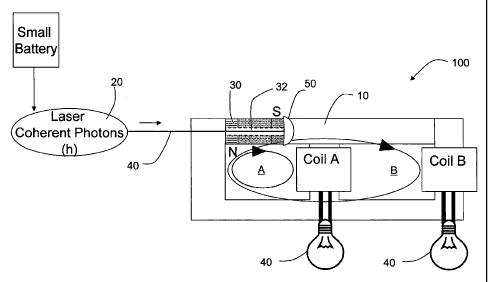
The present irivention is a direct energy conversion generator 100 (shown in
FIGURES lA-1C) that combines the known properties of Type II superconductors,
including the Meissner Effect, to assist in the control of vortices to
modulate static flux
(indicated by the arrows Fs in FIGURES lB and 1C). In the direct energy
conversion
generator, flux is coupled in a conventional magnetic circuit as described in
greater detail
hereinafter, where the laws of induction are used to produce an electrical
potential to
drive motors, lights, and other useful devices. This electrical energy is
manufactured at
the atomic level and does not require the use of moving armatures.
Referring now to FIGURES 2 and 2A, the direct energy conversion generator 100
employs a vortex channel 10 based on the Meissner Effect known to expel and
pin a fixed
magnetic field of a specific value emanating from the poles of a permanent
magnet or an
electromagnet. The vortex channel 10 comprises a plurality of vortex tubes 12
of circular
cross-section arranged in a bundle with their longitudinal axes parallel to
each other. As
illustrated in FIGURE 2, the bundle has an approximately circular cross-
section (a circle
C is superimposed on the cross-section of the vortex channel 10 for the
purpose of
illustrating its approximately circular shape). However, the cross-section
need not be
approximately circular, but can be any configuration, for example,
approximately square,
approximately rectangular, etc. The number of vortex tubes 12 in the bundle is
on the
order of hundreds or thousands.
As shown in FIGURE 2A, the vortex tubes 12 are glass tubes 12a having an
exterior surface 12b (which includes the tube ends), a first buffer layer 12c
covering the
exterior surface 12b, a second buffer layer 12d covering the first buffer
layer, a Type II
superconductor thin film 12e covering the second buffer layer, and an
insulating layer 12f
covering the superconductor thin film. As discussed in greater detail
hereinafter, the
vortex tubes 12 are switchable between a superconducting state and a non-
superconducting state; and work together as a vortex channel 10 to guide
static magnetic
flux in one direction from one end of the vortex tubes 12 to the other, with
very low or no
loss, or at least very low losses.
-11-
CA 02655137 2008-12-11
WO 2008/005158 PCT/US2007/013800
In an exemplary embodiment, the vortex channel 10 is constructed of
approximately 500 vortex tubes. Each glass tube 12a has a maximum 0.0125-inch
outside
diameter and a 1.0- inch length. The first buffer layer 12c is a thin film
coating of Y203
stabilized with Zr02. The second buffer layer 12d 'is a thin film coating of
cerium oxide
(CeOZ). The superconductor thin film 12e is a thin film of YBCO. The
insulating layer
12f is a very thin layer of Parylene.
Type II superconductor thin film (YBCO) is deposited over the second buffer
layer 12d (CeOZ). The Type II superconductor to make a vortex tube, the
exterior surface
12b of the glass tube 12a must first be cleaned of Si02, for example using an
Excimer
laser in a vacuum. The first buffer layer 12c (a thin film coating of Y203
stabilized with
Zr02) keeps the tube material (Si) from migrating into the Type II
superconductor thin
film .12e (YBCO) and making it ineffective as a superconductor.
To improve the crystal lattice interface between the Type II superconductor
thin
film 12e (YBCO) and the first buffer layer 12c (thin film coating of Y203
stabilized with
Zr02), a second buffer layer 12d is required. Cerium oxide (CeO2) is selected
for the
second buffer layer 12d because it provides an ideal base for the deposit of
the YBCO
thin film. The second buffer layer 12d brings the error between the crystal
lattice interface
to - 0.5%. Next, a very thin film 12e of the thin film 12e (YBCO) is deposited
in a very
thin shell over tlie first and second buffer layers 12c and 12d so as to cover
the exterior
surface 12b of the tube without defects.
After the Type II superconductor thin film 12e (YBCO) is deposited, it is
coated
with a very thin layer of Parylene, which is an electrical insulator that is
capable of
coating the Type II superconductor thin film 12e (YBCO) one molecule at a time
without
gaps, to electrically isolate the vortex tubes 12 from each other, making the
vortex
generated within each vortex tube 12 operate independently of the vortices
generated in
the other vortex tubes 12, neutralizing the Lorentz force, and locking each
vortex tube 12
to a fixed position within the vortex channel 10 so that each vortex tube 12
works
independent of its neighbor.
Referring again to FIGURES lA-1C, in addition to the vortex channel, the
direct
energy conversion generator 100 includes a laser 20, a permanent magnet or
electromagnet 30 (preferably cylindrical) with an axial channel 32 coincident
with the
magnet's axis, fiber optics 40 for carrying photons from the laser 20 through
the axial
- 12-
CA 02655137 2008-12-11
WO 2008/005158 PCT/US2007/013800
channel 32 of the magnet or electromagnet 30 to the. vortex channel, a
diffusing
mechanism 50 between the permanent magnet or electromagnet 30 and the vortex
channel
for evenly expanding the photon beam to the diameter of the vortex channel 10,
and a
transformer composed of two separate windings. The diffusing mechanism 50 can
be a
5 thin diffusing lens or any other mechanism that can diffuse the incoming
photons from
the point source provided by the fiber optics 40 into a larger area capable of
covering the
frontal surface area of the vortex channel 10. The permanent magnet or
electromagnet 30,
the vortex channel 10, and the transfer windings make up the rest of the
circuit.
The transformer windings are arranged in a circuit having a first path A(shown
in _
10 FIGURE iB) through the permanent magnet or electromagnet 30 and a first
coil A of the
transformer windings; and a second path B (shown in FIGURE. 1 C) through the
permanent magnet or electromagnet 30, the vortex channel 10, and the second
coil B of
the transfer windings. When the amount of magnetic flux flowing through the
transformer
windings changes due to modulation of the magnetic flux by the vortex channel,
electricity is produced. This electricity can be used to power a load 60, for
example, a
light bulb.
The photons emitted by the laser 20 must have a wavelength that will be easily
absorbed by the Cooper pairs in the Type II superconductor thin film and
provide the
correct packet of energy, so that the liberated electron will jump precisely
to the new
quantum orbit.
Thus, in the exemplary embodiment in which the Type II superconductor thin
film
12e is YBCO, the laser 20 has a wavelength of 930 nm with a power output of
approximately 1-watt, and electron-photon conversion quantum efficiency of at
least
30%. The transformer conventionally includes a ferromagnetic core (for
example, soft
ferrites) and windings - made of a conductive material like copper wire or a
superconductive wire. The flux density of the permanent magnet or
electromagnet 30 is
approximately 2000 gauss at the magnet poles.
It is noted that Type II YBCO materials normally saturate at a flux density of
approximately 2000 gauss. This saturation is prevented in the direct energy
conversion
generator 100 in accordance with the present invention by the design and
fabrication of
the vortex channel. For example, if the vortex channel 10 is made up of
approximately
500 vortex tubes, then each vortex tube 12 must carry a flux density of
approximately 4
-13-
CA 02655137 2008-12-11
WO 2008/005158 PCT/US2007/013800
gauss. A flux density of approximately 4 gauss is still well above the normal
amount that
Type II YBCO materials can carry without saturation. However, the rotating
Cooper pairs
in the Type II superconductor thin film 12e deposited on the outside surface
of each
vortex tube 12 exert an atomic force that emanates from the moving electrons
and
interacts with the incoming static flux, causing the static flux to be pinned
to the centers
of the vortex tubes by atomic force pinning. This flux pinning is used to
extract the
potential energy through the operations of the direct energy conversion
generator.
As shown in FIGURE 3, static flux is compressed and twisted as it enters the
center of each vortex tube 12 and is conducted into a very high virtual
permeability thread
where it is maintained at a distance from the outside surface of the vortex
tube 12e. The
electrons orbiting inside the crystal lattice structure on the surface of the
vortex tubes 12
provide the dynamic force to do this work function. The dynamic force is
supplied by the
superconductor thin film 12e only when it is in the superconducting state.
Reflection of
the static flux induces a thin sheet of current, so that the current sheet
acts like a moving
mirror reflecting back the magnetic flux with the same polarity and force with
which it
was received. The thin sheet of current covers the circumference of the vortex
tubes 12
along their full lengths, compressing the static flux over the full lengths of
the vortex
tubes 12 and thus over the full length of the vortex channel 10.
When the vortex channel 10 is in the non-super conducting state, it acts as a
ceramic or insulator having the permeability of air, static flux is free to
flow through path
A. When the vortex channel 10 is in the superconducting state, it guides
static flux quanta
through the vortex channel 10, which is a low energy magnetic circuit for the
purpose of
generating electrical energy. The static magnetic flux is held in a compressed
closed loop,
and static flux flows through path B.
Each vortex tube 12 can only handle a given amount of static flux before it
will
saturate. The vortex channel '10 therefore must be made up of enough vortex
tubes 12 to
spread out the static flux by passing it through their open centers away from
the Type II
superconductor thin film when the Type IT superconductor thin film 12e is in
its
superconducting state. The vortex channel, while in its superconducting state,
produces a
super high virtual permeability state, as a result, provides a new low energy
path for the
static flux to flow through. The higher the permeability, the less energy it
takes for the
-14-
CA 02655137 2008-12-11
WO 2008/005158 PCT/US2007/013800
static flux to flow. Static flux always takes the path of least resistance,
i.e., lowest energy
path.
FIGURE 4 is a graph illustrating how the vortex channel 10 acts as a photon
activated magnetic switch to modulate the magnetic field of the permanent
magnet or
electromagnet 30 of the direct energy conversion generator 100. When the Type
TI
superconductor thin film 12e is in its superconducting sta;te, the combination
of the
Meissner Effect and the atomic elastic forces between the electrons and the
static flux
results in flux pinning at the center of the vortex tubes. More specifically,
rotating Cooper
pairs around the exterior surface of the vortex channel 10 create a massive
pinning force
in the center of the vortex channel, whereby the static flux is held off the
interior and
exterior surfaces of the vortex tubes 12 due to the Meissner Effect and the
force excreted
by the electrons magnetic forces in opposition to the static magnetic forces,
and is pinned
inside the vortex tubes 12 along their longitudinal axes so as to have no
contact with the
superconductor thin film. As a result of this geometry, the direct energy
conversion
generator 100 can operate at much higher flux density than would otherwise be
possible,
because the static flux does not come into direct contact with the
superconducting thin
film.
In the normal (that is, the non-superconducting) state, the vortex channel 10
does
not affect the magnetic path, because the vortex channel 10 (and more
specifically, the
superconductor thin film 12e that coats the vortex tubes 12) is just a non-
superconducting
ceramic, with no known magnetic properties of any kind. Static flux emanating
off the
south pole of the permanent magnet or electromagnet 30 is coupled or linked to
the
magnetic path provided by the inductor in path A and returned to the north
pole by the
magnetic path provided by the inductor loop completing the magnetic loop.
In addition, the atomic forces found in the crystal lattice structure of the
Type II
superconductor thin film 12e play a role in pinning the static flux. These
forces are
applied evenly around the circumference of each vortex tube 12e along its
entire length,
analogous to the manner in which a magnetic field is evenly distributed around
the
circumference of a wire along its entire length when current is flowing
through that wire.
Each vortex tube 12 acts independently, pulling flux quanta into its center.
The area of
influence is much greater then the frontal area of each vortex tube, as shown
in FIGURES
5 and 5A. More energy is required for magnetic flux to take a path outside of
this area of
-15-
CA 02655137 2008-12-11
WO 2008/005158 PCT/US2007/013800
influence of the vortex tube 12 than to take a path within the area of
influence. Only the
longitudinal axis of the vortex tube 12e represents the lowest energy path or
the preferred
path.
By combining many man made vortex tubes 12 together an artificial or virtual
high permeability vortex channel 10 is defined. A disk of virtual high
permeability rotates
at the front or upstream end of each vortex tube. 12 This virtual high
permeability
increases radially in an inward direction from the circumference to the
longitudinal axis
of each vortex tube 12, providing an ever-increasing pinning force that
induces the flux
quanta to flow towards the longitudinal axis of each vortex tube 12 and away
from its
outer surface.
Both the Meissner Effect and the atomic elastic forces, i.e., magnetic and
static
forces of the electrons, found circulating in the super thin sheet of current
flowing on the
extemal surface of the vortex tubes 12, force the static flux away from the
Type II
superconductor thin film 12e, pinning the static flux to the longitudinal axis
of each
vortex tube.
This pinning is only possible because the Type II superconducting material
resists
the penetration of the static flux emanating off the surface of one of the
poles of the
permanent magnet. This static flux bias causes the Type II superconductor to
develop a
counter force, known as "J", or current flow, which flows on the external
surface of the
vortex tubes 12 in the form of a supper thin sheet of current and is
restricted to the outside
surface of the thin film 12e of each vortex tube 12.
The energy cost of developing this counterforce is zero, with the exception
that
the environment must be maintained at LN2 temperatures. In effect, the vortex
tubes 12
are performing a work funetion by producing a low energy flux channel, which
is
preferred by the static flux emanating off the pole of the permanent magnet or
electromagnet 30. For static flux to take a different path would require more
energy and
therefore is rejected. Static flux will always pass through the path of lowest
energy or
least resistance. The path of least resistance is always the longitudinal axis
AL of the
vortex tube. Because the vortex channel 10 is made up of many vortex tubes 12,
the static
flux will be forced to fall into one of these low energy paths rather than to
turn and select
path A. When the vortex channel 10 is in the superconducting state, path B
will provide a
-16-
CA 02655137 2008-12-11
WO 2008/005158 PCT/US2007/013800
million times lower energy path for the static flux to follow back to the
opposing pole, in
this case the opposite pole of the same magnet.
A process known as "photon Cooper breaking" is used to toggle the Type TI
superconductor thin film 12e between the superconducting state and the non-
superconducting state, thereby providing a time-varying magnetic field
enabling power to
be extracted using traditional means. In effect, the vortex channel 10 acts
like an ideal
inductor with infinite permeability when it is fully superconducting, shorting
the static
flux to its far side (coil B), allowing the static flux to move through what
would otherwise
be equivalent to a massive air gap without loss due to flux leakage. When
Cooper pair
breaking takes place, the vortex channel 10 is forced to switch back into a
(non-
superconducting) ceramic, effectively adding a massive air gap into the
magnetic loop
and changing the reluctance of the magnetic circuit. It is noted that when the
YBCO thin
film is in the superconducting state it is a perfect diamagnetic material,
rather than a
ceramic. Toggling the vortex channel 10 allows the direct energy conversion
generator
100 to command passive conventional electrical components like an inductor to
become
inert and take on the physical properties of air. The efficiency of this
conversion is almost
99.999%, far better then the standard losses related to the hysteresis found
in normal
inductor materials.
When a photon of the correct energy level and wavelength is shot into the Type
II
superconductor, the photon is absorbed by one of the electrons forming the
Cooper pair.
This infusion of photon energy causes the Cooper pair to break apart, and the
electron that
absorbed the photon's energy can no longer remain in a Cooper pair or its low
energy
quantum orbit; and it will seek a new higher quantum orbit, starting a chain
reaction or
avalanche. Note that Cooper pair electrons are much closer to each other orbit
wise and
this state could be called a compressed state (atomic elastic forces are
compressed),
similar to a compressed spring, which stores potential energy. In effect,
energy is
removed from the superconducting material to make Cooper pairs.
Once the photon energy is absorbed by one of the electrons, both electrons fly
apart with great force, hitting other Cooper pairs and affecting the energy
state of the
crystal lattice structure. Because the photons were coherent, the avalanche
wave moves
away from the first impact site where the photons were injected in a linear
wave turning
the superconducting vortex channel into a variable magnetic air gap. This act
of -adding
-17-
CA 02655137 2008-12-11
WO 2008/005158 PCT/US2007/013800
energy to the Cooper pair is what forces the Type II superconducting material
to toggle
out of the superconducting state, known to be a diamagnetic material and then
change
back to the ceramic state which is normal at room temperatures. In this case,
Type II
YBCO superconducting ceramic material is designed to act as a variable, solid
state,
magnetic air gap. Converting the vortex channel is extremely efficient,
because it takes
place at the atomic level. This process can be either bolometric or non-
bolometric, and
can be repeated thousands of time every second without moving parts_
The vortex channel 10 exhibits a very large perrrieability shift at its
upstream end
greater than 1 x 10⁶ , and thus can be used to modulate the static flux
between a
permeability of 1 x 10 and 1 x 10⁶ . Once the additional energy from the
photons is
introduced into the device, the static flux emanating from the poles of the
permanent
magnet or electromagnet 30 can be re-directed so it can be modulate through
transfer
coils, producing conventional electrical energy.
When the source of photons (that is, the laser 20) is turned off, the
electrons give
up the energy they had received from absorbing the photon and drop back into
Cooper
pairs, in effect producing a "self organized criticality" (the theory of self
organized
criticality asserts that complex systems far from equilibrium spontaneously
evolve toward
a critical state without extemal tuning). A good example of self organized
criticality is
what happens when mousetraps are arranged in a container in a two-dimensional
array,
set, and loaded with,ping pong balls, and a ball is dropped from above on one
of the
mousetraps. The set and loaded mousetraps are in an organized critical state.
The dropped
ball is analogous to a photon ejected into a superconductor that is in the
superconducting
-- state, and the piing pong balls loaded in the set mousetraps are analogous
to Cooper pair
electrons. Once the dropped ball springs the first mousetrap and launches the
ping-pong
ball that was loaded on the first mousetrap, the launched ping-pong balls
initiates an
avalanche in which the remaining mousetraps are sprung and their ping pong
balls are
launched. The avalanche is over in a few seconds, after which the ping-pong
balls come
to rest at a new energy level, i.e., a new ground state.
According to quantum physics, one cannot measure the amount of energy required
to "reset" the Type II superconductor, but the effects of the expenditure of
this energy are
perceivable, because the superconductor resets to a state of criticality each
time it toggles
between the normal state and the superconductor state. The direct energy
conversion
-18-
CA 02655137 2008-12-11
WO 2008/005158 PCT/US2007/013800
generators is taking this unknown source of potential energy and converting it
into kinetic
energy, which is used to modulate the potential energy of the permanent magnet
or
electromagnet 30 (static magnetic flux) and thereby convert this potential
energy to a time
varied static flux so that electrical energy can be produced through
conventional means.
Operation of the direct energy conversion generator 100 creates a difference
in the
magnetic flux path, developing a counter-electromotive force in the
transformer windings
where the static flux is converted into free electrons. Electrical energy is
produced by
moving flux through the transformer windings in a given time period, which
results in the
flow of electricity. The rate of generation is related to the rate of change
of the photon
source (the laser 20) that is switched on and off, but there is a theoretical
optimum limit at
around 1 megahertz.
As shown in FIGURE 6, the direct energy conversion generator 100 requires for
its operation a cryogenic liquid 200 to maintain the Type lI superconductor
thin film 12e
below its transition temperature T~ and thus maintain its superconducting
state, as well as
a Dewar vessel 250 for containing the cryogenic liquid 200, control circuit
300 for
executing control logic, and a battery 400 or other power source to provide
power to the
laser 20 and control circuit 300.
The control circuit 300 is designed to provide pulse width modulation (PVJM)
of
the laser output and to regulate the output of the direct energy conversion
generator 100
for a given load. The technology of such control circuits 300 is well
developed, and the
design and construction of such a control circuit 300 is well within the
ordinary skill in
the art. -
Any cryogenic liquid capable of maintaining the superconductor below its
transition temperature can be used; but liquid nitrogen ("LN2") is preferred
because it is
the most practical and will have the lowest cost of operations. Although it
takes energy to
manufacture LN2, other energy sources (particularly those normally rejected)
can be used
to manufacture LN2. For example, the LN2 can be supercooled by solar energy or
other
clean zero C02 energy sources like wind, wave and hydro and nuclear.
Operational heat losses evaporate the LN2 200 using the known process of
"Latent Heat of Vaporization" (in which the state of a cryogenic liquid is
changed from a
liquid to a gas). The LN2 200 boils off as a gas due to waste heat
manufactured from the
production of electrical energy and evaporates into the open space or
atmosphere, where
-19-
CA 02655137 2008-12-11
WO 2008/005158 PCT/US2007/013800
it is dispersed without adverse ecological effects because nitrogen gas
represents
approximately 78% of our present atmosphere. Once all the cryogenic liquid has
changed
to a gas state, the electrical generating process or cycle ends.
Because the direct energy conversion generator 100 is extremely efficient,
only a
small fraction of the energy converted generates heat. Unlike a nuclear power
plant,
which only converts approximately 25% to electrical energy, the direct energy
conversion
generator 100 will convert approximately 99.8% to electrical energy and only
give off
approximately 0.2% as waste heat losses.
In effect, the direct energy conversion generator 100 is solid state, having
no
moving parts. This lack of traditional moving parts and use of the novel
therrnal cycle as
described herein results in extremely high conversion efficiency when compared
to
traditional methods of generating electrical energy, making the direct energy
conversion
generator 100 ideal for many new applications.
With reference to FIGURE 7, the energy conversion process carried out by the
direct energy conversion generator 100 includes the following steps:
Step 1- a power source 400 (for example, a small battery) powers a small laser
20
to initiate a photon stream into the fiber optics 40
Step 2 - the diffusing lens 50 evenly distributes the photons into the vortex
channel, which is in the superconducting state, so that the photons interact
with the
electrons in the Type II superconductor thin film 12e arranged in Cooper
pairs.
Step 3 - the photons disrupt the Cooper pairs
Step 4 - magnetic flux flowing through the vortex tubes 12 is shunted, forced
to
find an alternate route to return
Step 5 - the change in magnetic flux produces electrical current in the
transfer
windings
Step 6 - feedback loop provides electricity for the laser 20, and optionally,
also to
provide electricity for use in generating additional LN2
Step 7 - excess electricity (10 KW) powers outside loads until the LN2
completely evaporates and the vortex channel 10 returns to the non-
superconducting state.
The direct energy conversion generator 100 is theoretically 99.8% efficient
with
only 0.2% waste heat, compared with other energy systems, where 30% efficiency
is
-20-
CA 02655137 2008-12-11
WO 2008/005158 PCT/US2007/013800
considered high. The process is clean, cold, and can be adopted to eventually
replace the
planet's entire energy infrastructure.
Table 1 sets forth the energy gain from magnetic flux modulation in accordance
with the present invention, where AY = 18000 - 3600 = 14400, AX = 100000 -
20000 =
80000, slope = 0.18, and Y = 0.18X.
Table 1
Energy gain from magnetic flux modulation
Static Flux (J) Switching Rate (Hz) Watt-Hours KW-h
0.18 60 - 11 0.011
0.18 400 72 0.072
0.18 20000 3600 3.6
0.18 27000 4860 4.86
0.18 50000 9000 9.0
0.18 65000* 11700 11.7
0.18 100000 18000 18.0
0.18 1000000 180000 180
*Estimated operational design limit of initial prototype
Table 2 sets forth the data for the energy generation curve for a hypothetical
direct
energy conversion generator, as shown in FIGURE 8. The data in Table 2 is just
an
estimated energy computation based on standard power magnetics switch mode
power
supply design parameters.
Table 2
Copper AC '.. _. . . Net... __
EnergyGnin AmblentlTranstormerI Photon Plroton Wire Copper LN2 j Energy Energy
j
from Flux Heal Core Heat Laser Hemt ; Ho:it Wire ?Generationj Feedback
[GainlLoss~ ENiciency
Freqqency,_ tdodaiation_1.. Loss_ ._ Loss _-- i-..Loss _.~.. Loss :=_Loss _.~_-
Loss~_(in W-hf_ Inp1n in W-hin Y.
42.1052631
... ._ . _ y. _.
Q~Dr' . _ . . . _ . ~i_ ...._.. 2.~__ 0.1_ _.1 .... . ,.._1--. . .. Q__ _ 0_
... = 18.6,. _ _ 19.6 68_9; 351.53061;
20000 i 3600; 2~ 3.6 1 1 4.4 4.4 ; 92 :4: 83.4 i 3584;6; 38 7.9015;
27003;.. ---- - 4860: -----2'.._--- 4,86: 1. 1'......___(31_.._..___8-
._._143,16i-_-_ 144.16_ 4836.tdi 3354.7031
5QQ!]l]: 900D= 2; 9 1 1: 13.77 25 304.62; , 305_621 8949.23 2928.2213
_. . . . . . . _. _ ..... __.._...~_
65~OD 1770D: . . 2; . _ 11.7.. 1 =. . . 1 23_3'. .. . 50-- 11612i 2195,0651;
Due to its energy density, it is calculated that a one-cubic-meter direct
energy
conversion generator 100 could quietly produce approximately 250 megawatts,
with no
pollution and zero CO2 emissions. That much electrical output is comparable to
the output
of a nuclear power plant. The only byproducts of the direct energy conversion
generator's
electrical energy production (not taking into consideration the methods used
for
-21-
CA 02655137 2008-12-11
WO 2008/005158 PCT/US2007/013800
supercooling the nitrogen) are waste heat (which would be negligible),
nitrogen gas, and
clean, quiet electrical energy.
A one-liter sized direct energy conversion generator 100 would be large enough
to
power an average home. The direct energy conversion generator 100 can also be
used to
power an electric car, providing a range of 200+ miles before the nitrogen
must be
replenished. The cryogenic converter and the direct energy conversion
generator 100
together would easily fit in the space of a spare-tire compartment. Before
retiring for the
night, one could simply plug in a direct energy conversion generator-powered
car into a
standard 115 V AC outlet to recharge the next day's worth of liquid nitrogen.
For farther-
range driving, one would need to refill at stations that carry liquid
nitrogen. It is therefore
envisioned that an electric car powered by the direct energy conversion
generator 100
would require both nitrogen regenerative and nitrogen input capabilities.
Direct energy conversion generators similarly can be designed to fit into
trains,
planes, ships, and other vehicles and forms of transportation. It is also
envisioned that the
direct energy conversion generator 100 can provide massive amount of
electrical power in
space. If a direct energy conversion generator in outer space were shaded from
the Sun,
the background temperature of 3 Kelvin would eliminate the need for
cryogenics. In
effect, a space craft could be powered with zero mass loss - ideal for deep-
space missions
in our solar system, making trips in weeks, which now take years with current
conventional, unclassified propulsion technologies.
Modifications and variations of the above-described embodiments of the present
invention are possible, as appreciated by those skilled in the art in light of
the above
teachings. It is therefore to be understood that, within the scope of the
appended claims
and their equivalents, the invention may be practiced otherwise than as
specifically
described.
-22-